manuals.online logo
Brands
  1. Home
  2. •
  3. Brands
  4. •
  5. Philco
  6. •
  7. Receiver
  8. •
  9. Philco 38 User manual

Philco 38 User manual

PHILCO
ltEO.U.S.PAT, OfF
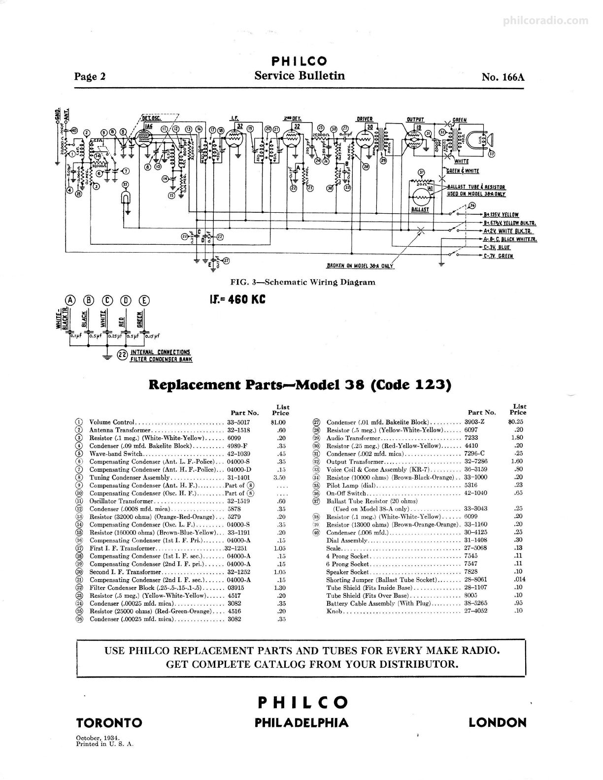
Service Bulletin No. 166-A
Models 38 and 38-A (Code 123)
The Philco Models 38 and 38-A are battery-operated
five-tube superheterodyne receivers. Model 38 is design ed
for use with a two-volt storage battery for filament ("A")
supply; Model 38-A for use with dry "A" batte ry,- in
conjunction with a Type lAl ballast tube. The frequency
range is 545 to 2415 kilocycl es, and a wave-band switch
permit s the selection of eithe r the standa rd broadcast or
police and amateur radio station s. Models 38 and 38-A
possess receiver chasses that are identical. When shipp ed,
Model 38 has a shorting jump er across the filament con-
tacts of the Type lAl Ballast Tube socket. This shou ld
not be disturbed as long as the receiver is operated upon
the storage batt ery. Removal of it will open the filament
circuit. The Model 38-A,-in add ition to its complement
of five tubes,-is equipped with a Type lAl ballast tube
which must be used with the receiver operating on dry
"A" battery. A special resistor is used across the filament
of the Type lAl ballast tube .
The Models 38 and 38-A employ a Philco Type 1A6
tube as det ector-oscillato r, a Type 32 tube for the inter-
mediate frequenc y amplifier, a Type 32 as second detector ,
a Type 30 tube for the first audio frequenc y stage, and a
Type 19 tube as output (class "B" amplifier ). The se are
the Philco low-current drain two-volt tubes.
The Model 38 is designed to be used with the Philco
Type 172-R two -volt sto rage battery and Philco Type
"P-9068" "B" /"C" battery; the Model 38-A with thr.
Philco Type "P-896" dry "A" battery and Philco Typ e
"P -9068" "B" /"C" battery.
Tube Socket Voltages
All Voltages Measure to Ground or -F
32
1A6 32 (I.F.) (2nd 30 19
Det.)
Plate .... 12i 12i .50 126 126
Screen G2 82
Grid . . . Gau 64 64 22 . .. . ....
Grid ..... G1 - 10 . .. . . . . .... G1 -2.9
G2 -2.9
FIG. 2-Bottom of Chassis Showing Parts;
and Sockets for Testin~ Voltages
The filament ("A") supply should never exceed two
volts at the tube socket termin als of either Model. The
Type lAl tube acts as a voltage-regulator, and maintains
a constant "A" potenti al to the filaments of the Model
38-.
.\.. The filament current drain upon the "A" batter y is
720 milliampere s. The "B" batt ery curre nt drain varies
between 8 and 12 milliampere s,-a t 135 volt s. The inter-
mediate frequency of the superheterodyne circuit is 460
kilocycle s.
FIG. I-Locations of Compensating Condensers
NOTE: Compensators ®and@) are shown as viewed from
top of chassis ; all others in position seen from bottom.
Adjusting Compensating Condensers
Adjustment , of compensating condensers in Model 38
requires the use of an accurate signal generator (such as
the Phil co Mode l 024), an output meter (Phil co Mode l 012
or 02:j are recommended ) and a special adjusting wrench
(Philco No. 3164). Th e I. F. or intermediate frequency
of the set is 460 IC C. Refer to Fig. 1 for locations of
compensating condensers.
.l. F.-Set signal generator at 460 K. C. Remove grid clip
from cap of 1A6 tube and connect antenna lead from
signal generator to cap of tube, connect ground lead
to ground post of set. Set dial of receiver at 550 and
wave hand s"·itch rit left . See that set is connected
to lmt.teries and volume contro l full "on ." Connect
output meter to primary terminals of output trans -
former (in chassis). Turn "on" the receiver and signal
generator. Adjust the four I. F. compen sat ing con-
densers @, @, @ and ® to give maximum
response in the output meter. The se adjustments are
all made from the rear of the chassis through holes
in sub-base .
.\ :'\T. II. F. and OSC. H. F. (standard wave )-The se are
condensers ® and @) located on top of the tuning
condenser assembly and adjusted from above. ® is
the one nearest the front of chass is. Ret signal gene-
rator at 1500. Replace grid clip on cap of lAG tube
and connect antenna and ground leads from signal
generator direct to antenna and ground posts of set.
Turn dial of set to 150 and adjust condensers ® and
@)for maximum reading in output meter.
OSC. L. F. (standard wave)- Set signal generator at 600
and turn dial of set to 60. Adjust condenser @,
reached from rear of chassis, to give maximum read-
ing in output meter.
A~T. H. F. and L. F. (police band )- Turn w:we band
switch to the right . Set signal generator at 2400 and
dial at 2.4 (lower scale). Adjust condenser (J) to
give maximum response in output meter. Now turn
dial to 1.5 and set signal generator at 1500. Adjust
condense r ® for maximum response. Condensers
® and (J) are reached through the two holes in top
of chassis to rear of tuning condenser assembly .
.:i°OTE: If readi ng on output meter is too great during ad-
jnstment~, turn down "attennato r" on signa l
µ:cnerator.
philcoradio.com
Page 2 PH I LCO
Service Bulletin No. 166A
.,~
"7rt-r-r-t--..._t-- t-- t- --- -6----+--+--..._--+-++=~~+4- --c"~ ..h'isv.lflil!.
r--t-t--1-------- -t-- -t-- __._---- -++- - -+++--+--- .-,,.+,,--~ ,mt~rmawe1K.n.
~---<>-------::--t.t-t- - 4-----t- --6----------+4- ---+4-4-~ ~ ...i.-...<f"o--{-----_M,gv,WHITEeurn,
k, t ~ BLACKWHITf.m.
~ -,~ ----1--....,., ~ -k,:!Y ,.!bl!I.
~--------------i--t -t :------- ---------4-- - - - /...,L----l- -<f"- ~ Ti.~
BROKENONMOOfL38·A ONLY
FIG . 3- Sch cm at ic Wirin g Diagr am
®®©®® II.=460 KC
~;tlil
o.,pf o.s~f o.,sµf o.s~f o.,s~f
@ fNTERIIALCONN£CTIONS
"'r FILTERCONDENSERBANK
Replacement Parts--Model 38 (Code 123)
Lis t List
Part No. Price Part No . Price
CD
Volume Contro l. . . ............. 33- 5017 $1.00 @ Condenser (.01 mid. Bakelite Block) ...... 3903-Z $0.25
® Antenna Transformer .... . 32-1 518 .60 @) Resisto r (.;j meg.) (Yellow-White-Ye llow)... 6097 .20
® Resisto r (.1 meg.) (White-Wh ite-Yellow) .. . . . . 6099 .20 @) Audio Transformer . . . .. 7233 1.80
© Condenser (.09 mid. Bakelite Block) . .. . .... . . 4989-F .3.5 @ Resistor (.25 mcg.) (Red-Ye llow-Yellow) .... 4410 .20
® Wave-ban d Switch. 42-1039 .45 ® Condenser (.002 mid. mica) . 7296-C -25
® Compensating Condenser (Ant. L. F.-Police) .. 04000-S .
3,, @ Output Transformer ...... 32-7286 1.60
(]) Compensating Condense r (Ant. H. F .-Police) .. . 04000-D .L"i @J Voice Coil & Cone Assembly (KR-7). 36-3159 .80
® Tuning Condense r Assembly . .. 31-1401 3..oo @ Resistor (10000 ohms) (Brown-Black-Orange). 33-1000 .20
® Compensating Condenser (Ant. H.F .)..... .... Partol ® @ Pilot Lamp (dial) . . .. 5316 .23
@ Compensating Condenser (Osc. H. F.). .Part of ® @ On-Of! Switch. 42-1040 .65
@ Oscillator Transformer .. 32-1519 .60 ® Ballast Tube Resistor (20 ohms)
@ Condenser (.0008 mid. mica). 5878 .3,5 (Used on Model 38-A only) .. 33-3043 .25
@ Resistor (32000 ohms) (Orange-Red-Ora nge). .. 5279 .20 @) Resistor (.1 meg.) (White-White-Yellow). 6099 .20
@ Compensat ing Condenser (Osc. L. F.). . ... 04000-S .3,i ,':{9 Resistor (13000 ohms) (Brown-Orange-Orange). 33-1160 .20
@ Resistor (100000 ohms) (Brown-Blue-Yellow).. . 33-1191 .20 @ Condenser (.006 mid.). 3Q-4125 .25
@ Compensating Condenser (1st I. F. Pr i.).... 04000-A .15 Dial Assembly . 31-1408 .30
@ First I . F. Transformer. . . .32-1251 1.05 Scale... 27- 5068 .13
@ Compensating Condenser (1st I. F. sec.) ..... . . 04000-A .15 4 Prong Soc1;.et. . .. . . ... . . .. . 7545 .11
@ Compensat ing Condenser (2nd I. F . pri.) .... . . 04000-A .1.5 6 Prong Socket. 7547 .11
@) Second I. F. Transformer ...... . ...... . 32- 1252 1.05 Speaker Socket . 7828 .10
® Compensati ng Condenser (2nd I. F. sec.) . . . . .. 04000 -A .15 Shorti ng Jumper (Ballast Tube Socket) . . . 28-8061 .014
@ Filter Condense r Block (.25-.5-.15-.1-.5) .. . .. . . 03915 1.30 Tube Shield (Fits Inside Base). 28-1107 .10
@ Resistor (.5 meg.) (Yellow-White-Yellow) .. . . .. 4517 .20 Tube Shie ld (Fits Over Base ) . 8005 .10
@ Condenser (.00025 mid. mica) .. 3082 .35 Batter,v Cable Assembly (With Plug). 38-526,5 .95
@ Resistor (25000 ohms) (Red-Green-Orange) . ... 4516 .20 Knob . .. . .................... 27-4052 .10
@ Condenser (.00025 mfd. mica) ..... ······· ··· · 3082 .3.5
USE PHILCO REPLACEMENT PARTS AND TUBES FOR EVERY MAKE RADIO.
TORONTO
October, 1934.
Printed in U. S. A.
GET COMPLETE CATALOG FROM YOUR DISTRIBUTOR.
PHILCO
PHILADELPHIA LONDON
philcoradio.com

This manual suits for next models

1

Other Philco Receiver manuals

Philco 38-14 Reference manual

Philco

Philco 38-14 Reference manual

Philco 50 User manual

Philco

Philco 50 User manual

Philco 37-61 Reference manual

Philco

Philco 37-61 Reference manual

Philco 76 User manual

Philco

Philco 76 User manual

Philco 41 User manual

Philco

Philco 41 User manual

Philco 95 User manual

Philco

Philco 95 User manual

Philco 38-116 Reference manual

Philco

Philco 38-116 Reference manual

Philco 39-85 Reference manual

Philco

Philco 39-85 Reference manual

Philco 39-25 Reference manual

Philco

Philco 39-25 Reference manual

Philco 121 Reference manual

Philco

Philco 121 Reference manual

Philco 34 User manual

Philco

Philco 34 User manual

Philco 30 User manual

Philco

Philco 30 User manual

Philco 45 User manual

Philco

Philco 45 User manual

Popular Receiver manuals by other brands

Zoom 4360 quick start guide

Zoom

Zoom 4360 quick start guide

Pioneer VSX-LX52 operating instructions

Pioneer

Pioneer VSX-LX52 operating instructions

MAASLAND R500M manual

MAASLAND

MAASLAND R500M manual

JVC KS-RT313 instructions

JVC

JVC KS-RT313 instructions

GAI-Tronics XCP0030A installation instructions

GAI-Tronics

GAI-Tronics XCP0030A installation instructions

Pioneer MVH-X189UI owner's manual

Pioneer

Pioneer MVH-X189UI owner's manual

Leica GM30 user manual

Leica

Leica GM30 user manual

Altronix eBridge PLUS eBridge8PCRM installation guide

Altronix

Altronix eBridge PLUS eBridge8PCRM installation guide

Grundig M 100-CF Service manual

Grundig

Grundig M 100-CF Service manual

Carrier XCT 7 manual

Carrier

Carrier XCT 7 manual

FrSky D6FR instruction manual

FrSky

FrSky D6FR instruction manual

BFT CLONIX 2E AC U-LINK 230 installation manual

BFT

BFT CLONIX 2E AC U-LINK 230 installation manual

HEINE DELTA 20 quick start guide

HEINE

HEINE DELTA 20 quick start guide

Offshore 3185 user manual

Offshore

Offshore 3185 user manual

Sennheiser HDE 2020-D-II - quick guide

Sennheiser

Sennheiser HDE 2020-D-II - quick guide

GoRave RE1 owner's manual

GoRave

GoRave RE1 owner's manual

Shinybow USA SB-6230R instruction manual

Shinybow USA

Shinybow USA SB-6230R instruction manual

Wisenet SBP-317HM quick start guide

Wisenet

Wisenet SBP-317HM quick start guide

manuals.online logo
manuals.online logoBrands
  • About & Mission
  • Contact us
  • Privacy Policy
  • Terms and Conditions

Copyright 2025 Manuals.Online. All Rights Reserved.