manuals.online logo
Brands
  1. Home
  2. •
  3. Brands
  4. •
  5. Philco
  6. •
  7. Receiver
  8. •
  9. Philco 39-85 Reference manual

Philco 39-85 Reference manual

• • • • • • •
SERVICE BULLETIN NO. 307 for members of
RADIO MANUFACTURERS SERVICE
A PHIi.CO Service Plan
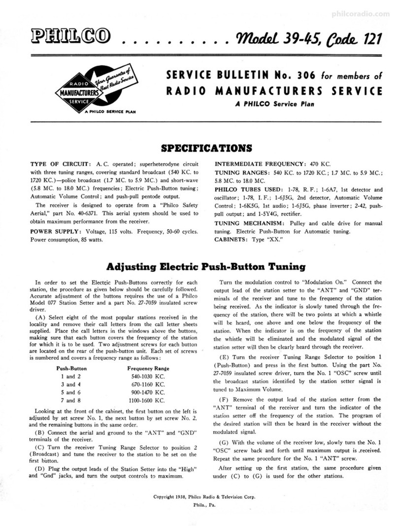
Adjusting Push-Button Tuning to Stations
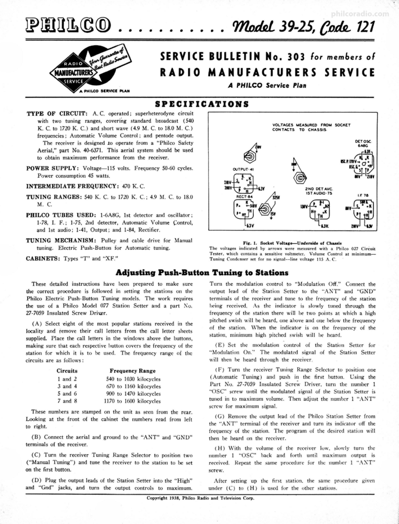
In order to set tile Eiectric push-buttons correctly for each station,
the procedure as given below should be carefully followed. Accurate
adjustment of the buttons requires the use of a Philco Model 077
Station Setter and a Part No. 27-7059 insulated screw driver.
(a) Select six of the most popular stations received in the
locality and remove their call letters from the call letter sheets
supplied. Place the call letters in the windows above the buttons,
making sure that each button covers the frequency of the station for
which it is to be used.
Two adjustment screws for each button are located on the rear
of the push-button unit. The top row of screws are for the antenna
circuit and the bottom row of screws for the oscillator circuit.
Thes e are marked "Ant" and "Osc. " Each set of screws is num-
bered and covers a frequency range as follows :
Push Button Frequency Range
1. . . . . ... ... . ..... . ... 970 to 1550 KC
2............. . ....... 970 to 1550 KC
3. . . . . . . . . . . . . . .. . . . . . 750 to 1250 KC
4. . . . ............ . ... . 750 to 1250 KC
5...... . ...... . ..... . . 970 to 1550 KC
6................. . . . 970 to 1550 KC
Looking at the front of the cabinet, the first button on the left
is adjusted by set screws l\'o. 6, the next button by set screws No. S,
and the remaining buttons in the same order.
(8) Connect the Philco Farm Radio aerial , Part No. 40-6383,
and ground to the "ANT " and "GND " terminals of the receiver .
(C) Turn the receiver Tuning Range Selector to position two
(Manual Tuning) and tune the receiver to the station to be set on
the first button.
(D) Plug the output leads of the Station Setter into the "High"
and "Gnd" jacks , and turn the output controls to maximum. Turn
the modulation control to "Modulation On." Connect the output
lead of the Station Setter to the "ANT" and "GND" terminals of
the receiver and turn the indicator to the frequency of the station
being received. As the indicator is slowly tuned through the fre-
quency of the station there will be two points at which a high
pitched whistle will be heard, one above and one below the frequency
of the station . When the indicator is on the frequency of the station,
the whistle will be eliminated and the modulated signal of the
Station Setter will then be clearly heard through the receiver .
(E) Turn the receiver Tuning Range Selector to position one
(Push-button) and push in the first button. Using the Part No.
27-7059 Insulated Screw Driver, turn the number 6 "OSC" screw
until the . modulated signal of the Station Setter is tuned in to
maximum volume. Then adjust the number 6 "ANT" screw for
maximum volume.
(F) Remove the output lead of the Philco Station Setter from
the "ANT" terminal of the receiver and turn its indicator off the
frequency of the station. The program of the desired station will
then be heard on the receiver.
(G) With the volume of the receiver low, slowly turn the num-
ber 6 "OSC" screw back and forth until maximum output is
received. Repeat the same procedure for the number 6 "ANT"
screw.
After setting up the first station, the same procedure given under
(C) to (G) is used for the remaining buttons.
Alignment of Compensators
EQUIPMENT REQUIRED:
( 1) Philco Model 077 Signal Generator which has a fundamental
frequency range from 115 to 36,000 KC is the correct instrument
for this purpose.
(2) Output Meter, Philco Model 027 Circuit Tester, incor-
porates a sensitive output meter and is recommended.
Opera - Signal Generator .Kece1ver
ti1,ns Output Dummy Dial Dial Control
in Connecti ons Antenn a Setting Setting Settings
Order to Receiver (Note A)
1 1A7G Grid .1 mf 470 KC 580KC Vol. Cont.
max.
- - -
2 Ant. Lead 400ohms 18.0MC 18.0MC Vol. Cont.
(white) max.
--- 3 Ant. Lead 225 mmf 1550KC 1550KC Vol. Cont.
(white) max .
4 Ant. Lead 225 mmf 580KC 580KC Vol. Cont.
(white) max .
-- -
5 Ant. Lead 225 mmf 1550KC 1550KC Vol. Cont.
(white) max.
NOTE A- The "Dummy Antenna " consists of a condenser or resistor con-
nected in series with the signal gmerat or output lead (high side). Use the
capacity or resistance as specified in each step of the above procedure .
(3) Philco Fiber Handle Screw Drive r, part No. 27-7059 and
Fiber Wrench, part No. 3164.
OUTPUT METER: The Philco 027 Output Meter is connected
to the plate and screen terminals of the 1A5G tube. Set the meter
to use the 0-30 volt scale.
Adju st Specia l
Compensators Instruc-
in Order tions
(20A)
(19B) (19A)
(6B) See Note
B
(9) (6A)
(9A) Roll gang
(9) Fig. 1. Locations of Compensat ors
NOTE B-DIAL CALIBRATION : In orde& to adjust the receiver correctly,
the dial must be aligned to track properly with. the tuning condenser, To
adjust the dial proceed as follows : _Turn the tunmg condense,: to ~ax1mum
capacity (plates fully meshed) . W 1th tunmg condenser m this pos1t10n set
the pointer horizontally across the dial.
Copyright 1938, Philco Radio & Television Corp.
Ph ila ., Pa.
philcoradio.com
Specifications
TYPE OF CIRCUIT: Four tube, battery operated superhetrod yne cir-
cuit, two tuning ranges, Automatic Volume Control, and Pentode
Output.
TUNING RANGES: Range I, 540 to 1720 KC.; Range 2, 5.6 to
18.0 MC.
INTERMEDIATE FREQUENCY: 470 KC.
PHILCO TUBES USED: I-IA7G, 1st Detector and Oscillator ;
l-IN5G, I. F. Amplifier; l-1H5G, 2nd Detector, 1st Audio, and
Automatic Volume Control; and l-1A5G , Output.
AERIAL AND GROUND: Philco "Farm Radio Aerial," part No.
40-6383, is required for maximum performance . A good ground is
very essentia l.
CABINETS: Typ es "B" and "XF."
BATTERIES REQUIRED: One Philco "A" Pack, part ?\o. 41-8014,
and one Philco "B" Pack , part No. 41-8015.
BATTERY DRAIN: 6.5 Ma. "B" and 200 Ma. "A." Total with
no signal.
TUNING MECHANISM: Pu lley and cable drive for Manual tuning.
Electric Push-Button for Automatic Tuning.
ANT. lo
!'H
~~';'©~'t:l:'r
1\el[~s/IT~i
~TIii._ tlNO(IISll
@
1.f.=470 KC.
'"""::z:...~-
rlll Ot.lll{ Alt or !W I TCH .
)······--·~•-·
4Yt
II .SUPPLY
1.1)'t'OLTS 90 'fOlTS
~OWN U:O~ltl
fe>
.,.,.
Replacement Parts
Model 39-85, Code 121 Fig. 2. Schematic Diagram
Schem.
No. Description
1 Antenna Tran sformer , Range 2
Part
No.
(lncls. No. 3) .... . ...... . .. 32-3092
2 Ant enna Transformer, Range I 32-3084
3 Condenser (19 mmf) (part of
No. l) ........ . ........... 30-1090
4 Condenser (.05 mf tubular) ...
5 Resistor (2.0 megohms, ½ watt)
6 Tuning Condenser Assembly ... .
7 Oscillator Transf orm er, Rang e I
8 Oscillator Tran sformer , Ran ge 2
9 Compensator (two sections) .....
10 Resistor (70 ,000 ohms, ½ watt).
11 Condenser (.05 mf tubular) ... .
12 Condenser (4500 mmf mica) .. .
13 Resistor (190 ,000 ohms, ½ watt)
14 Condenser (500 mmf mica) .. .. .
15 Resistor (5000 ohms , ½ watt).
16 Electrolytic Conden ser (6 mf -
3 mf) .. ...... . .... . .... .
17 Resi stor (5000 ohms, ½ watt) .. .
18 Resi stor (2.0 megohms) .. ..... .
19 !st I. F. Tran sform er Assemb ly.
20 2nd I. F. Transf ormer Assembly
21 Resistor (51,000 ohms, ½ watt)
22 Resistor (490 ,000 ohms , ½ watt)
23 Condenser (.01 mf tubul ar) .... .
24 Condenser (150 mmf mica) . . .. .
25 Resistor (99 ,000 ohms, ½ watt)
26 Condenser (.003 mf tubular).
27 Volume Control and On -Off
Switch .. ....... . ......... .
30-4519
33-520339
31-2300
32-3082
32-3085
31-6100
33-370339
30-4444
30-1109
33-419339
30-1114
33-250330
30-2348
33-250 339
33-520339
32-2841
32-.1081
.13-351339
33-449339
30-4572
30-1033
33-3993.JO
30-4580
33-5288
Sch em. Part
No. Description No .
28
29 Re sistor (800 ohm s, ]/, watt) .. 33- 180339
Resistor (2.0 megohms, ½ watt) 33-520339
30 Resistor (1.0 megoh m, ½ watt) 33,510339
31 Condenser (.01 mf tubular) .... 30-45 72
32 Condenser (.0005 mf mica) .... 30-1114
33
34 Output Tr ansfo rmer .... ...... 32-7984
Cone & Voice Coil Assemb ly for
Speaker (Part No. 36- 1410) .. 36-4093
Cone & Voice Ceil Assembly for
Speaker (Part No. 36-1436) .. 36-4094
35 Condenser (250 mmf , silver
plated mica) ............... 30-1104
36 Conden ser (420 mmf, silver
plated mica) ........... 30-1116
37 Osci llat or Coil Assem. (High
freq. No. l and 2) ... ........ 32-29 41
38 Oscillator Coil Assem . (Medium
fr eque ncy No. 3 and 4) _. . . . . 32-2942
39 Oscillator Coi l Assem. (Low fre-
quency No. 5 and 6) . 32-2943
40 Compensator (two sections)
(Nos. I and 2) . .......... .. 31-6244
41 Compensator (two section s)
(Nos. 3 and 4) .......... ... 31-6245
42 Compensator (two sections)
43
44
(Nos. 5 an d 6) ............. 31-6246
Push -Button Switch .. . . , .....
Wave Switch ..... •. ..
Bez el Assy. (Dial) ... . _.. .. . .
Cable (Battery) .... _........ .
Dial Assy ... . ............ . . ..
Dial Pointer ..... . . . ........ .
Dia l Drive Cord . . . ... . . _. . . . .
42-1471
42-1466
40-6374
41-3437
31-2307
56-1091
31-2318
Fig. 4. Automatic Tuning Unit
Description
Dial Drive Spring ·.. .... ... .. . .
Dial Tuning Shaft .... .. . . . .. .
Escutcheon (Push-Button) .... .
Knob (Push-Button) .. ....... .
Knob (Range Switch) . . ...... .
Knob (Volume & Tuning) . . .. .
Pulley (Tuning Condenser) ... .
Speaker (B Cabinet) .... ... .. .
Speaker (XF Cabinet) ........ .
Socket (6 prong) ..... .. .. .. . .
Socket (7 prong) ..... ... .... . .
Socket (Speaker) .. ..... ..... .
Tab Kit ................. . .. .
Part
No.
28-8 751
31-2290
28-5561
27-4702
27-4321
27-4332
28-6662
36-1410
36-1436
27-6086
27-6099
27-6115
40-6408
Fig. 3. Part locations, underside of chassis
PHILCO RADIO
AND TELEVISION CORPORATION
\
Parts and Service Division
Philadelphia, Pa.
August 1938 Printed in U. S. A.
philcoradio.com

Other Philco Receiver manuals

Philco 38-14 Reference manual

Philco

Philco 38-14 Reference manual

Philco 76 User manual

Philco

Philco 76 User manual

Philco 39-25 Reference manual

Philco

Philco 39-25 Reference manual

Philco 95 User manual

Philco

Philco 95 User manual

Philco 38-116 Reference manual

Philco

Philco 38-116 Reference manual

Philco 41 User manual

Philco

Philco 41 User manual

Philco 30 User manual

Philco

Philco 30 User manual

Philco 38 User manual

Philco

Philco 38 User manual

Philco 34 User manual

Philco

Philco 34 User manual

Philco 50 User manual

Philco

Philco 50 User manual

Philco 121 Reference manual

Philco

Philco 121 Reference manual

Philco 45 User manual

Philco

Philco 45 User manual

Philco 37-61 Reference manual

Philco

Philco 37-61 Reference manual

Popular Receiver manuals by other brands

brel-motors DD1680 installation manual

brel-motors

brel-motors DD1680 installation manual

RSF Elektronik AK MS 45 Mounting instructions

RSF Elektronik

RSF Elektronik AK MS 45 Mounting instructions

Sonoro Maestro SO-1010 operating manual

Sonoro

Sonoro Maestro SO-1010 operating manual

Keysight x series Getting started guide

Keysight

Keysight x series Getting started guide

Amphony 1500 Technical specifications

Amphony

Amphony 1500 Technical specifications

Beamz BBP W-DMX instruction manual

Beamz

Beamz BBP W-DMX instruction manual

Global Test Supply TW-82P quick start guide

Global Test Supply

Global Test Supply TW-82P quick start guide

Harman Kardon AVR 147 owner's manual

Harman Kardon

Harman Kardon AVR 147 owner's manual

Alcor HD-2000 user manual

Alcor

Alcor HD-2000 user manual

Maxilux H3-RCV-4CV instructions

Maxilux

Maxilux H3-RCV-4CV instructions

Harman Kardon AVR 147 Service manual

Harman Kardon

Harman Kardon AVR 147 Service manual

Fracarro HOME FIBRE OPT-RX 4 MICRO operating instructions

Fracarro

Fracarro HOME FIBRE OPT-RX 4 MICRO operating instructions

in digital DVB-C8080CO Operation manual

in digital

in digital DVB-C8080CO Operation manual

Listen LR-400-150 Quick reference card

Listen

Listen LR-400-150 Quick reference card

Sharp MD-R3H Service manual

Sharp

Sharp MD-R3H Service manual

GRAUPNER GR-12L SUMD+T manual

GRAUPNER

GRAUPNER GR-12L SUMD+T manual

Topmodel XPower R4-B user manual

Topmodel

Topmodel XPower R4-B user manual

Sony DIRECTV RECEIVER SAT-W60 installation guide

Sony

Sony DIRECTV RECEIVER SAT-W60 installation guide

manuals.online logo
manuals.online logoBrands
  • About & Mission
  • Contact us
  • Privacy Policy
  • Terms and Conditions

Copyright 2025 Manuals.Online. All Rights Reserved.