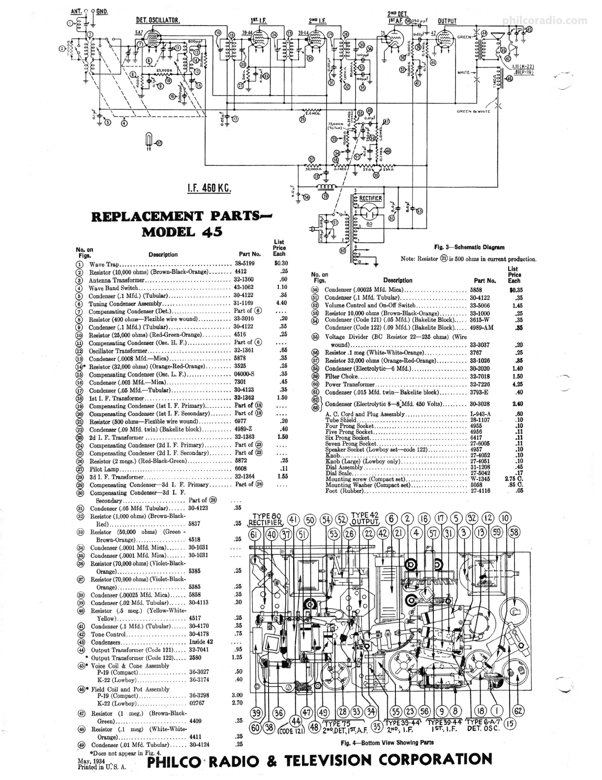
manuals.online logo
Brands
  1. Home
  2. •
  3. Brands
  4. •
  5. Philco
  6. •
  7. Receiver
  8. •
  9. Philco 45 User manual

Philco 45 User manual

-
PHILCO
Q0.1/.a.PAT. or,
Service Bulletin~ No. 191
Model 45
Philco Model 45 is a six tube receiver operating on alternating current and capable of receiving
either standard and police broadcasts between 540 and 1720 kilocycles, or short-wave stationS:~between
4.2 and 13 megacycles . The left hand side of the dial is calibrated in kilocycles for standard reception
and the right in megacycles for short-wave stations. A two-position switch changes reception from
standard to short -waves.
Mod~l 45 uses a type 6-A-7 detector-oscillator, two type 39-44 I. F. Tubes, type 75 2d detector,
type 42 output tube, and type 80 rectifier. The power consumption is 65 watts. The intermediate
frequency is 460 K.C.
Tube Socket Voltages
Det. 1st 2d 2d Out-
CIRCUIT Osc. IF IF Del. put Rect.
-- -- -- -- --
TypeTube 6A7 39-44 39-44 75 42 80
- - -- -- -- - -
Filament (F to F) ... 6.3 6.3 6.3 6.3 6.3 5.0
- - -- -- -- --
Plate (P to K).... 260 255 255 175 250 335
-- -- -- -- --
Gl-35
Screen Grid (SG to K/... . . 02-135 75 75 ... 260
03&5-85 -- - - -- - - --
Cathode (K to F).... 4.2 3.8 3.8 0 0 ...
The above te.,ts were made with an AC voltmeter for filament voltages and a
high resistance DC voltmeter-for all others. Dial at 550 KC, volume control at
maximum. Test made with test prods applied to socket terminals underneath
chassis. Line voltage 115.
.8.D
RECTIFIER
~
~
ill
DET.DSC.
Gs&.G1
--
'
~
S<
Pe •
-- .,. 39-44
1
11 IF.
Fig. 1-Tube Socket Layout (underside)
Power Transformer Voltages
Terminals Volts Circuit
1-2 120 Primary
3-4 5.0 Fil. of 80
5-7 680 Plates of 80
8- 10 6.3 Filaments
6 Center of 5-7
9 Center of 8- 10
fREOUEJ4CY·IWID TONE
$WITCH CONTROL
Flg.·2-Chasals Top View
Color Leads
White
Blue
Yellow
Black
Yellow-Gr een tr.
Black-Yellow tr.
---42 80
;,,- ~:=;::::;l-75
Adjusting Compensating Condensers
For adjustment of compensating (padding) condensers in
model 45, an accurately calibrated signal generator and a
special insulated padding wrench are needed. We suggest the
Philco Model 024 Signal Generator or the 048 Tester which
includes a similar instrument.
The chassis must be removed from cabinet in order to make
all adjustments .
Adjustments are made in the following order-
ADJUSTMENT OF THE INTERMEDIATE FRE-
QUENCY-Remove the grid clip from the type 6A7 tube
and connect the "ANT" output terminal of the signal gen-
erator to the grid cap of the tube. Connect the "GND"
terminal of the signal generator to the "GND" terminal of
the receiver chassis.
Connect the output meter to the primary terminals of the
outpu t transformer. Set the signal generator at 460 K.C. (the
intermediate frequency of Model 45) and with the receiver
and signal generator turned on, the wave band switch at left
and dial at 600 K.C., adjust each of the I. F. compensating
condensers in turn, to give maximum response in the output
of the receiver. The three pairs of I. F. compensating con-
densers are located one pair at the top of each of the three I. F.
transformer shields. These are the three metal "cans" near
the rear of the chassis. Each of the transformers has a dual
compensating condenser mounted at its top, and accessible
thru a hole in the top of the coil shield. In the dual compensa-
tors, the Primary circuit is adjusted by turning the screw; the
Secondary circuit is adjusted by turning the hex-head nut.
ADJUSTMENT OF THE WAVE TRAP-Replace the
grid clip upon the Detector-Oscillator tube (Type 6A7).
Connect the output leads from the signal generator directly
to the antenna and ground terminals of the receiver. Set the
Wave-Band Switch of the receiver to the standard broadcast
band (left hand position) and the Station Selector at the lQ;w
frequency (540 K.C .) end. Adjust the Wave Trap condenser
to give MINIMUM response to a 460 K.C. signal from the
signal generator. The Wave Trap CDis located at rear and
underneath the chassis, and is shown in Figure 4. It is
reached from the rear of the chassis, by inserting the fibre
wrench thru the hole near right-hand rear corner of chassis.
DETECTOR, AND OSCILLATOR "HIGH" '1\.ND "LOW"
FREQUENCY ADJUSTME~TS-The "ante nna" and
"oscillator H. F." compensators are located on top of the
tuning condenser assembly, reached from above.
Set the signal generator at 1500 K.C., tune in this signal on
the set and adjust the antenna compensator G) (nearest tuning
control) to give maximum reading in the output meter.
Next adjust the oscillator H. F. condenser @ (located on
the other section of tuning condenser) to maximum reading .
l<'inallyset the signal generator at 600, tune in t.his signal
and_adjust the oscills.'tor "L. F. condenser", located under-
neat}!. chassis (@ in Fig. 4) to maximum reading . This
adjustment is reached thru ,the hole in top of chassis, between
the two electrolytic condensers (left hand end of chassis when
facing rear). '
philcoradio.com
l.f.460KC.
REPLACEMENT PARTS,,_
MODEL 45
No.on
/S(
C R( C"I &\o/'HIT C
Fig. 3-Schematlc Diagram
Figs. Description Pan No.
~
::to~~fo,ooo
~~)
(B~~;.:~-B~k:~~i::::::::!~
109
List
Price
Each
$0.30 Note: Resistor® is 500ohmsin current production.
@ AntennaTransformer... ........ .. .. . .... . .. ....... 32--1360
© WaveBand Switch.... ............. .. ... ... 42--1062
@ Condcneer(.1Mfd.) (Tubular)....... .. ..... 30-4122
@ Tuning CondeneerAssembly..... . . . . .. . . .. 31-1169
G) CompensatingCondenser(Det.). . .. ... . . . ... . . .. . .. . Part of ©
@ Resistor(400 ohms-Flexib le wirewound)...... .. .. .. 33-3016
@ Condenser(.1 Mfd.) (Tubular).. ........ . .. . .. ... .. . 30-4122
IResistor(25,000ohms)(Red-Green-Orange).. . . .. ... . 4516
CompensatingCondewier(Osc.H. F.)....... ... ... ... Part of@
OscillatorTransformer... ...... .. ,. . . . .... . .. . .. .. . 32-1361
ICondenser(.0008Mfd.-Mica) ... .... .. .. . .... .. .... 5878
• Resistor(32,000ohms)(Orange-Red-Orange). . . ... ... 3525
Compensating
Condenser(Oec.L. F.).. ........ . .. .. . 04000-S
@ Condenser(.003Mfd-Mica) .... ... ...... .. . .. .. .. . 7301
Condenaer(.05Mfd.-Tubular) ......... . . ..... . . .. . 30-4123
1st I. F. Transformer...... . . .. . . ........... . ...... 32--1362
CompensatingCondenser
(1st I. F. Primary).. .... . .. . Part of@
Compensating
Condenser(1st I. F. Seoondary)....... . Part of@
Resistor(500
ohms-Flexible wirewound)...... . . . .. . 6977
CondeDBer
(.09Mfd. twin) (Bakelite block).... .. . .. . 4989-Z
2d I. F. Transformer... . . ...... . . . ..... . . .. . . ..... 32--1363
Compensating
Condenser(2d I. F. Primary)..... . . Part of@
Compensating
Condenser(2d I. F. Secondary). . . Part of @
Resistor (2 mega.)(Red-Black-Green).. . . . ..... . .. .. 5872
Pilot Lamp.. .. .. ..... .. .... . .. . .. .. .. .. . .. .. .. .. . . 6608
3d I. F. Transformer... . . ....... . . .. . . ... 32--1364
Compensating Condenscr---3d
I. F. Primary. . . . . . . . Part of @
Compensating Condenser-3d I. F.
Secondary... .. .. .. .. .. .. .. .. .. . Part of @
@ Condenser(.05 Mfd. Tubular)... . .. 30-4123
@) Resistor(1,000ohms)(Brown-Black-
Rcd).... .... .. . .. ' ... 5837
@ Resistor (50,000 ohms) (Green -
Brown-Orange)... .... . . . .... . .. 4518
@ Condenser(.0001Mfd.Mica)..... . 30-1031
@ Condenser(.0001Mfd. Mica)... .. .. 30-1031
® Resistor(70,000ohms)(Violet-Black-
Orange).. ... . .. .. .. . .. ... .. . 5385
® Resistor(70,000ohms)(Violet-Black-
Orange)...... .. .. .. .. .. .. .. 5385
@ Condenser(.00025Mfd. Mica)... ... 5858
@ CondcD!ler(.02 Mfd. Tubular).. . . .. 30-4113
@) Resistor (.5 meg.) (Yellow-White-
@
@
Yellow)...... .. .. 4517
Condenser (.I Mfd.) (Tubular).... .. 30-4170
Tone Control... . . . 30-4178
@ Condensers.. ... Inside42
@ Output Transformer(Code121)..... 32-7041
• Output Transformer (Code122)..... 2580
@• Voice Coil & Cone ABBembly
P-10(Compact) .... . .
K-22(Lowboy).
@* Field Coil and Pot Assembly
P-10(Compact.)... .
K-22(Lowboy).. ..
.. 30-3027
30-3174
30-3298
.. 02767
@ Resistor (1 meg.) (Brown-Black-
.36
.25
.25
.25
.25
.35
.30
.25
.35
.75
.95
1.25
.50
.40
3.00
2.70
Green).. .. .. . 4409 .25
@ Resistor (.1 meg) (White-White-
.25
.60
1.10
.35
4.40
.20
.35
.25
.65
.35
.25
.35
.45
.35
1.50
.20
.40
1.50
.25
.11
1.55
No. on
Figs. Description Pan No.
@) Condenser(.00025Mfd. Mica).... . . . . . . .. . ... 5858
® Condeneer(.1 Mfd. Tubular). ......... ........ .. ... 30-4122
@) VolumeControl and On-OffSwitch.. .. . . .. . . .. .... .. 33-5066
@ Resistor 10,000ohms(Brown-Black-Orange)... .... . .. 33-1000
@ Condenser(Code 121)(.05 Mfd.) (Bakelite Block)... . . 3615-W
Condenser(Code122)(.09Mfd.) (BakeliteBlock)... .. 4989-AM
@ Voltage Divider (BC Resistor 22-2 35 ohms) (Wire
wound).... .. ... .. . . .. . .. . .. .. . .. .. . . .. . .. . . . .. . 33-3037
@) Resistor.1 meg(White-White-Orange).... ...... .. . .. 3767
@) Resistor32,000ohms(Orange-Red-Orange).... .. . .. .. 33-1026
ICondODBer(Eleetrolytic-jj Mfd.). ......... .... . .. . .. 30-2020
FilterChoke.... .. . .. . .. . ... . .... . .... .. ... ... ... . 32--7018
PowerTransformer.. .. . . .. . . .. . . .. . .. . .. .. .. . .. . .. 32--7226
~
Condenaer(.015Mfd.twin- ·Bakeliteblock).. . ... . .. . 3793-E
@}Condenser(Electrolytic8-(Mfd. 450 Volts)..... . .. . 30-3028
A. C. Cordand Plug Assembly.... .. . . . .. . .. .. .... .. lr943-A
Tube Shield.... .. .. .................. ..... . ...... . 28-1107
Four Prong Socket.... ..... . .. .. . ...... .. . . . ..... . . 4955
Five ProngSocket.. ..... . . . ..... . ..... . .. .. .... ... 4956
SixProng Socket.... . . . .. . .. . . . .. . . ... .. . . .. . .. . .. 6417
SevenProng Socket.. .. .. .. . . . .. ... .. .. . .. . . .. ... .. 27-6005
~~r-~~ket (1'.'~boy_set~~ _1_22_)_..·:: :: ::::: :: : i~~
052
Knob (Large)(Lowboyonly).......... ... .... .. .... 27-4051
Dial Assembly........ .. . .. . 31-1208
Dial Scale.. . .. .. . .. .. .. .. .. ... .. .. .. .. . .. .. .. .. . 27-5042
Mountingscrew(Compactset)... ... .. . . .. .. ... . .. W-1345
MountingWasher(Compactset).... . . . .. 5058
Foot (Rubber).... ......... . ............. .. ....... 27-4116
Orange)...... . .. .. .. .. .. .. .. .. . 4411 .25
@ Condenser(.01 Mfd. Tubular). ..... 30-4124 .25 Fig.4-Bottom ViewShowingPll'l8
it:19
~:~~-•:~inFPHIL(O ' RADIO & TELEVISION CORPORATION
-·,
List
Price
Each
$0,35
,35
1.45
.25
.35
.311
.20
.25
Jl6
1.40
1.50
4.211
.40
2.40
.60
.10
.10
.11
.11
.11
.10
.10
.10
.45
.17
2.75C.
.85C.
.06
.,-
.._
philcoradio.com

Other Philco Receiver manuals

Philco 38-14 Reference manual

Philco

Philco 38-14 Reference manual

Philco 50 User manual

Philco

Philco 50 User manual

Philco 39-85 Reference manual

Philco

Philco 39-85 Reference manual

Philco 38 User manual

Philco

Philco 38 User manual

Philco 34 User manual

Philco

Philco 34 User manual

Philco 41 User manual

Philco

Philco 41 User manual

Philco 39-25 Reference manual

Philco

Philco 39-25 Reference manual

Philco 38-116 Reference manual

Philco

Philco 38-116 Reference manual

Philco 121 Reference manual

Philco

Philco 121 Reference manual

Philco 30 User manual

Philco

Philco 30 User manual

Philco 95 User manual

Philco

Philco 95 User manual

Philco 37-61 Reference manual

Philco

Philco 37-61 Reference manual

Philco 76 User manual

Philco

Philco 76 User manual

Popular Receiver manuals by other brands

Sony STR-DG800 operating instructions

Sony

Sony STR-DG800 operating instructions

Elgato EyeTV Sat Free quick start guide

Elgato

Elgato EyeTV Sat Free quick start guide

Erone CDVI ERMU Use and installation  manual

Erone

Erone CDVI ERMU Use and installation manual

Kenwood KRF-9992D user guide

Kenwood

Kenwood KRF-9992D user guide

SHENZHEN FLYING INDUSTRY DEVELOPMENT CO.,LTD S1UA-DC06-ANT3 user manual

SHENZHEN FLYING INDUSTRY DEVELOPMENT CO.,LTD

SHENZHEN FLYING INDUSTRY DEVELOPMENT CO.,LTD S1UA-DC06-ANT3 user manual

BEA EAS RF user guide

BEA

BEA EAS RF user guide

Meyin RC-821 user manual

Meyin

Meyin RC-821 user manual

Sangean H203D manual

Sangean

Sangean H203D manual

Amphenol Procom PRO-DAR4 user manual

Amphenol Procom

Amphenol Procom PRO-DAR4 user manual

Yamaha CRX-N560 owner's manual

Yamaha

Yamaha CRX-N560 owner's manual

Dual XDM17BT user manual

Dual

Dual XDM17BT user manual

Pioneer VSX-1131 Basic Manual

Pioneer

Pioneer VSX-1131 Basic Manual

Triax TR 305 user manual

Triax

Triax TR 305 user manual

Sony SAT-A1 - Digital Satellite System operating instructions

Sony

Sony SAT-A1 - Digital Satellite System operating instructions

Ross HD DVB-S2 1201 user manual

Ross

Ross HD DVB-S2 1201 user manual

Audio Technica ATW-T3201 user manual

Audio Technica

Audio Technica ATW-T3201 user manual

Integra DTR-8.4 Service manual

Integra

Integra DTR-8.4 Service manual

Pioneer SX-315 Service manual

Pioneer

Pioneer SX-315 Service manual

manuals.online logo
manuals.online logoBrands
  • About & Mission
  • Contact us
  • Privacy Policy
  • Terms and Conditions

Copyright 2025 Manuals.Online. All Rights Reserved.