21LFT32418 Issue 3 PN 2644C Apr 20
3
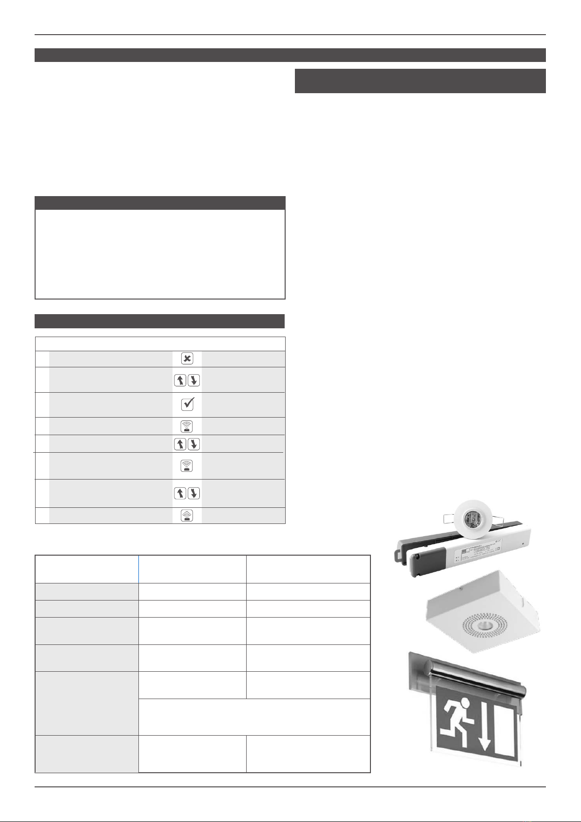
SPECTOXT EMERGENCY MODULES
FAU LT ELP TRIDONIC MACKWELL
Normal mode Green LED - ON Green LED - ON Green LED - ON
(Pulses every 10 seconds)
Commissioning Green LED - slow ash Green LED - ON Green LED - slow ash
Function test Green LED - fast ash Green LED - fast ash Green LED - fast ash
Duration test Green LED - slow ash Green LED - slow ash Green LED - slow ash
Lamp fault/open circuit/short circuit
Red LED - ON Red LED - ON Red LED - fast ash
Battery fault Red LED - slow ash Red LED - slow ash Red LED - slow ash
Charge fault/Circuit fault Red LED - fast ash Red LED - fast ash Red LED - fast ash
Emergency mode LED OFF LED OFF LED OFF
Identication Red/Green LED -
slow ash
Red/Green LED -
slow ash
Red/Green LED -
slow ash
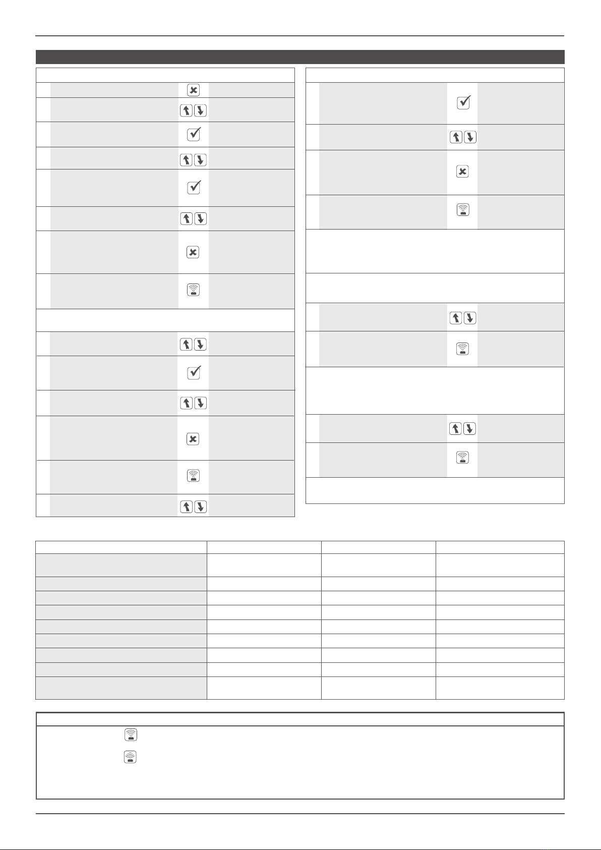
TO PROGRAM SPECTO-XT LUMINAIRE
FUNCTION BUTTON DISPLAY
1Switch on the Programmer IRPR
2Scroll to the <Specto-XT>
<Specto-XT Emergency> menu <Emergency>
3Select the menu download all
<Specto-XT Emergency> (Specto-XT only)
4Use the scroll buttons, to nd building: 1
building address address 1-254
20 Use the scroll buttons, to nd join radio
join radio network network
10 Use the scroll buttons, to nd rf transmit: di
rf transmit enable/disable
To exit the setting mode press
(Esc). The new selected value building: 12
7will now be displayed on the address 1-254
rst line
To exit the setting mode press
(Esc). The new selected value radio LED: di
18 will now be displayed on the enable/disable
rst line
To exit the setting mode press
(Esc). The new selected value rf transmit: en
13 will now be displayed on the enable/disable
rst line
Select this parameter. Option
5 name and current status are building: 1*
now displayed on the top line address 1-254
Select this parameter. Option
11 name and current status are rf transmit: di*
now displayed on the top line enable/disable
Select this parameter. Option
16 name and current status are radio LED: en
now displayed on the top line enable/disable
The (Send) button will now
8 update the chosen parameter building: 12
in the luminaire Sending......OK
The (Send) button will now
19 update the chosen parameter radio LED: di
in the luminaire Sending......OK
The (Send) button will now
14 update the chosen parameter rf transmit: en
in the luminaire Sending......OK
FUNCTION BUTTON DISPLAY
Now all parameters are memorised in the Luminaire.
Each luminaire can have unique parameters if required.
6Use the scroll buttons, to select building: 12*
the required address number address 1-254
15 Use the scroll buttons, to radio LED: en
nd Radio LED enable/disable
12 Use the scroll buttons, to select rf transmit: en*
the required parameter enable/disable
17 Use the scroll buttons, to select radio LED: di*
the required parameter enable/disable
9Repeat these steps above to set the group address and device
address at each luminaire and area as required.
Check that all transmitted parameters have been
conrmed by a Sending..... OK, otherwise correct
programming cannot be guaranteed.
The (Send) button will now
21 join the luminaire to the join radio net-
network Sending......OK
The (Read) button will now
23 read the UDID issued to read unique
the luminaire Reading......OK
The indicator will now ash blue. If the luminaire joins
successfully the indicator will turn amber and ash 10 times.
The luminaire is now issued its UDID from the Gateway.
To check the UDID is correct follow the below steps.
Check that the UDID displayed on the screen is correct. If not
please contact our Technical Department for assistance.
22 Use the scroll buttons, to nd read unique
read unique device ID device ID: non
STATUS AND ERROR MESSAGES
When the Send Button is pressed, Sending . . . . . appears on the bottom line of the display. If the transmission is successful, OK appears briey on
the right hand side of the bottom line.
When the Read Button is pressed, Reading . . . . . appears on the bottom line. If the reception is successful, OK appears briey on the right hand side
of the bottom line.
In both conditions, the programmer
will attempt data transfer three times, shown as #1 followed by #2 followed by #3 on the bottom
line. If, after 3 attempts, the transfer of data is not successful, Link Error appears on the bottom line. Possible causes could be that the programmer isn’t
being pointed directly at the Luminaire, is too far away, or is being masked by IR from the lamps within the luminaire. Resolve the issue and try again.