PLOSCMKNX
Ceiling Mount Universal Sensor
INSTALLATION MANUAL
PLOS-CM-KNX Network Connections
KNX cable connected to sensor.
The sensor has been designed for the KNX network
to loop in and then loop out to the next device. The
dierent KNX network devices can be connected in
any order along the network.
Power down & isolate KNX bus prior to wiring the device
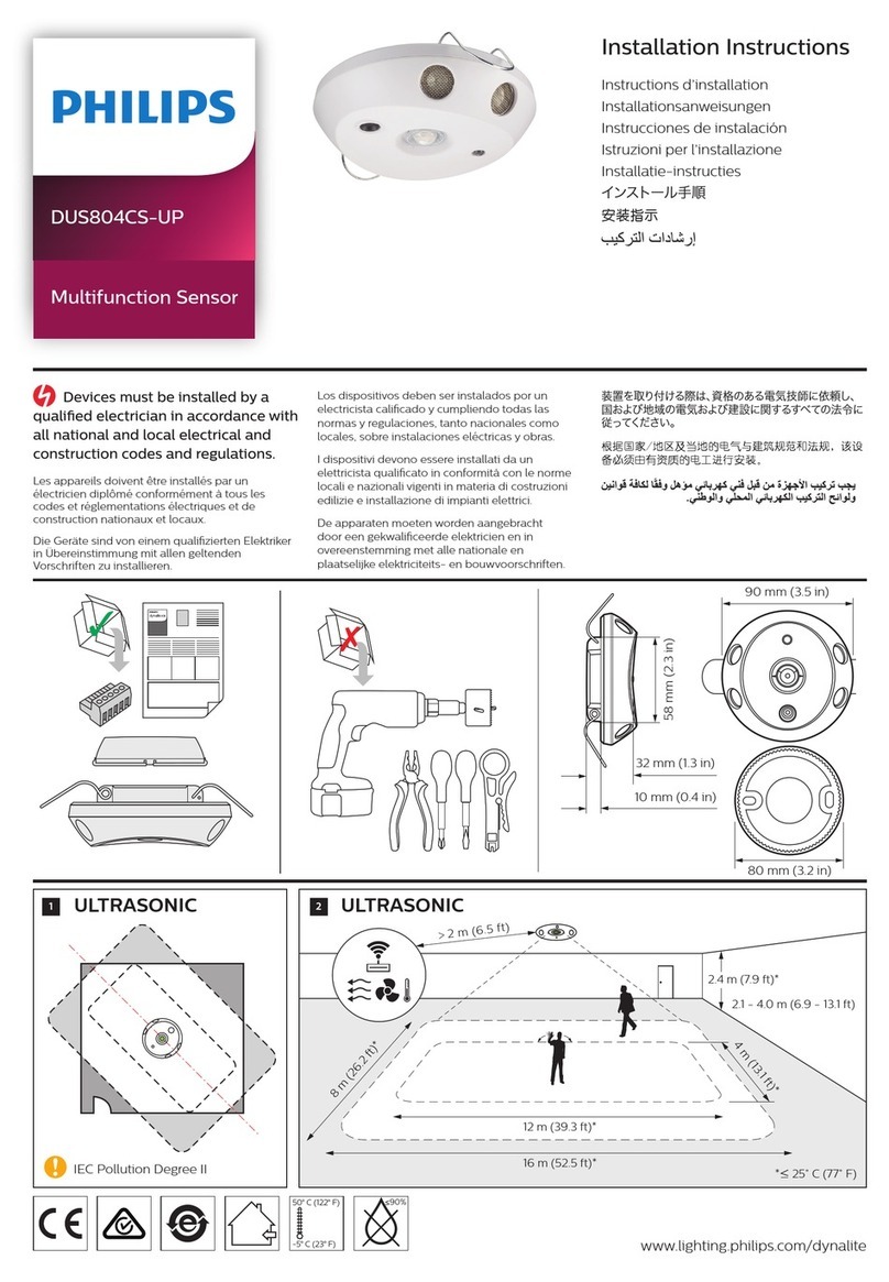
1. Position the sensor so it is between 2.1 and 4.0m from the oor.
Optimum height is 2.4m.
2. Positionthesensor soitisatleast1mawayfromelectricallighting
such as neon and uorescent lights.
3. Positionthesensorastoavoidexposingittodirect sunlight,glare
and heating/cooling sources.
4. Positionthesensorwherepedestriantracislikelytowalkacross
the detection zones (see motion detection coverage diagram).
5. Note that for the PLOS-CM-KNX coverage area is rectangular
(see Motion Detector coverage diagram).
6. Fix the sensor to a rm section of ceiling.
7. For programming instructions refer to the Philips LightMaster
Commisiioning guide.
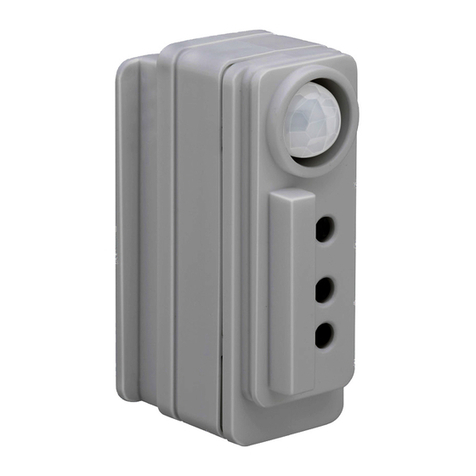
PIR sensor
Click-up bezel for
motion shield
KNX programming
push button and LED
Light level sensor
Data Cable Termination
KNX TP1 cable termination:
1. Strip-o between 25 - 40mm of outer jacket.
2. Cut shield, synthetic foil and tracer ush to the outer jacket.
3. Cut yellow-white pair if unused, insulate ends.
4. Apply a layer of wide insulating tape to cover the remaining
exposed foil and cut area. Approx. 20mm of red-black pair
shall be left exposed for termination.
5. Strip 5 to 6mm of insulation on both red and black wires.
6. Insert wires to the color matching KNX terminal respecting
the polarity (red +, black -).
7. Ensure wires are segregated and fully inserted with no
exposed copper outside terminals to prevent shorts.
TP1 cable shield termination to Earth can improve noise
immunity. It is not mandatory except where a specic
application and/or the local wiring rules require it.
For future reference it’s recommended to place a marker on the
cable indicating“KNX TP1” or “BUS”with the area and line ID.
KNX Bus Permanent
Connections
