Orion TeleTrack 9441 User manual

INSTRUCTION MANUAL
IN 295 Rev. C 02/09
Providing Exceptional Consumer Optical Products Since 1975
Customer Support (800)-676-1343
E-mail: [email protected]
Corporate Offices (831)‑763‑7000
89 Hangar Way, Watsonville, CA 95076
Orion®TeleTrackTM
Altazimuth Tracking Mount
#9441

2
Figure 1. The TeleTrack Altazimuth Tracking Mount
1⁄4”-20 L-bracket
Hand Controller
Altazimuth Fork Arm
Tripod

3
1. Parts List
Qty. Description
1 Hand controller
1 Adjustable tripod
1 Fork arm
1 L-bracket with 1⁄4"-20 adapter
1 Snap cable
2. Assembly
The TeleTrack Mount comes partially assembled and can
become operational in a matter of minutes. It is packaged
in one reusable shipping carton. Remove all parts from the
box. Make sure all the parts listed In Section 1 are present.
Remember to save all the shipping containers so that they
can be used to transport the mount. In the unlikely event that
you need to return the mount, you must use the original pack-
aging.
Refer to Figures 1, 2, and 3 during assembly.
1. Remove the tripod from its box. Note that each leg has
two telescoping sections. To extend each leg, loosen the
leg lock lever by rotating it counterclockwise, then extend
the leg. When it has been extended to the desired length,
rotate the leg lock lever clockwise until tight. Before plac-
ing an instrument on the mount, it is a good idea to press
down on the tripod to make sure the legs are locked
securely and will not give way under the instrument’s
weight.
2. The TeleTrack’s tripod has a wide stance for enhanced
stability. The widest stance is achieved when the leg brace
is as far down as it will go on the elevator shaft housing.
The leg brace lock knob should be tightened to secure the
stance.
If you are using the tripod in a confined space, the stance
can be narrowed by loosening the leg brace lock knob and
pushing the legs closer together. Re-tighten the lock knob
to secure the legs in the new position. Be aware that the
tripod will become more prone to tipping as its stance is
narrowed. Be very careful when mounting an instrument
with an offset, or unwieldy, center of gravity on the tripod,
especially if it begins to approach the 9 lb. weight limit.
3. With the tripod secure, the fork arm can be easily attached
using the 3/8"-16 threaded post on top of the tripod mount-
ing platform. Hold the fork arm so its circular base is facing
downward and place it on the 3/8"-16 threaded post gen-
tly. Rotate the entire fork arm assembly clockwise until it
threads completely onto the tripod’s 3/8"-16 threaded post,
and rests securely on the tripod’s mounting platform.
Congratulations on your purchase of a quality Orion product. Your new TeleTrack Altazimuth Tracking Mount allows
high performance support for terrestrial or astronomical observations. The TeleTrack is an “altazimuth” type of mount which can
move in altitude (up and down) and azimuth (left and right) with respect to the ground. Designed for use during day or night,
your TeleTrack mount features a smooth altazimuth fork arm, adjustable tripod, and multi-function hand controller for convenient
operation.
The TeleTrack Altazimuth Tracking Mount is designed for small telescopes, spotting scopes and cameras. The weight of the
instrument supported by the mount should not exceed 9 lbs. The mount will also work best with short tube optical systems no
longer than 15" (380mm).
These instructions will help you set up and properly use your TeleTrack mount. Please read them over thoroughly before getting
started. It may take a few observing sessions to become familiar with all the features of the TeleTrack mount, so keep this manual
handy until you have mastered your mount’s operation.
Figure 2. The TeleTrack Tripod
3/8"-16 Threaded Post
Elevator Shaft
Hinged Hand Crank
Leg Brace
Leg Lock Levers
Tripod Mounting
Platform
Elevator Lock Knob
Leg Brace Lock
Knob

4
4. There is a bubble level at the base of the fork arm. To
make the fork arm level, simply adjust each tripod leg up
or down, one at a time, until the bubble rests in the central
black circle of the level. It is not critical that the mount be
precisely level, but if the mount is significantly unlevel, it
may compromise the stablity of the setup.
5. To raise or lower the TeleTrack Mount’s fork arm to a com-
fortable height, first loosen the elevator lock knob on the
tripod, then use the hinged hand crank to move the eleva-
tor shaft up or down. Re-tighten the elevator lock knob to
secure the instrument at the new height. The mount will be
most stable when the elevator shaft is not extended.
6. The TeleTrack’s hand controller has a modular plug at
the end of its cord. To attach the hand controller to the
TeleTrack, plug the connector into the “HC” jack at the
base of the mount’s fork arm (see Figure 4). Push the plug
into the jack until it clicks into place. Make sure not to con-
fuse the “HC” jack with the “AUX” jack. The “AUX” jack is
not used for normal operation of the mount.
Note: Do not attempt to reposition the altitude or azimuth
of the mount by hand! Doing so can damage the gears and
motors within the mount.
3. Powering the
TeleTrack Mount
The TeleTrack mount can be powered by 8 AA batteries, an
optional 12V DC power supply, or an optional AC adapter.
The mount’s power requirement is 12 volts DC nominal with a
maximum voltage of 16 volts and a minimum of 8 volts.
Powering by AA Batteries
For maximum portability, the TeleTrack mount features a
battery compartment that holds eight (8) AA batteries (user
supplied). To open the compartment, press down on the black
battery compartment latch gently and lift the cover off. You
will find two separate battery holders that hold 4 AA batteries
each. For easiest installation, detach each battery holder and
insert your AA batteries until each holder is full. Be sure to ori-
ent the batteries as indicated on the battery holder. Reattach
the filled battery holders securely using the snap connectors
and close the battery compartment by pressing its cover down
gently until its latch clicks. Power the TeleTrack on by pressing
the red on/off switch to the “on” position.
Powering by Rechargeable Battery
For optimal results, we recommend using a portable recharge-
able battery like the Dynamo or Dynamo Pro available from
Orion. These DC batteries will power the mount far longer
than standard AA batteries. Make sure your rechargeable
battery is tip positive and capable of producing continuous
current with a minimum of 2 amps.
If you are using a portable battery like the Orion Dynamo, use
the Dynamo’s supplied 12V DC power cable (cigarette lighter
plug on one end, standard 12V DC power plug on the other
end) to connect the battery to the “12V DC IN” power jack on
the side of the mount. Make sure the Dynamo’s power switch
is in the “on” position after connecting. Power the TeleTrack on
by pressing the red on/off switch to the “on” position.
Figure 3. The TeleTrack Mount Fork Arm Head
Dovetail Mount
1⁄4"-20 L-bracket
Bubble Level
Battery Compartment
Battery Compartment Latch
Figure 4. The TeleTrack Mount Control Panel
Snap
Cable Jack
12V DC IN Jack
12V DC
OUT Jack
On/Off Switch
Circular Base
Dovetail Lock Knob
AUX Jack
HC Jack

5
Powering by AC Adapter
In addition, the mount can be powered by an AC adapter rated
at 12V DC, 750mA, tip positive. Plug the adapter cord into the
DC power jack for operation. Power the TeleTrack on by press-
ing the red on/off switch to the “on” position.
Note: Never plug an external power supply cord into the
“12V DC OUT” jack accidentally. This may damage the AA
batteries inside the battery compartment, and possibly dam-
age the mount itself.
Power Output
Unlike many mounts in its class, the TeleTrack Mount will
provide power output for accessories like digital cameras or
camcorders. It accepts a DC power plug (tip positive) and
provides 12V DC power output. To power a 12V accessory
with the TeleTrack, simply plug the accessory’s 12V DC power
cable into the “12V DC OUT” jack on the side of the mount.
4. Attaching a Telescope
or Camera to the TeleTrack
Mount
A. USING THE L-BRACKET
Your TeleTrack Mount comes with a convenient L-bracket
(see Figure 5) that provides coupling to the mount with the
standard 1⁄4"-20 threaded hole found on most cameras,
camcorders, and many telescopes.
Attaching the L-bracket to the Mount
The L-bracket has a short dovetail plate that slides into the
corresponding dovetail mount on the fork arm. The other
section of the L-bracket has a foam-padded base for your tele-
scope or camera. Attaching your instrument to the L-bracket
is accomplished with the 1⁄4"-20 threaded post.
Inserting the L-bracket
Insert the dovetail plate of the L-bracket into the dovetail
mount, making sure that it is oriented as shown in Figure 3.
Then tighten the dovetail lock knob until snug. Now you are
ready to attach your small telescope, camera, or camcorder
directly to the 1⁄4"-20 threaded post of the L-bracket.
Attaching an Instrument to the L-bracket
With the foam-padded base of the L-bracket facing upward,
gently place the 1⁄4"-20 threaded hole in your optical instru-
ment onto the 1⁄4"-20 threads on the L-bracket. Turn the
black knurled knob so the 1⁄4"-20 threaded post completely
engages the 1⁄4"-20 threaded hole in your telescope, spotting
scope, or camera. Tighten by rotating the tightening lever on
the underside of the L-bracket until secure.
B. USING A TELESCOPE’S DOVETAIL MOUNTING
PLATE
If your telescope is equipped with a standard dovetail
mounting plate, you do not need to use the L-bracket to
attach it to the mount. The dovetail plate fits directly into
the TeleTrack’s dovetail mount, providing a very stable and
direct connection.
Simply insert the telescope’s dovetail mounting plate
directly into the dovetail mount, then tighten the dovetail
lock knob until snug.
C. INSTRUMENT ORIENTATION
In order to utilize the astronomical tracking and “cruise”
features of your TeleTrack mount (described later in this
manual), be sure to attach your telescope so the front end
of the instrument is on the side of the fork arm without the
graduated latitude scale (see Figure 6).
Figure 4. The TeleTrack Mount 1⁄4"-20 L-bracket
1⁄4"-20 Threaded Post
Foam Padded base
Figure 6. Instrument Orientation
Front End of
Telescope
Tightening
Lever
Knurled Knob
Screw
Dovetail
Plate
Latitude Scale

6
5. Using the Hand
Controller
This section describes the basic hand controller procedures
needed to operate the TeleTrack mount. These procedures
are grouped into three categories: 1) directional movement,
2) astronomical tracking, and 3) “cruise” modes (see Figure
7). The directional movement section deals with simple move-
ment of the mount for browsing terrestrial or astronomical
targets. The astronomical tracking section discusses how to
set up the mount for tracking objects in the night sky as the
Earth rotates. The cruise modes section describes the pro-
cess of selecting up to 6 set positions and the various modes
of “cruising” between them.
The buttons of the TeleTrack hand controller will illuminate
when pressed to indicate operation. If a button combination
is entered, all the pressed buttons will illuminate to indicate a
successful operation entry. If there is any type of communica-
tion error between the hand controller and the TeleTrack, all
the LEDs will flash.
Speed Buttons
The three buttons located near the top of the hand controller
(“GUIDE”, “SLOW”, AND “FAST”) are used to set the slewing
speed of the mount.
Directional Buttons
The directional buttons allow complete control of the mounted
optical instrument’s position during slewing or tracking. The
“LEFT” and “RIGHT” directional buttons control movements
about the azimuth axis. The “UP” and “DOWN” directional but-
tons control movements about the altitude axis.
Numerical Buttons
The speed and directional buttons are also numbered 1-6
(the “7” button is not used as a numerical button). These but-
tons are used to store user-defined positions in cruise mode,
which is discussed later in this manual.
Cruise Buttons
The two buttons near the bottom of the hand controller (“SET”
and “GO”) will move the mount to preselected targets, the
selection of which is discussed in the “Cruising Modes” sec-
tion of this manual.
A. DIRECTIONAL MOVEMENT (SLEWING)
Your TeleTrack mount can make sweeping motions across
land and sky, or minute adjustments to center your target.
The directional buttons on the hand controller control the
movement of the mount in two axes, altitude (up/down)
and azimuth (left/right).
The relative speed of directional movement can be con-
trolled using the three speed buttons near the top of the
hand controller. Each speed button sets the slewing rate
of the instrument based on multiples of sidereal rate (the
speed in which objects appear to migrate across the night
sky). The “GUIDE” button sets the slewing rate to 32x side-
real rate. The “SLOW” button sets the slewing rate to 64x
sidereal rate. The “FAST” button sets the slewing rate to
800x sidereal rate.
The button of the selected slew speed will illuminate once
it is pressed. Once you have selected your preferred slew-
ing speed, use the directional buttons to move the mount.
Note: Never slew a telescope when another person
is looking in the eyepiece. The mount can move at fast
slew speeds and may hit the observer in the eye.
B. ASTRONOMICAL TRACKING
In addition to being able to slew the telescope with the
hand controller’s directional buttons, the TeleTrack mount
can also track a celestial object as it appears to move
across the night sky.
Setting the Latitude
In order to track celestial objects accurately, your TeleTrack
mount requires a simple procedure to set the geographical
latitude of your observing location. This procedure can be
performed indoors, before taking the TeleTrack out under the
night sky. To set your latitude for astronomical tracking, follow
these steps:
1. Determine the latitude of your observing location. You may
need to consult a geographical atlas to do this.
2. Power on the TeleTrack mount.
Figure 7. The TeleTrack Mount Hand Controller
Speed
Buttons
Directional
Buttons
Cruise Buttons
Hand Controller Cable

7
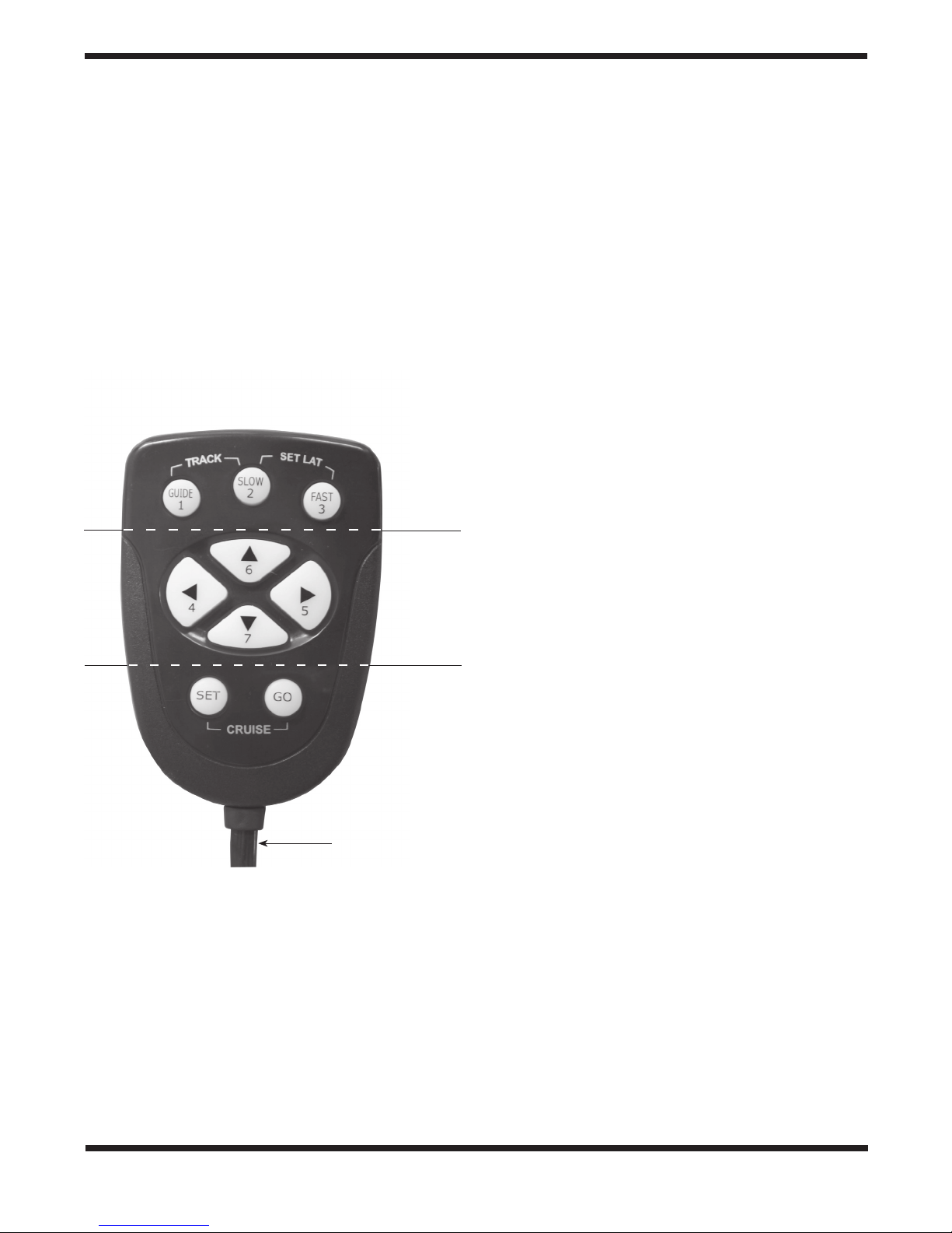
3. Press the “FAST” speed button then the “UP” or “DOWN”
directional buttons to roughly level the telescope.
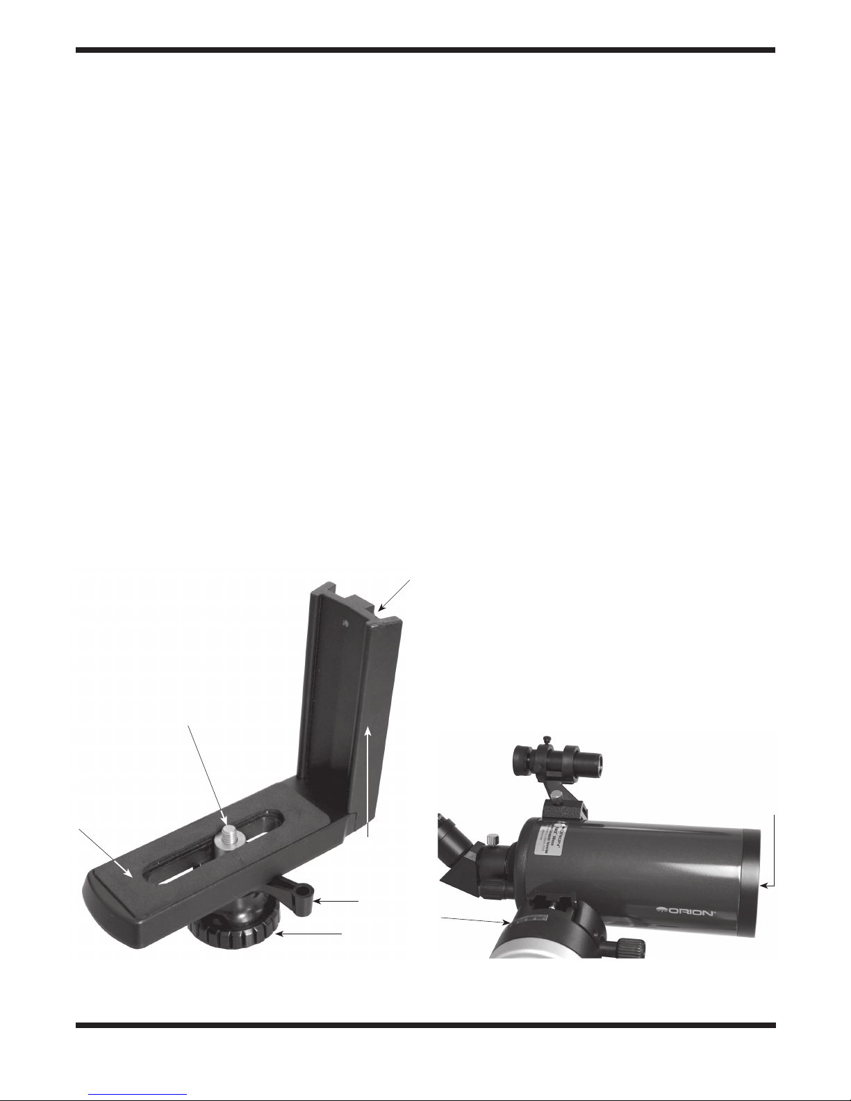
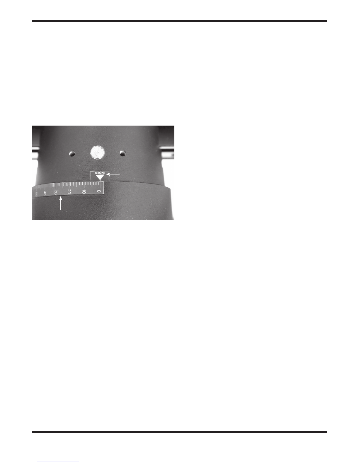
4. There is a latitude scale near the top of the TeleTrack fork
arm with a value range from 0° to 90°. One of the three
latitude indicator arrows should be pointing close to the “0”
mark on the latitude scale (see Figure 8). If not, remove
the L-bracket or dovetail plate from the mount, and use
the “UP” or “DOWN” buttons to rotate the mount 180° in
altitude, then reattach the telescope. (When reattaching
the telescope, keep in mind that the objective lens of the
telescope should be on the side of the mount without the
latitude scale, see Figure 6).
5. Now that the indicator arrow is close to the 0 on the lati-
tude scale, press the “SLOW” speed button and slew the
mount slightly using the “UP” and “DOWN” buttons until
the latitude indicator arrow is precisely lined up with the 0
mark on the latitude scale.
Note: To reduce the chances of motor backlash error, make
your final directional adjustment here with the “UP” directional
button.
6. Turn off the TeleTrack mount, wait a few seconds, then
turn the mount back on.
7. Use the speed buttons and “UP” and “DOWN” directional
buttons on the hand controller to move the telescope until
the latitude indicator arrow is lined up with the value on the
latitude scale corresponding to the latitude of your observ-
ing location. For example, if you are at 37° North latitude,
slew the mount so the indicator arrow lines up with the 37
mark on the latitude scale.
Note: To reduce the chances of motor backlash error, make
your final directional adjustment here with the “UP” directional
button.
8. Finally, press the “FAST” and “SLOW” buttons simultane-
ously to store your latitude into the TeleTrack system.
Now you are ready to observe celestial objects and track their
apparent migration across the night sky. The TeleTrack will
remember your latitude setting even after it is powered off.
Note: For Southern Hemisphere operation, the procedure to
set your latitude is similar to the above, but with the 0 mark
and latitude value reversed. First slew the mount so the indi-
cator arrow points to the value of your latitude on the scale,
then power off the mount. Now, power on the mount and
slew it until the indicator arrow lines up with the 0 mark on
the latitude scale, then press the “FAST” and “SLOW” buttons
simultaneously.
Initial Positioning
Now that the TrueTrack knows the latitude of your observing
site, you are ready to use it for astronomical observation. But
first, the mount must be set so it is powered on in its initial
“home” position.
1. Power the mount on, and slew the mount using the “UP”
and “DOWN” buttons so the telescope is roughly level.
One of the two latitude indicator arrows should be close to
the 0 mark of the latitude scale.
2. Use the “UP” and “DOWN” buttons to precisely level the
telescope. Use a carpenter’s level along the telescope’s
tube for best precision.
Note: To reduce the chances of motor backlash error, make
your final directional adjustments here with the “UP” direc-
tional button.
3. Now, use the “LEFT” and “RIGHT” buttons to slew the tele-
scope so that it is pointing North. Use Polaris (the North
Star) as a reference, if possible. If Polaris is not visible
from your observing site, then consult a compass.
Note: To reduce the chances of motor backlash error, make
your final directional adjustments here with the “RIGHT” direc-
tional button.
4. Power the TeleTrack mount off.
The TeleTrack is now in its home position. For astronomical
tracking to function properly, the mount must be powered on
in its home position.
Finding and Tracking a Celestial Object
Once your TeleTrack mount has been aligned for astronomical
tracking, you can pick a celestial object to observe and track.
1. Power the TeleTrack mount on. Make sure it is in its home
position before doing this.
2. Choose a celestial object from a star map, planetarium
software, or planisphere. Note the constellation in which
the object resides. Set your TeleTrack mount slew speed to
“FAST” and slew your telescope in the general direction of
the constellation.
3. Once you are close to the target, set your slew speed to
“SLOW” or “GUIDE” and carefully adjust the position of
your telescope while looking through the telescope’s find-
er scope until the target object is centered in the finder
scope’s field of view.
4. If your finder scope is properly aligned with your tele-
scope, you should now be able to magnify the object by
inserting a wide-field eyepiece (25mm or greater) into
Figure 8. Setting the Latitude
Indicator Arrow
Latitude Scale

8
your telescope and viewing through it. If the object is not
centered in the eyepiece, make careful adjustments using
the “GUIDE” slew speed and directional buttons until the
object is centered.
5. Once you have centered the target object in your eyepiece,
you can track it’s apparent migration across the night sky.
To activate tracking press the “GUIDE” and “SLOW” speed
buttons simultaneously. The mount will now track the cen-
tered object at sidereal rate. One of the three speed but-
tons will begin to blink, indicating that tracking is activat-
ed.
Making Directional Adjustments While Tracking
Your TeleTrack mount features tracking slew speeds which
allow you to make fine adjustments to the position of the
mount while tracking. These speeds are much slower than the
speeds when tracking is not activated.
With tracking activated:
•Pressthe“GUIDE”speedbuttontosetthedirectional
buttons to slew the mount at 1x sidereal rate. The
“GUIDE” button will blink to indicate operation.
•Pressthe“SLOW”speedbuttontosetthedirectionalbut-
tons to slew the mount at 4x sidereal rate. The “SLOW”
button will blink to indicate operation.
•Pressthe“FAST”speedbuttontosetthedirectionalbut-
tons to slew the mount at 8x sidereal rate. The “FAST”
speed button will blink to indicate operation.
Canceling Astronomical Tracking
To stop tracking a celestial object, simply press the “GUIDE”
and “SLOW” speed buttons simultaneously. The speed button
with which you have set the slew speed will stop blinking and
remain steadily illuminated to indicate that tracking has been
canceled. The speed buttons will now operate at their regular
(i.e. non-tracking) speed rates.
C. CRUISE MODES
There are three “cruise” modes which enable your
TeleTrack mount to automatically slew to up to 6 pre-set
positions. Cruise modes are for use on stationary terrestri-
al targets. Cruise modes are not recommended for celes-
tial objects, as they change position over time due to the
rotation of the Earth.
The three different cruise modes are: “GoTo”, “Cruise
and Shoot” and “Cruise and Record”. “GoTo” cruise mode
allows you to automatically slew the mount to any of the
6 positions you have set. “Cruise and Shoot” mode is
designed for use with a digital camera; this mode will auto-
matically slew the mount to all of your pre-set positions and
trigger a camera shutter release at each position. “Cruise
and Record” mode is designed for use with a camcorder
device. The “Cruise and Shoot” and “Cruise and Record”
modes are especially useful for surveillance applications.
NOTE: Be sure to cancel astronomical tracking prior to
setting cruise mode positions or using cruise modes.
Initial Positioning
In order for the TeleTrack to remember the Cruise mode posi-
tions you set after the mount is powered off, it is necessary to
power on the mount when it is in its “home cruise” position. To
position the mount in its home cruise position:
1. Power the mount on, and slew the mount using the “UP”
and “DOWN” buttons so the telescope is roughly level.
One of the two latitude indicator arrows should be close to
the 0 mark of the latitude scale.
2. Use the “UP” and “DOWN” buttons to precisely center the
indicator arrow on the 0 mark of the latitude scale.
6. Now, use the “LEFT” and “RIGHT” buttons to slew the tele-
scope so that it is pointing at a stationary reference point.
7. Power the TeleTrack mount off.
The TeleTrack is now in its home cruise position. For the
mount to successfully return to any pre-set cruise positions,
the mount must be powered on in the home cruise position.
The tripod must also be in the same location as when the
cruise mode positions were set.
Setting Mount Positions for Cruise Modes
1. Set the mount to its home cruise position, and power the
mount on.
2. Use the directional buttons to slew the mount to the desired
position.
3. Press and hold the “SET” button, then one of the numeri-
cal buttons from 1-6 (the “7” button is not to be used for
storing positions).
4. Repeat steps 1 and 2 for up to five additional pre-set posi-
tions.
Using “GoTo” Cruise Mode
Press and hold the “GO” button and press the numerical but-
ton which corresponds with the pre-set mount position you
wish to go to. All of the hand controller buttons will illuminate
to indicate a successful operation choice. While the mount is
slewing to the pre-set position, the “GO” button will remain
illuminated and the numerical button will blink. Once the pre-
set position has been reached, both buttons will dim, and the
current slew speed button will illuminate.
Speed Button Guide Slow Fast
Slew Speed
without
Tracking
Slew Speed
with Tracking
Activated
32x
sidereal
rate
64x
sidereal
rate
800x
sidereal
rate
1x
sidereal
rate
4x
sidereal
rate
8x
sidereal
rate

9
Erasing a Set Mount Position for Cruise Modes
If you want to permanently erase a cruise mode position that
has already been set:
1. Return the mount to its home cruise position.
2. Turn the power off and then turn it back on again.
3. Hold down the “SET” button and press the numeric key cor-
responding to the position you want to erase.
The mount will recognize that you have erased the previously
set position, and will bypass this position during subsequent
cruise mode operation.
Using “Cruise and Shoot” Mode
If you attach a digital camera with a shutter release jack to your
telescope, or directly to the TeleTrack mount, you can utilize
the shutter release feature of the “cruise and shoot” mode. To
electronically connect your camera to the TeleTrack, plug one
end of the included snap cable into the snap cable jack on the
TeleTrack mount (see Figure 4), then plug the other end of the
cable into your camera’s shutter release jack (see Figure 9).
Once you have connected your camera to the mount's SNAP
cable jack, press the “SET” and “GO” buttons simultaneously
to initiate “cruise and shoot” mode. The TeleTrack mount will
automatically slew to all of the pre-set positions (starting with
position 1) pausing briefly (approximately 15 seconds) at each
position to trigger the shutter release of your camera.
While in “cruise and shoot” mode, the “SET” and “GO” buttons
will remain illuminated as the mount slews to your pre-set posi-
tions. The numerical button of the pre-set position will blink as
the mount slews to it. “Cruise and shoot” mode will repeat its
cycle after approximately 3 minutes. You can bypass this wait-
ing period by pressing the “FAST” speed button.
Using “Cruise and Record” Mode
If you attach a camcorder to your telescope, or directly to the
TeleTrack mount, you can utilize the “cruise and record” mode.
Press both the “GO” and “DOWN” buttons simultaneously to
initiate “cruise and record” mode. The TeleTrack mount will
automatically slew to all of the pre-set positions (starting with
position 1) and pause very briefly (approximately 3 seconds) at
each position. The “GO” and “DOWN” buttons will remain illu-
minated while in “cruise and record” mode and the numerical
button of the pre-set position will blink as the mount slews to
it. “Cruise and record” mode will repeat its cycle until stopped
with the hand controller.
Cancelling Cruise Modes
To cancel any of the cruise modes or to stop movement of
the mount during cruise modes, press both the “RIGHT” and
“DOWN” directional buttons simultaneously. The mount will
stop all movement and the current slew speed button will illu-
minate steadily.
6. Care and Cleaning of the
TeleTrack Mount
If your TeleTrack mount accumulates dew while operating, dry
it completely with a soft cloth after use. Clean the mount with
mild household detergent and a soft cloth. The jacks can be
kept free of dust using a blower bulb or a canister of com-
pressed air.
Keep the mount in a clean and dry environment when not in
use. Do not store the mount outdoors.
To prevent damage, we recommend removing your telescope
or optical instrument from the mount when transporting.
7. Technical Specifications
Mount: Altazimuth, electronic slewing for
both axes of motion, sidereal track-
ing
Tripod: Aluminum, minimum height 20.5",
maximum height 54.5"
Weight (fully assembled): 9 lbs.
Power requirements: 12 volts DC nominal, 750mA maxi-
mum current draw, tip positive, can
run off of 8x internal AA batteries
Slew speeds: 800x/64x/32x sidereal rate, 8x/4x/
1x sidereal rate with sidereal track-
ing activated
Sidereal tracking Northern or Southern Hemisphere
operation:
Figure 9. Connecting a Camera to the TeleTrack Mount
Fork Arm Head
SNAP Cable
Jack
Camera
SNAP Cable

10
This device complies with Part 15 of the FCC Rules. Operation
is subject to the following two conditions: (1) this device may
not cause harmful interference, and (2) this device must
accept any interference received, including interference that
may cause undesired operation.
Changes of modifications not expressly approved by the party
responsible for compliance could void the user’s authority to
operate the equipment.
Note: This equipment has been tested and found to comply
with the limits for a Class B digital device, pursuant to Part
15 of the FCC Rules. These limits are designed to provide
reasonable protection against harmful interference in a resi-
dential installation. This equipment generates, uses and
can radiate radio frequency energy and, if not installed and
used in accordance with the instructions, may cause harm-
ful interference to radio communications. However, there is
no guarantee that interference will no occur in a particular
installation. If this equipment does cause harmful interference
to radio or television reception, which can be determined by
turning the equipment off and on, the user is encouraged to
try to correct the interference by one or more of the following
measures:
Reorient or relocate the receiving antenna.
Increase the separation between the equipment and
receiver.
Connect the equipment into an output on a circuit different
from that to which the receiver in connected.
Consult the dealer or an experienced radio/TV technician
for help.
A shielded cable must be used when connecting a periph-
eral to the serial ports.

11

12
Orion Telescopes & Binoculars
89 Hangar Way, Watsonville, CA 95076
Customer Support Help Line (800)‑676‑1343 • Day or Evening
One-Year Limited Warranty
This Orion TeleTrack Altazimuth Tracking Mount is warranted against defects in materials or workman-
ship for a period of one year from the date of purchase. This warranty is for the benefit of the original
retail purchaser only. During this warranty period Orion Telescopes & Binoculars will repair or replace, at
Orion’s option, any warranted instrument that proves to be defective, provided it is returned postage paid
to: Orion Warranty Repair, 89 Hangar Way, Watsonville, CA 95076. If the product is not registered, proof
of purchase (such as a copy of the original invoice) is required.
This warranty does not apply if, in Orion’s judgment, the instrument has been abused, mishandled, or
modified, nor does it apply to normal wear and tear. This warranty gives you specific legal rights, and
you may also have other rights, which vary from state to state. For further warranty service information,
contact: Customer Service Department, Orion Telescopes & Binoculars, 89 Hangar Way, Watsonville, CA
95076; (800)-676-1343.
Table of contents
Other Orion Accessories manuals

Orion
Orion StarShoot 51450 User manual

Orion
Orion SKYLINE 5673 User manual

Orion
Orion StarShoot AutoGuider User manual

Orion
Orion 6001 User manual

Orion
Orion OT-T07 User manual

Orion
Orion AccuFocus 7395 User manual

Orion
Orion RKS250F1-S User manual

Orion
Orion 8727 User manual

Orion
Orion HCCA G27902 User manual

Orion
Orion EQ-1 Equatorial Mount 9011 User manual