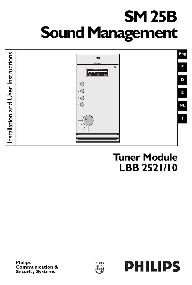
Philips LBB 2541/10 Guide

Philips
Communication,
Security & Imaging
Recordable Message Module
LBB 2541/10
SM 25B
Sound Management
Digital messages
RMM
Mode
Start/Stop
Message
Play
Record
Monitor
Eng
F
D
E
NL
I
Installation and User Instructions

Eng Installation and User Instructions.....................................................................................................................5
FInstruction d'installation et mode d'emploi..................................................................................................16
DInstallations- und Bedienungsanleitung..........................................................................................................28
EInstrucciones de instalación y de usuario.....................................................................................................40
NL Installatie-instructies en gebruiksaanwijzing.................................................................................................52
IIstruzioni per l'installazione e l'uso ................................................................................................................64
2

3
Eng
IMPORTANT SAFEGUARDS
1. Read Instructions - All the safety and operating instructions should be read before the unit is
operated.
2. Retain Instructions - The safety and operating instructions should be retained for future ref-
erence.
3. Heed Warnings - All warnings on the unit and in the operating instructions should be
adhered to.
4. Follow Instructions - All operating and use instructions should be followed.
5. Cleaning - Unplug the unit from the outlet before cleaning. Do not use liquid cleaners or
aerosol cleaners. Use a damp cloth for cleaning.
6. Attachments - Do not use attachments not recommended by the product manufacturer as
they may cause hazards.
7. Water and Moisture - Do not use this unit near water - for example, near a bath tub, wash
bowl, kitchen sink, or laundry tub, in a wet basement, near a swimming pool, in an unpro-
tected outdoor installation, or any area which is classified as a wet location.
8. Accessories - Do not place this unit on an unstable stand, tripod, bracket, or mount. The
unit may fall, causing serious injury to a person and serious damage to the unit. Use only
with a stand, tripod, bracket, or mount recommended by the manufacturer, or sold with the
product. Any mounting of the unit should follow the manufacturer’s instructions, and should
use a mounting accessory recommended by the manufacturer. Do not install near any heat
sources such as radiators, heat registers, stoves or other apparatus. An appliance and cart
combination should be moved with care. Quick stops, excessive force, and uneven surfaces
may cause the appliance and cart combination to overturn.
9. Ventilation - Openings in the enclosure, if any, are provided for ventilation and to ensure
reliable operation of the unit and to protect it from overheating. These openings must not
be blocked or covered. This unit should not be placed in a built-in installation unless proper
ventilation is provided or the manufacturer’s instructions have been adhered to.
10. Power Sources - This unit should be operated only from the type of power source indicated
on the marking label. If you are not sure of the type of power supply you plan to use, consult
your appliance dealer or local power company. For units intended to operate from battery
power, or other sources, refer to the operating instructions.
11. Grounding or Polarization - This unit may be equipped with a polarized alternating-current
line plug (a plug having one blade wider than the other). This plug will fit into the power out-
let only one way. This is a safety feature. If you are unable to insert the plug fully into the
outlet, try reversing the plug. If the plug should still fail to fit, contact your electrician to
replace your obsolete outlet. Do not defeat the safety purpose of the polarized plug. Alter-
nately, this unit may be equipped with a 3-wire grounding-type plug, a plug having a third
(grounding) pin. This plug will only fit into a grounding-type power outlet. This is a safety fea-
ture. If you are unable to insert the plug into the outlet, contact your electrician to replace
your obsolete outlet. Do not defeat the safety purpose of the grounding-type plug.
12. Power-Cord Protection - Power-supply cords should be routed so that they are not likely to
be walked on or pinched by items placed upon or against them, paying particular attention to
cords and plugs, convenience receptacles, and the point where they exit from the appliance.
13. Power Lines - An outdoor system should not be located in the vicinity of overhead power
lines or other electric light or power circuits, or where it can fall into such power lines or
circuits. When installing an outdoor system, extreme care should be taken to keep from
touching such power lines or circuits as contact with them might be fatal.
14. Overloading - Do not overload outlets and extension cords as this can result in a risk of fire
or electric shock.
15. Object and Liquid Entry - Never push objects of any kind into this unit through openings as
they may touch dangerous voltage points or short-out parts that could result in a fire or
electric shock. Never spill liquid of any kind on the unit.
16. Servicing - Do not attempt to service this unit yourself as opening or removing covers may
expose you to dangerous voltage or other hazards. Refer all servicing to qualified ser
vice
personnel.

4
Eng 17. Damage Requiring Service - Unplug the unit from the outlet and refer servicing to
qualified service personnel under the following conditions:
a. When the power-supply cord or plug is damaged.
b. If liquid has been spilled, or objects have fallen into the unit.
c If the unit has been exposed to rain or water.
d. If the unit does not operate normally by following the operating instructions.
Adjust only those controls that are covered by the operating instructions, as an
improper adjustment of other controls may result in damage and will often require
extensive work by a qualified technician to restore the unit to its normal operation.
e. If the unit has been dropped or the cabinet has been damaged.
f. When the unit exhibits a distinct change in performance--this indicates a need for
service.
18. Replacement Parts - When replacement parts are required, be sure the service technician
has used replacement parts specified by the manufacturer or have the same characteristics
as the original part. Unauthorized substitutions may result in fire, electric shock or other
hazards.
19. Safety Check - Upon completion of any service or repairs to this unit, ask the service
technician to perform safety checks to determine that the unit is in proper operating
condition.
20. Coax Grounding - If an outside cable system is connected to the unit, be sure the cable
system is grounded.
21. Lightning - For added protection of this unit during a lightning storm, or when it is left
unattended and unused for long periods of time, unplug it from the wall outlet and discon-
nect the cable system. This will prevent damage to the unit due to lightning and power-
line surges.

5
Eng
SAFETY PRECAUTIONS
This label may appear on the bottom of the unit
due to space limitations.
THE LIGHTNING FLASH WITH AN
ARROWHEAD SYMBOL, WITHIN
AN EQUILATERAL TRIANGLE, IS
INTENDED TO ALERT THE USER
TO THE PRESENCE OF UN-INSU-
LATED “DANGEROUS VOLTAGE”
WITHIN THE PRODUCT’S ENCLO-
SURE THAT MAY BE OF SUFFIC-
IENT MAGNITUDE TO CONSTI-
TUTE A RISK OF ELECTRIC SHOCK
TO PERSONS.
The exclamation point within an equi-
lateral triangle is intended to alert the
user to the presence of important
operating and maintenance (servicing)
instructions in the literature accompa-
nying the appliance.
Note: A note alerts the user or installer to
special installation or operating procedures.
The hand symbol in a circle indicates a
note.
Caution: Installation should be per-
formed by qualified service personnel
only in accordance with the National
Electrical Code or applicable local
codes.
CAUTION: TO REDUCE THE RISK
OF ELECTRIC SHOCK, DO NOT
OPEN COVERS. NO USER
SERVICEABLE PARTS INSIDE.
REFER SERVICING TO QUALIFIED
SERVICE PERSONNEL.
WARNING: TO PREVENT FIRE OR
SHOCK HAZARD, DO NOT
EXPOSE UNITS NOT SPECIFICALLY
DESIGNED FOR OUTDOOR USE
TO RAIN OR MOISTURE.
COVER REMOVAL
Caution: Power Disconnect. Units
with or without ON-OFF switches
have power supplied to the unit
whenever the power cord is inserted
into the power source; however, the
unit is operational only when the
ON-OFF switch is in the ON posi-
tion. The power cord is the main
power disconnect for all units.
Caution: External Power Supplies
use only the Recommended Power
Supplies. Power supplies must com-
ply with the requirements of the lat-
est version of IEC 65/VDE 0860. Sub-
stitutions may damage the unit or
cause a fire or shock hazard.
WARNING: REMOVAL OF THE
COVER SHOULD ONLY BE PER-
FORMED BY QUALIFIED SERVICE
PERSONNEL - NOT USER SER-
VICEABLE. THE UNIT SHOULD
ALWAYS BE UNPLUGGED
BEFORE REMOVING THE COVER,
AND REMAIN UNPLUGGED
WHILE THE COVER IS REMOVED.

6
Eng List of abbreviations used in this Installation and User Instructions
Description Type number
ARM Alarm Routing Module LBB 2540/10
B60 60 W Booster Amplifier LBB 2106/00
B120 120 W Booster Amplifier LBB 2112/00
B240 240 W Booster Amplifier LBB 2124/00
BCB Booster Connection Board LBB 2503/00
BGM Background Music
BPS Blank Panel set LBC 1502/00
CS-B Call Station LBC 2500/10
CCC Call Station Connection Cable LBC 1510/10
CSM Call Station Module LBB 2511/10
CX-B Call Station Extension LBC 2502/00
DIL Dual In Line
EXT External
F60 60 W Booster Frame LBB 2006/00
F120 120 W Booster Frame LBB 2012/00
F180D 120 + 60 W dual amplifier Booster Frame LBB 2018/00
F240 240 W Booster Frame LBB 2024/00
FIM Frame Interconnection Module LBB 2505/10
GMM General Mixing Module LBB 2510/10
HGS Hand-grip Set LBC 1501/00
INT Internal
LED Light emitting diode (indicator)
Mic Microphone
MIX Mixing Input Module LBB 2516/10
MXF Module Extension Frame LBB 2500/00
MZS Manual Zone Switch LBB 2550/00
NC Not connected
PCB Printed Circuit Board
PCF Power Consumption Factor
PSM Power Supply Module LBB 2502/10
PTT Press-to-talk (button)
RMM Recordable Message Module LBB 2541/10
TTS Table-top Set LBC 1500/00
TUM Tuner Module LBB 2521/10
ZRM Zone Relay Module LBB 2551/10
How to... page
configure the RMM 10
connect the RMM 10
install the RMM 9
monitor the RMM 14
operate the RMM 12
trouble-shoot the RMM 15
The publisher reserves the right to change data and/or specifications of any equipment men-
tioned in this publication without prior notice. Although every effort is made to ensure that
information is accurate and correct, the publisher is not responsible for damage resulting from
its use or misuse.

7
Eng
CONTENTS
1. Introduction
2. Installation, connection and configuration
2.1 Installing the RMM ............................................................................................................................9
- Installing the RMM in a Booster Frame ..........................................................................................9
2.2 Connecting the RMM.....................................................................................................................10
- Connecting RMM inputs/outputs...................................................................................................10
- Connecting the RMM internal batteries.......................................................................................10
2.3 Configuring the RMM ...................................................................................................................10
- RMM configuration switches...........................................................................................................10
3. Operating the RMM
3.1 Recording a new message...........................................................................................................12
- Recording a message using the GMM/MIX..................................................................................12
- Recording a message using the CS-B/CX-B ................................................................................13
3.2 Deleting a message.........................................................................................................................13
3.3 Playing back a message ................................................................................................................14
- Playing a message remotely.............................................................................................................14
3.4 Monitoring recorded messages using a headphone........................................................14
3.5 Monitoring the status of the RMM..........................................................................................14
3.6 Trouble-shooting the RMM ........................................................................................................15
4. Technical specifications
WARNING: READ THE IMPORTANT SAFETY INSTRUCTIONS BEFORE INSTALLING
THIS EQUIPMENT.
REFERENCE DOCUMENTATION
The following documents are referred to in this installation instructions.
Installation Instructions: Instructions for use:
• Booster Frame 3922 988 52281 • Booster Frames 3922 988 52681
• CS-B 3922 988 53381 • CS-B 3922 988 54681
• CSM 3922 988 53181 • CSM 3922 988 52881
• CX-B 3922 988 53481 • CX-B 3922 988 54781
• GMM 3922 988 52981 • GMM 3922 988 52781
• MIX 3922 988 53081 • MIX 3922 988 54881
• MXF 3922 988 53581

8
Eng 1. INTRODUCTION
The Recordable Message Module (RMM) is for use in the SM 25B Booster Frames or Module
Extension Frame (MXF). It is a digital recorder for recording, monitoring and playing back up to
10 messages with a total playing time of 132 seconds. Up to three additional memory modules
(MSM6685AJS from OKI Semiconductor, contact Philips CSI Sales Support for availability) can
be added to the RMM printed circuit board to increase the total playing time to 528 seconds.
Messages are backed up using four NiCd batteries. Messages are recorded using the GMM/MIX
module or CS-B via the SM 25B system bus. Messages can be remotely activated via the
input/output connector on the rear panel. A block diagram is shown in fig. 1.1.
Note: The RMM internal batteries should be replaced after five years. The batteries should be dis-
connected using jumper PC25 (figure 1.13) if the RMM is not to be used for more than six months.
The RMM is delivered with the batteries disconnected. Refer to section 2.2 for information about con-
necting the batteries for the first time.
Note: Refer also to the Installation Instructions and User Instructions for the Booster Frames, MXF,
GMM, MIX, CS-B, CX-B and CSM.
Front panel (fig. 1.2):
1. Power indicator (green LED) (item 1)
2. Play indicator (green LED) (item 2)
3. Record indicator (red LED) (item 3)
4. Monitor indicator (yellow LED) (item 4)
5. Pre-selected message indicator (7-segment display) (item 5)
6. Mode selector (inset toggle push button) (item 6)
7. Start/stop push button (item 7)
8. Message select push button (item 8)
9. 3.5 mm stereo headphone jack (internally wired for mono) (item 9)
Note: The mode selector button must be pressed using a pointed instrument such as a pen.
Rear panel (fig. 1.3):
1. 15-way input/output connector (item 1)
RMM modes
The RMM can operate in three modes:
• Record - for recording messages
• Play - for playing back pre-recorded messages
• Monitor - for listening to messages via headphones connected to the front panel
Note: The default mode is play. If the RMM is in any other mode, and is not recording or monitoring,
it will revert to play after two minutes if no actions are initiated by the user.
Message inputs
Messages can be recorded using a GMM/MIX or CS-B/CX-B that is connected to the SM 25B
system. The GMM/MIX can receive microphone inputs or line inputs (for example, from a CD
player). In this case, configuration settings in the GMM such as speech filters, compression,
priority and chime apply to any messages recorded. Messages recorded using a GMM are routed
to the RMM via the SM 25B system flat-cable connector. In the case of messages recorded using
a CS-B, configuration settings such as zone setting, priority and chimes apply to any messages
recorded. Messages recorded using a CS-B are routed to the RMM via a CSM module and the
SM 25B system flat-cable connector.
Note: Messages recorded using the CS-B contain zoning information that is passed to the RMM.
However, messages recorded using the GMM/MIX are sent to all zones by default. In this case,
zoning information can be specified using the RMM DIL switches.

9
Eng
Configurable functionality
The RMM can be configured using DIL switches and potentiometers on the PCB. The
following can be configured:
• Priority for each message recorded (from priority 1 to priority 5)
• Zone selection for each message recorded (any combination of 12 zones)
• External indication of message playing for each message input
• Message activation/deactivation properties for each message input
• Overall audio output level and headphone volume level
2. INSTALLATION, CONNECTION AND CONFIGURATION
2.1 Installing the RMM
Installing the RMM in a Booster Frame
WARNING: SWITCH THE EQUIPMENT OFF AND REMOVE THE MAINS PLUG
FROM THE MAINS OUTLET BEFORE OPENING THE EQUIPMENT.
Caution: The RMM is designed to operate safely in a SM 25B Booster Frame or MXF.
Ensure that the Booster Frame or MXF is installed in accordance with the Installation
Instructions supplied with the equipment before installing the RMM.
Supplied with the RMM (LBB 2541/10):
• Installation and User Instructions
Special tools required:
• T10 Torx screwdriver
• T20 Torx screwdriver (for 19-inch rack mounting)
Installation procedure
1. If the RMM is to be mounted in a Booster Frame in a 19-inch rack:
- Switch off and unplug the Booster Frame from the mains (fig. 1.4).
- Loosen the four captive Torx screws 'A' (fig. 1.5).
- Slide the Booster Frame forward until it stops and lift out the cardboard top cover (fig. 1.6).
Note: All positions in the Booster Frame are functionally identical. The RMM may be mounted in any
available position.
Note: At this point, all switches on the PCB are accessible. If the RMM is to be configured, refer to
section 2.3.
2. Insert the RMM and push it completely home (fig. 1.7).
3. Tighten the captive Torx screw on top of the front panel (fig. 1.8, detail A).
4. The SM 25B Booster Frame is connected to the RMM via a flexible 16-pole system cable.
This flat-cable runs from the Booster Frame PCB along the top of the Booster Frame
(fig. 1.9 detail B)
Caution: Unused module positions in the Booster Frame must be covered with a
blanking panel to ensure that the forced air cooling functions correctly (fig. 1.10).
5. Replace the cardboard top cover and slide the Booster Frame back into the 19-inch rack
(or Table-top Housing) and tighten the four Torx screws (fig. 1.11).
Caution: The cardboard top cover must be replaced before sliding the Booster Frame
back into the rack to ensure that the forced air cooling functions correctly.

10
2.2 Connecting the RMM
Caution: When wiring inputs to the RMM in a 19-inch rack, ensure that the cables are
of sufficient length to allow the Booster Frame to be withdrawn on its runners (approx.
30 cm, 12 in.).
Connecting RMM inputs/outputs
Inputs from the GMM/MIX or CS-B are connected via the SM 25B system bus. This connection is
made using the 16-pole flat-cable that runs along the top of the Booster Frame or MXF. Each mes-
sage can be remotely activated via the 15-pole connector on the rear panel. This connector has
separate screw fastenings for remote connections, that are labelled for each message (0 to 9).
Galvanically isolated relay contacts are available on the rear panel of the RMM. This relay is acti-
vated during message playback if the message running contact is enabled (refer to figure 1.12).
This can be enabled or disabled for each message using the RMM DIL switches.
Connecting the RMM internal batteries
Before the RMM can be used for the first time, the internal batteries must be connected using
jumper PC25 (figure 1.13). The internal memory of the RMM must now be cleared. To do so:
• Switch the SM 25B system off and on again while pressing the mode button on the front
panel of the RMM.
All the messages will now be empty, and a ‘-’ will flash to indicate this.
2.3 Configuring the RMM
RMM configuration switches
The following table lists the DIL switches used to configure the RMM.
33= 'On'
77= 'Off'
DIL Switches Description Setting
S2 12345 Message priority
37777 Priority 1
73777 Priority 2
77377 Priority 3
77737 Priority 4
77773 Priority 5
S2 6 Spare -
S2 7 8 Processor memory use
77 1 RAM (2 m:12 s)
37 2 RAM (4 m:24 s)
73 3 RAM (6 m:36 s)
33 4 RAM (8 m:48 s)
S3 123456 Zone selection Select any combination of zones 1 to 6
using DIL switches 1 to 6 respectively
S3 7 Message activation 3Activation ON/OFF
7 Activation on pulse
S3 8 Message activation 3Normally open
7Normally closed
S4 1 2 3 4 5 6 Zone selection Select any combination of zones 7 to 12
using DIL switches 1 to 6 respectively
S4 7 Message active contact 3Activate message active contact
7Deactivate message active contact
S4 8 Message interrupt 3Message skipped after interrupt
7Message restarted after interrupt
The following is a description of the configuration possibilities of the RMM. Refer to the table above for a
listing of the DIL switches.
Eng

11
Eng
Note: Changes in configuration settings for each message only take place after pressing the
‘UPDATE’ button (S8, figure 1.13) while the RMM is in record mode. The display will show a ‘U’
when the ‘UPDATE’ button is pressed.
Priority selection for messages
Each message recorded can be assigned a priority from 1 (lowest) to 5 (highest). The priority
settings on the GMM/MIX or CS-B are passed to the RMM via the SM 25B system bus. How-
ever, these settings can be altered on the RMM as follows:
• Select the message using the message select push button in monitor mode
• Set the corresponding switches on DIL switch S2 to ‘ON’
Zone selection for messages
Each message recorded using the GMM/MIX can be routed to any combination of 12
separate, selectable zones. If a message is routed to all zones, this is called an ‘all call’.
Note: Manual zone switching via the MZS provides no zone information to the RMM.
Note: Messages recorded using the CS-B/CX-B already contain zoning information. However, this
information can be changed on the RMM as described below.
To select zones for messages:
• Select the message using the message select push button in monitor mode
• Set the corresponding switches on DIL switch S3 and S4 to 'ON'
The default zone selection setting for each message is ‘all call’ for recordings via the
GMM/MIX module. Recordings via the CS-B contain the corresponding zone information of
the CS-B.
Enabling the external message playing indication
It is possible to activate a setting that enables the ‘Message active contact’ to be triggered
when a remotely activated message is being played. To do so:
• Set switch 7 on DIL switch S4 to 'ON'
Note: Messages are always indicated on the RMM front panel display when they are being played by
the message number flashing on and off. If the ‘Message active contact’ is enabled, the message
number has a full stop (‘.’) beside it.
Message activation/deactivation properties
It is necessary to select whether the messages are activated by a pulse or ON/OFF input. A
pulse input activates the message. The message will run until it ends regardless of the length
of the pulse. In the case of ON/OFF, an ON input activates the message, which lasts, and
repeats, until the input goes to OFF.
To select Pulse or ON/OFF:
• Set switch 7 on DIL switch S3 to 'ON' for pulse, 'OFF' for ON/OFF
The default setting is pulse.
It is necessary to select whether the RMM is activated by closing external switching contacts
which are normally open, or by opening external switching contacts which are normally
closed. This setting will depend on how the input is presented to the RMM. To select
normally open or normally closed:
• Set switch 8 on DIL switch S3 to ‘ON’ for normally open, ‘OFF’ for normally closed
It is necessary to select how the RMM responds when a higher priority message (if present),
microphone or call station overrides a message that is currently playing. Deactivation means
that the first message is skipped. Interruption means the first message restarts when the high-
er priority input ends. To select interruption or deactivation:
• Set switch 4 on DIL switch S4 to 'ON' for deactivation, 'OFF' for interruption
The default setting is ‘interruption’.

12
Eng Audio gain level and headphone gain level
The audio gain level and headphone gain level can be adjusted using potentiometers on the
RMM printed circuit board. To set the gain levels:
• Adjust potentiometers P1 (audio gain level) and P2 (headphone gain level).
3. OPERATING THE RMM
It is possible to carry out the following operations using the RMM:
• Record a new message
• Delete a message
• Play a message
• Monitor a message
• Monitor the status of the RMM
These operations are described below.
3.1 Recording a new message
Recording a message using the GMM/MIX
To record a message using the GMM/MIX:
1. Ensure that the microphone/line input is connected properly to one of the GMM/MIX rear
connectors.
Note: Microphones can be either condenser types (with phantom power supply) or dynamic types.
For messages without chime tone or priority, a microphone with a 3-pole connector can be used with
the GMM/MIX set to mix mode. In this case, message recording can only be started and stopped
using controls on the front panel of the RMM. Otherwise a microphone with a male 5-pole DIN
connector (with remote switching contacts) should be used with the GMM/MIX set to mix-on-demand
or priority mode. Two Philips microphones are available (LBB 9521/10 and LBB 9518/10) with a ded-
icated LED indicator and switch to show system status. Any messages recorded using the GMM/MIX
will be distributed to the SM 25B system bus, and will therefore be distributed to the selected zones
while recording is taking place. It may therefore be necessary to make such recordings when the pub-
lic address venue is not being used, or with the speaker outputs disconnected.
2. Ensure that the configuration settings for the GMM/MIX, for example priority settings,
chime tone and speech filter, are correctly made. For more information, refer to the
relevant Instructions For Use and Installation Instructions.
3. Press the mode selector push button (item 6) until the yellow indicator LED (item 4) is on
(monitor mode).
4. Press the message select push button (item 8) until the required message number is
displayed on the message indicator (item 5).
Note: A total of 10 messages can be recorded (numbered 0 to 9). Continually pressing the message
select push button will toggle through all 10 messages. Any message number that is empty i.e. has no
recorded message will flash alternately with a ‘-’ symbol.
5. Press the mode selector push button (item 6) until the red mode indicator LED (item 3)
is on (record mode).
Note: If, upon entering the record mode, the message number changes to a continuous ‘-’ symbol,
this indicates that no more memory space is left to record another message. One or more of the exist-
ing messages should first be deleted to clear some memory.
6. Press the start/stop button (item 7) to start recording, if a microphone without remote
switching contacts is being used. Otherwise, activating the microphone switch will start
and stop the recording.

13
Eng
Note: The red mode indicator LED (item 3) will flash while a message is being recorded.
7. When the message is complete, stop the recording using the start/stop button (item 7) or
the microphone switch. The red mode indication LED will stop flashing (but remains on).
Note: If the memory for the message being recorded becomes full, the RMM automatically stops
recording, and the red mode indicator LED stops flashing (but remains on).
Recording a message using the CS-B/CX-B
To record a message using the CS-B:
1. Ensure that the configuration settings for the CS-B/CX-B and CSM, for example priority
settings and chime tone are correctly made. For more information, refer to the relevant
Instructions for use and Installation Instructions.
Note: It is not possible to make a recording using the CS-B unless zone selection is carried out. If no
zones have been selected, the CS-B will generate an error message. Any messages recorded using the
CS-B will be distributed to the SM 25B system bus via the CSM, and will therefore be distributed to
the selected zones while recording is taking place. It may therefore be necessary to make such record-
ings when the public address venue is not being used, or with the speaker outputs disconnected.
2. Press the mode selector push button (item 6) until the yellow indicator LED (item 4) is on
(monitor mode).
3. Press the message select push button (item 8) until the required message number is dis-
played on the message indicator (item 5).
Note: A total of 10 message can be recorded (numbered 0 to 9). Continually pressing the message
select push button will toggle through all 10 messages. Any message number that is empty i.e. has no
recorded message will flash alternately with a ‘-’ symbol.
4. Make the required zone selection settings using the CX-B.
5. Press and hold the PTT button to start recording.
Note: The red mode indicator LED (item 3) on the RMM will flash while a message is being recorded.
6. Record the message.
7. When the message is complete, release the PTT button to stop the recording. The red
mode indication LED (item 3) will stop flashing (but remains on).
3.2 Deleting a message
To delete a message:
1. Press the mode selector push button (item 6) until the yellow indicator LED (item 4) is on
(monitor mode).
2. Press the message select push button (item 8) until the required message number is
displayed on the message indicator (item 5).
3. Press the mode selector push button (item 6) until the red indicator LED (item 3) is on
(record mode).
4. Press and hold the mode selector push button for at least 2 seconds. The message
number on the pre-selected message indicator will flash.
5. Press the start/stop button (item 7) to delete the message.
Note: If the mode selector push button is pressed instead of start/stop, the delete is cancelled.

14
Eng Note: If a message is empty, the message number flashes alternately with a ‘-’ symbol.
3.3 Playing back a message
Playing a message remotely
To play back a message remotely:
1. Ensure that the remote connections for the required message(s) is made on the connec-
tor (item 1, figure 1.3) on the rear panel of the RMM. A connection is available for each
message, as well as two common connectors (see figure 1.12).
2. A message can now be played back by activating the remote switch.
Note: While a message is being played, the green indicator LED (item 2) flashes (playing mode).
Once the message stops, the indicator stops flashing (but remains on). A full stop (.) beside the mes-
sage number indicates that the ‘Message active contact’ is enabled.
Note: If the remote message contact on the rear panel is activated, and the message activation set-
ting is set to ON/OFF (switch 7 on DIL switch S3), the selected message will continually repeat until
the remote message contact is deactivated.
3.4 Monitoring recorded messages using a headphone
To monitor a recorded message using a headphone:
1. Connect a headphone to the 3.5 mm headphone jack socket (item 9).
2. Press the mode selector push button (item 6) until the yellow selector indicator LED
(item 4) is on (monitor mode).
2. Press the message selector push button (item 8) until the required message number is
displayed on message indicator (item 5).
3. Press the start/stop button (item 7).
4. The selected message plays to the headphone output only (not to selected zones via the
SM 25B system bus).
The volume of the headphones may be changed using P2.
3.5 Monitoring the status of the RMM
The following table gives an overview and explanation of the LED indications on the front
panel of the RMM.
State Mode indication LED Message display
Playback mode Green continuous Last selected message number*
Playing Green flashing Message number
Record mode Red continuous Last selected message number
Recording Red flashing Message number
Monitor mode Yellow continuous Last selected message number
Monitoring Yellow flashing Message number
*Note: If the ‘Message run contact’ is activated for playback, a full stop (.) will appear beside the
message number.
Note: The message select button is only enabled in monitor mode. This helps to avoid accidental
recordings being made.

3.6 Trouble-shooting the RMM
To trouble-shoot the RMM, it is recommended that the following points be investigated:
• If the audio gain level or headphone gain level is too high or low, adjust the gain level using
gain controls P1 and P2.
• Ensure that the connections at the back of the RMM have been properly made.
• Ensure that the connections and configuration of any units used with the RMM (e.g. GMM,
MIX, CS-B, CSM or microphones) are correct.
• Ensure that the settings on the DIL switches (e.g. zone assignment or message
activation/deactivation properties) of the RMM are correct.
4. TECHNICAL SPECIFICATIONS
Module functions
Maximum no. of messages 10
Maximum no. of memory modules 1 2 3 4
Maximum playback time 2 m:12 s 4 m:24 s 6 m:36 s 8 m:48 s
Backup time (new batteries) 80 days 60 days 40 days 20 days
Backup time (batteries approx.
five years old) 40 days 30 days 20 days 10 days
SM 25B power consumption factor 3.5
Remote play request connector CMOS level 5 V, internal pull-up
Message active relay contacts 30 V, 0.5 A max.
Output characteristics
Audio bandwidth 40 to 5,000 Hz (-6 dB, complete record and
playback cycle)
THDN <3%
Dynamic range >55 dB
Headphone output 2.8 V max.
Headphone load impedance 8 to 600 Ω
Quality
Safety According to EN60065
EMC Emission According to EN55103-1
EMC Immunity According to EN55103-2
Operating temperature range 0 to 55 °C
15
Eng

Digital messages
RMM
Mode
Start/Stop
Message
Play
Record
Monitor
7
8
9
9
8
7
6
5
4
3
2
1
0
Common
RMM
LBB 2541/10
Common
nc
c
no
Message#
Message
Run
Contact
1.1
1.2 1.3

1.4 1.8
1.5 1.9
1.6 1.10
1.7 1.11

Common
9
8
7
6
5
4
3
2
1
0
Common
nc
c
no
Internal
1.12
ON
81 2
1
S2
OFF
Common
9
8
7
6
5
4
3
2
1
0
Common
nc
c
no
K3
K1
P1
P2 S8
S1
ON
81
S3
OFF
ON
81
S4
OFF
RAM
3 sockets for
additional RAM
PC25
Battery disconnected
Battery connected
1.13

Philips
Communication,
Security & Imaging
3922 988 93381 10-2000
© 2000 by Philips Electronics N.V.
© 2000 by Philips Communication & Security Systems Inc.
All Rights Reserved. Philips ® is a registered trademark of
Philips Electronics N. A. Corp.
Data subject to change without notice
Table of contents
Other Philips Control Unit manuals

Philips
Philips ZCX401 User manual

Philips
Philips GreenPower LED series User guide

Philips
Philips LBB 2521/10 Guide

Philips
Philips VCM3110 User manual

Philips
Philips 275AP series Reference manual

Philips
Philips SD-4 User manual

Philips
Philips Strand Lighting User manual

Philips
Philips PM 2190 User manual

Philips
Philips LBB 2540/10 User manual

Philips
Philips LCN7700 User manual
Popular Control Unit manuals by other brands

M-TI
M-TI M200-RS Hardware user's guide

Alfalaval
Alfalaval Unique TO instruction manual

AutomationDirect
AutomationDirect CLICK C0-08SIM manual

Gema
Gema MagicControl 4.0 operating instructions

flakt woods
flakt woods STRA-07 R Installation and maintenance manual

Alfalaval
Alfalaval Unique SSV PN10 instruction manual