Gema MagicControl 4.0 User manual

Rev. 00 1011 534 EN
Operating instructions and Spare parts list
System control
MagicControl 4.0 (CM40)
Translation of the original operating instructions

Rev. 00 08/17
Documentation MagicControl 4.0 (CM40)
© Copyright 2017 Gema Switzerland GmbH
All rights reserved.
This publication is protected by copyright. Unauthorized copying is
prohibited by law. No part of this publication may be reproduced,
photocopied, translated, stored on a retrieval system or transmitted in any
form or by any means for any purpose, neither as a whole nor partially,
without the express written consent of Gema Switzerland GmbH.
Gema, EquiFlow, MagicCompact, MagicCylinder, OptiCenter, OptiFlex,
OptiGun, OptiSelect and OptiStar are registered trademarks of Gema
Switzerland GmbH.
ClassicLine, ClassicStandard, ClassicOpen, DVC (Digital Valve Control),
GemaConnect, MagicControl, MagicPlus, MonoCyclone, MRS,
MultiColor, MultiStar, OptiAir, OptiControl, OptiColor, OptiFeed, OptiFlow,
OptiHopper, OptiMove, OptiSieve, OptiSpeeder, OptiSpray, PCC (Precise
Charge Control), RobotGun, SIT (Smart Inline Technology) und
SuperCorona are trademarks of Gema Switzerland GmbH.
All other product names are trademarks or registered trademarks of their
respective holders.
Reference is made in this manual to different trademarks or registered
trademarks. Such references do not mean that the manufacturers
concerned approve of or are bound in any form by this manual. We have
endeavored to retain the preferred spelling of the trademarks, and
registered trademarks of the copyright holders.
To the best of our knowledge and belief, the information contained in this
publication was correct and valid on the date of publication. Gema
Switzerland GmbH makes no representations or warranties with respect
to the contents or use of this publication, and reserves the right to revise
this publication and make changes to its content without prior notice.
For the latest information about Gema products, visit
www.gemapowdercoating.com.
For patent information, see www.gemapowdercoating.com/patents or
www.gemapowdercoating.us/patents.
Printed in Switzerland
Gema Switzerland GmbH
Mövenstrasse 17
9015 St.Gallen
Switzerland
Phone:+41-71-313 83 00
Fax.: +41-71-313 83 83

Rev. 00 08/17
MagicControl 4.0 (CM40) Table of contents
3
Table of contents
About these instructions 7
General information ................................................................................................7
Keeping the Manual................................................................................................7
Safety symbols (pictograms)...................................................................................7
Structure of Safety Notes...........................................................................8
Software version .....................................................................................................8
Presentation of the contents...................................................................................8
Figure references in the text......................................................................8
Safety 9
Basic safety instructions .........................................................................................9
Product specific security regulations ......................................................................9
Product description 11
Intended use .........................................................................................................11
A summary of the directives and standards.............................................11
Reasonably foreseeable misuse...........................................................................13
Powder circuit........................................................................................................13
Typical characteristics...........................................................................................13
Scope of delivery ..................................................................................................14
Technical Data......................................................................................................15
System.....................................................................................................15
Electrical data ..........................................................................................15
Dimensions ..............................................................................................15
Display .....................................................................................................15
Connections.............................................................................................16
Environmental conditions.........................................................................16
Rating plate..............................................................................................16
Design and function..............................................................................................17
Operating and display elements..............................................................17
Connections and interfaces .....................................................................18
Symbols ...................................................................................................19
Meaning of the colors...............................................................................20
Operating modes ..................................................................................................21
Automatic operating mode (AUTO) .........................................................21
Manual operating mode (MAN)................................................................21
Cleaning operating mode (CLN)..............................................................21
User levels and access.........................................................................................22
Functions available at user level..............................................................22
Operating data management (LM)........................................................................23
Daily correction .....................................................................................................23
Assembly / Connection 25
Mounting instructions............................................................................................25
Inserting the SD card............................................................................................26
Inserting SD card.....................................................................................26
Removing SD card...................................................................................26

Rev. 00 08/17
4
Table of contents MagicControl 4.0 (CM40)
Start-up 27
Preparation for start-up......................................................................................... 27
Basic conditions....................................................................................... 27
General information.............................................................................................. 27
CAN bus ............................................................................................................... 28
General.................................................................................................... 28
Operation 29
Operation.............................................................................................................. 29
Starting the plant .................................................................................................. 29
Automatic operation mode.................................................................................... 32
Plants with program change per station (internal or external)................. 33
Gap control.............................................................................................. 34
Manual mode........................................................................................................ 34
Guns start independently from the conveyor........................................... 35
Setting the daily correction................................................................................... 35
Cleaning operation mode ..................................................................................... 36
Safety grid function.................................................................................. 38
Working interruptions or coating breaks............................................................... 39
Switching off the plant .......................................................................................... 39
Application data.................................................................................................... 40
Edit gun values, select or deselect.......................................................... 40
Edit axis values, select or deselect axes................................................. 41
Coating programs................................................................................................. 43
Load coating programs............................................................................ 44
Creating coating programs...................................................................... 44
Copy and insert coating programs .......................................................... 44
Naming coating programs ....................................................................... 46
Search coating programs ........................................................................ 46
User administration............................................................................................... 47
Status display.......................................................................................... 47
Login........................................................................................................ 47
Log-out..................................................................................................... 50
Change user............................................................................................ 50
User profile .............................................................................................. 50
Maintenance / Repairs 61
General information.............................................................................................. 61
Periodic checks .................................................................................................... 61
Cleaning and maintenance...................................................................... 61
Repairs .................................................................................................... 62
Storage and transport.............................................................................. 62
Operating data management (LM)....................................................................... 63
Machine utilization................................................................................... 63
System diagnosis .................................................................................... 64
Customer profile...................................................................................... 66
SD card –data backup............................................................................ 67
Powder output/powder hose correction................................................... 67
Correction factor –diagram..................................................................... 70
Repair work........................................................................................................... 70
Fault clearance 71
Main page error display........................................................................................ 71
Faults.................................................................................................................... 72
Diagnostic............................................................................................................. 72

Rev. 00 08/17
MagicControl 4.0 (CM40) Table of contents
5
Decommissioning / Storage 75
Shutdown..............................................................................................................75
Storage conditions ................................................................................................75
Hazard notes............................................................................................75
Type of storage........................................................................................75
Storage duration ......................................................................................75
Space requirements.................................................................................75
Physical requirements..............................................................................75
Maintenance during storage .................................................................................76
Maintenance schedule.............................................................................76
Maintenance works..................................................................................76
Disposal 77
Introduction ...........................................................................................................77
Requirements on personnel carrying out the work..................................77
Disposal regulations.................................................................................77
Materials...................................................................................................77
Disassembly of component groups.......................................................................78
Spare parts list 79
Ordering spare parts.............................................................................................79
MagicControl CM40 –complete............................................................................80


Rev. 00 08/17
MagicControl 4.0 (CM40) About these instructions
7
About these instructions
General information
This operating manual contains all important information which you
require for the working with the MagicControl 4.0 (CM40). It will safely
guide you through the start-up process and give you references and tips
for the optimal use when working with your powder coating system.
Information about the functional mode of the individual system
components should be referenced in the respective enclosed documents.
Keeping the Manual
Please keep this Manual ready for later use or if there should be any
queries.
Safety symbols (pictograms)
The following warnings with their meanings can be found in the Gema
instructions. The general safety precautions must also be followed as well
as the regulations in the relevant instructions.
DANGER
Indicates a hazardous situation which, if not avoided, will result in death
or serious injury.
WARNING
Indicates a hazardous situation which, if not avoided, could result in
death or serious injury.
CAUTION
Indicates a hazardous situation which, if not avoided, could result in
minor or moderate injury.
ATTENTION
Indicates a potentially harmful situation. If not avoided, the equipment or
something in its surrounding may be damaged.

Rev. 00 08/17
8
About these instructions MagicControl 4.0 (CM40)
ENVIRONMENT
Indicates a potentially harmful situation which, if not avoided, may have
harmful consequences for the environment.
MANDATORY NOTE
Information which must be observed.
NOTICE
Useful information, tips, etc.
Structure of Safety Notes
Every note consists of 4 elements:
–Signal word
–Nature and source of the danger
–Possible consequences of the danger
–Prevention of the danger
SIGNAL WORD
Nature and source of the hazard!
Possible consequences of the danger
►Prevention of the danger
Software version
This document describes the operation of the control unit MagicControl
4.0 (CM40) with software version starting from CM40_1_01a.
Presentation of the contents
Figure references in the text
Figure references are used as cross references in the descriptive text.
Example:
"The high voltage (H) created in the gun cascade is guided through the
center electrode."

Rev. 00 08/17
MagicControl 4.0 (CM40) Safety
9
Safety
Basic safety instructions
–This product is built to the latest specification and conforms to the
recognized technical safety regulations and is designed for the
normal application of powder coating.
–Any other use is considered non-compliant. The manufacturer shall
not be liable for damage resulting from such use; the user bears sole
responsibility for such actions. If this product is to be used for other
purposes or other substances outside of our guidelines then Gema
Switzerland GmbH should be consulted.
–Start-up (i.e. the execution of intended operational tasks) is
forbidden until it has been established that this product has been set
up and wired according to the guidelines for machinery. The
standard "Machine safety" must also be observed.
–Unauthorized modifications to the product exempt the manufacturer
from any liability from resulting damage.
–The relevant accident prevention regulations, as well as other
generally recognized safety regulations, occupational health and
structural regulations are to be observed.
–Furthermore, the country-specific safety regulations also must be
observed.
Product specific security regulations
–This product is a constituent part of the equipment and is therefore
integrated in the system's safety concept.
–If it is to be used in a manner outside the scope of the safety
concept, then corresponding measures must be taken.
–The installation work to be done by the customer must be carried out
according to local regulations.
–It must be ensured, that all components are earthed according to the
local regulations before start-up.
For further security information, see the more detailed Gema
safety regulations!

Rev. 00 08/17
10
Safety MagicControl 4.0 (CM40)
WARNING
Working without instructions
Working without instructions or with individual pages from the
instructions may result in damage to property and personal injury
if relevant safety information is not observed.
►Before working with the device, organize the required documents
and read the section "Safety regulations".
►Work should only be carried out in accordance with the
instructions of the relevant documents.
►Always work with the complete original document.

Rev. 00 08/17
MagicControl 4.0 (CM40) Product description
11
Product description
Intended use
This plant control unit is designed exclusively for monitoring, operating
and controlling powder coating systems and associated components (see
also the chapter entitled "Technical Data").
The plant control is particularly suitable for the fully automatic coating of
any parts.
Fig.
1
Observance of the operating, service and maintenance instructions
specified by the manufacturer is also part of conformity of use. This
product should only be used, maintained and started up by trained
personnel, who are informed about and are familiar with the possible
hazards involved.
Any other use is considered non-compliant. The manufacturer is not
responsible for any incorrect use and the risks associated with such
actions are assumed by the user alone!
For a better understanding of the interrelationships in powder coating, it is
recommended that the operating instructions for all other components be
read as well, so as to be familiar with their functions too.
A summary of the directives and standards
This product was built according to the current state of the art. The
product is subject to the European directives and complies with the
following standards.
The product is suitable for the intended purpose and can be used in the
appropriate areas.

Rev. 00 08/17
12
Product description MagicControl 4.0 (CM40)
For further information, also refer to the enclosed Declaration of
Conformity.
European directives RL
EG-RL
2006/42/EU
Machinery
EG-RL
2014/34/EU
Equipment and Protective Systems in Potentially
Explosive Atmospheres (ATEX)
EG-RL
2014/30/EU
Electromagnetic compatibility
EN European standards
EN 50177
Stationary electrostatic application equipment for
ignitable liquid coating material - Safety
requirements
EN 50050-2
Electrostatic equipment for areas where there is
danger of explosion –electrostatic hand-held
equipment
Part 2: Electrostatic hand-held spraying
equipment
IEC/EN 60950
Safety of information technology equipment
UL 61010-2-201
Industrial controls, section "Requirements for the
place of installation"
DIN EN 60529
Degrees of protection provided by enclosures (IP
Code)
NEMA 250-2003
Enclosures for electrical equipment (1000 Volts
maximum)
DIN EN 60898-
1:2006-03
Electrical accessories - Circuit-breakers for
overcurrent protection for household and similar
installations
EN 50178
Electronic equipment for use in power
installations
IEC/EN 61131-2
Programmable controllers, Equipment
requirements and tests
EN 12981
Coating plants –spray booths for application of
organic powder coating material - Safety
requirements
Recognized safety-related regulations
764 / DGUV
Information
209-052
Electrostatic coating
Trade Union information concerning health and
safety during work (BGI)

Rev. 00 08/17
MagicControl 4.0 (CM40) Product description
13
Reasonably foreseeable misuse
–Operation without the proper training
–Use in connection with unauthorized coating devices or components
Powder circuit The control monitors and controls the powder circuit in coating plants. The
powder circuit depends on the plant layout and configuration.
An overview of the effective powder circuit is shown in the enclosed wiring
diagram.
Fig.
2
: Example of a powder coating plant
1 Booth
2 Cyclone separator
3 Sieve
4 Dense phase conveyor
5 After Filter
6 Refuse container
7 OptiCenter
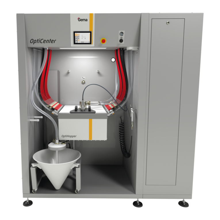
8 Automatic guns
Typical characteristics
–Powder coating in 2 operating modes
–Cleaning in cleaning mode
–User administration and language management
–Recipe management / application data management
–Configuration and parameter data management
–Alarm handling
–Diagnostic functions
–Operating data acquisition
–Control and regulation of height, length and depth detection
–Storage of operating data (e.g.: running time of guns, axes, fans) on
the SD cards
–Data exchange with higher-level plant controls (option)
–PC-based central control module for booths, gun controls, axes and
powder supply

Rev. 00 08/17
14
Product description MagicControl 4.0 (CM40)
–Large-screen 15.6” display with symbols
–TFT color screen with touch screen function
–CAN bus technology
–Multilingual version
–Installation in control cabinet or on stands
MagicControl CM40
Monitor
15.6"
SD card
1
Number of guns
55
Number of stations
10
Number of axes
24
Axis type
from ZA04
from XT09
Scope of delivery
–SD card
–Operating manual

Rev. 00 08/17
MagicControl 4.0 (CM40) Product description
15
TechnischeDaten
Technical Data
System
MagicControl CM40
Processor
ARM Cortex-A9 800 MHz
Internal memory
512 MB RAM, 1 GB SLC
Remanent memory
128 kB
Electrical data
MagicControl CM40
Nominal voltage
24 VDC SELV, extra-low safety
voltage
Voltage range
24 VDC acc. to DIN 19240
19.2 - 30.0 VDC effective
Reverse voltage protection
yes
Protection
yes (internal inaccessible melting fuse)
Electrical insulation
no
Current consumption
max. 21.6 W/24 VDC
Switch-on current max.
1 A2s
Dimensions
MagicControl CM40
Mechanical dimensions
404 x 255 x 76 mm
Window
388 x 239 mm
Display
MagicControl CM40
Technology
Projected Capacitive Touch (PCT)
Screen diagonal
15.6"
Resolution
1366 x 768 pixels (WXGA)
Number of colors
≈ 16.7 million (color depth 24 Bit)
Display surface
344 x 194 mm
Operation
Multifinger touch
Front screen
anti reflex coated, scratch-proof

Rev. 00 08/17
16
Product description MagicControl 4.0 (CM40)
Connections
MagicControl CM40
Ethernet 1
RJ-45 socket, 8-pin, 2 LEDs
(CAT5e/6), LAN1, 10/100 Mbps
Ethernet 2
RJ-45 socket, 8-pin, 2 LEDs
(CAT5e/6), LAN1, 10/100 Mbps
USB host
USB 2.0, not galvanically isolated,
plug type A, full power (500 mA)
USB device
USB 2.0, not galvanically isolated,
plug type B
COM1
RS-232, not galvanically isolated,
SUB-D connector 9-pin
COM2
RS-485, not galvanically isolated,
SUB-D connector 9-pin
CAN
CAN1, not galvanically isolated, SUB-
D connector 9-pin
SD card slot
SDSC or SDHC according to SDA
specification 2.0
Environmental conditions
MagicControl CM40
Climate
0-50 °C, 10-95% relative humidity, not
condensing
Vibration / shock / drop test
Vibration –IEC 60068-2-6
Shock –IEC 60068-2-27
Drop test –IEC 60068-2-31
Rating plate
A rating place is attached to the back of the device for the purpose of
identification. The rating place contains the following information:
–Type designation
–Version
–Required power supply
–Serial no.
–Arrangement of interfaces and operating elements
Fig.
3
: Rating plate

Rev. 00 08/17
MagicControl 4.0 (CM40) Product description
17
Design and function
Operating and display elements
Fig.
4
: Front and back
Designation
Description
1
Display, touch
sensor
Operating and display elements
Acquisition of the actuation of the
operating elements shown on the display.
Operated by touch using fingers.
2
SD card slot
Slot for SD card
3
CTRL button
Exits the visualization program

Rev. 00 08/17
18
Product description MagicControl 4.0 (CM40)
Connections and interfaces
Fig.
5
: Connections
Connection
Description
1
Ethernet 1
RJ-45 socket, 8-pin, 2 LEDs (CAT5e/6),
LAN1, 10/100 Mbps
2
Ethernet 2
RJ-45 socket, 8-pin, 2 LEDs (CAT5e/6),
LAN1, 10/100 Mbps
3
USB host
USB 2.0, not galvanically isolated, plug
type A, full power (500 mA)
4
USB device
USB 2.0, not galvanically isolated, plug
type B
5
COM1
RS-232, not galvanically isolated, SUB-D
connector 9-pin
6
COM2
RS-485, not galvanically isolated, SUB-D
connector 9-pin
7
CAN
CAN1, not galvanically isolated, SUB-D
connector 9-pin
8
Power supply
MSTB plug connector, 3-pin
9
SD card slot
SDSC or SDHC according to SDA
specification 2.0

Rev. 00 08/17
MagicControl 4.0 (CM40) Product description
19
Symbols
Fig.
6
Navigation bar
Plant overview
Information bar
-
Mode-dependent bar
Login status bar
Function keys
The function keys are distributed on the user interface.
Automatic operation
mode
Cleaning operation
mode
Manual operation mode
Main menu
Plant - OFF
(Press and hold 2
seconds)
Cyclone
Powder management
Filter ON/OFF or
High/Low frequency
Guns ON/OFF ﴾=
powder﴿
Squeegee ON/OFF
Floor blow-off ON/OFF
Guns‐External cleaning
ON/OFF
Axes move to reference
position
Axes ON/OFF
Safety grid (access
release ON/OFF)
Reference axes
Start/Cancel

Rev. 00 08/17
20
Product description MagicControl 4.0 (CM40)
Intermediate rinsing
ON/OFF
Gun rinsing ON/OFF
Vibrator ON/OFF
Meaning of the colors
System components
Background color Grey
= present, but not active
Border color Orange
= active state
e.g. fan running, powder management system is ready
Border color Red
= Error
Guns and axes
black/grey
= present, but not active
orange
= active state
e.g. gun sprays powder, axis running
red
= Error
Other manuals for MagicControl 4.0
1
Table of contents
Other Gema Control Unit manuals
Popular Control Unit manuals by other brands

Bosch
Bosch FLM-420-NAC-D installation guide

AKO
AKO V Series operating manual

Honeywell
Honeywell Esser 8044 Series Installation instruction

Miele
Miele XKS 3130 W Fitting and installation instructions

Roger Technology
Roger Technology H70/101AC Instructions and Recomendations for the Installer

Exhausto
Exhausto EBC 10-P Installation & operating manual