HB935/A /B /C /D
TECHNICAL INFORMATION
To replace the hinge housing assy:
- Undo the screws of the main grip.
- Take the main grip off stand.
- Remove the black plastic tube from the column.
- Slide the lamp housing together with the slider off the
column.
To replace the paw and the paw cap (L&R) and the wheels:
- Undo the screw on the inside of the paw.
- Unsnap the paw caps.
- The wheels are now accessible.
- Undo 4 screws in the point of rotation of the paw to detach
the paw.
To replace the sliding plug leg:
- To replace the sliding plug of the leg, the existing sliding
plug has to be smashed with the pointed end of a hammer;
otherwise it can’t be removed without damaging the leg. A
new sliding plug can simply be snapped onto the leg.
6. Resetting the timer and hour counter
- When the timer has detected a “temporary” fault, it shows
an error code on the display.
- If the error code does not disappear, there is probably a
defect in the relay board or the checking device in the
software.
- Reset the hour counter (e.g. after replacing the UV lamps).
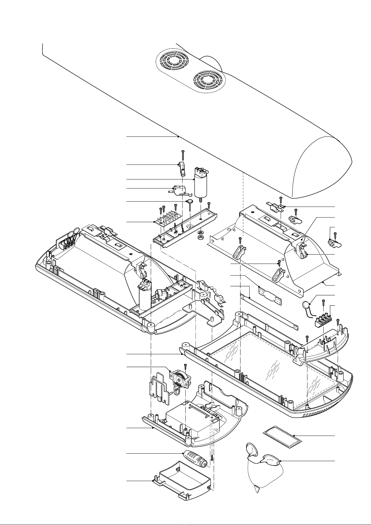
Always unplug the appliance before disassembly or repair!
1. Replacing lamps, fans and starters.
- Fold the appliance out into operating position.
- Remove 12 screws on the bottom of the lamp housing.
- Remove the upper part of the lamp housing
(the fans, starters and internal wiring are now accessible)
- Remove the screws of the mounting bridge.
- Remove the reflector clamps.
- Remove the reflector.
You have to lift the mounting bridge to do so.
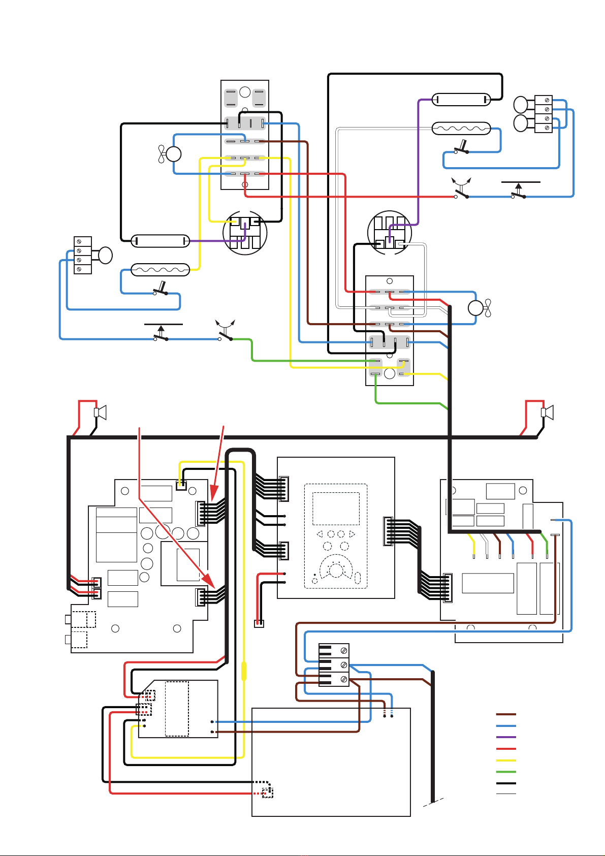
2. Replacing lock grips, soundboard, relay board and power
SMPS (PCB)
- Remove the back of the timer housing.
- Now the lock grips, sound board, relay board and the power
SMPS are accessible
3. Replacing timer front with speakers and display
- Remove the grip main assy and slide the lamp housing
together with the slider off the column and place it on a table
or bed with the front pointing downwards.
- Remove the back of the timer housing.
- Remove the sound board, the relay board and the power
SMPS and undo the plug-in connections.
- Undo the 4 screws attaching the front to the black sleeve.
- Now the front can be removed.
4. Replacing seesaws (always replace both)
- Start disassembling the appliance as described under 3.
- Remove the back of the timer housing.
- Remove the 4 screws attaching the front to the black sleeve.
- Remove the black sleeve.
- Remove 2 shafts.
- Remove the spring. Be careful, for the spring is tensioned.
- Remove the seesaws.
5. Stand
- The column of the stand has been mounted by means of
a hydraulic press and cannot be removed without causing
serious damage.
- As a result, the hinge housing cannot be disassembled either.
- The legs have been mounted on the paw by means of a
hydraulic press and cannot be removed without causing
serious damage.
DISASSEMBLY & REPAIR INSTRUCTION
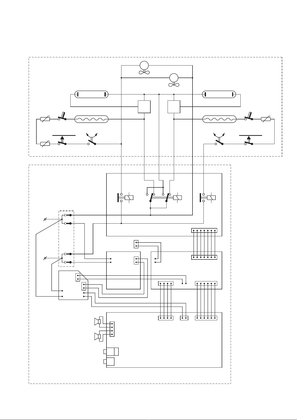
- Input voltage : 230 V – 50 Hz.
- Input consumption : Approx. 2200 W
- Fuse : 16 A
- UVA source : 2 x Philips Cleo HPA SYNERGIE
- IR source : 2 x Philips type 15040R
- Starter : KAIDA KCCD-G400
- Timer : 45 min. (Digital)
- Radiation area : 190 x 70 cm
- Output (min) : 0.2 W/cm² at 65 cm. straight
UVX-36 meter below the distance indicator
- Protecting goggles : 2 x HB072
- Safety : Class II Cenelec UV type 3
- Weight : Approx. 19 kg.
+ 1x + 2x+ 1x
1
01 234567
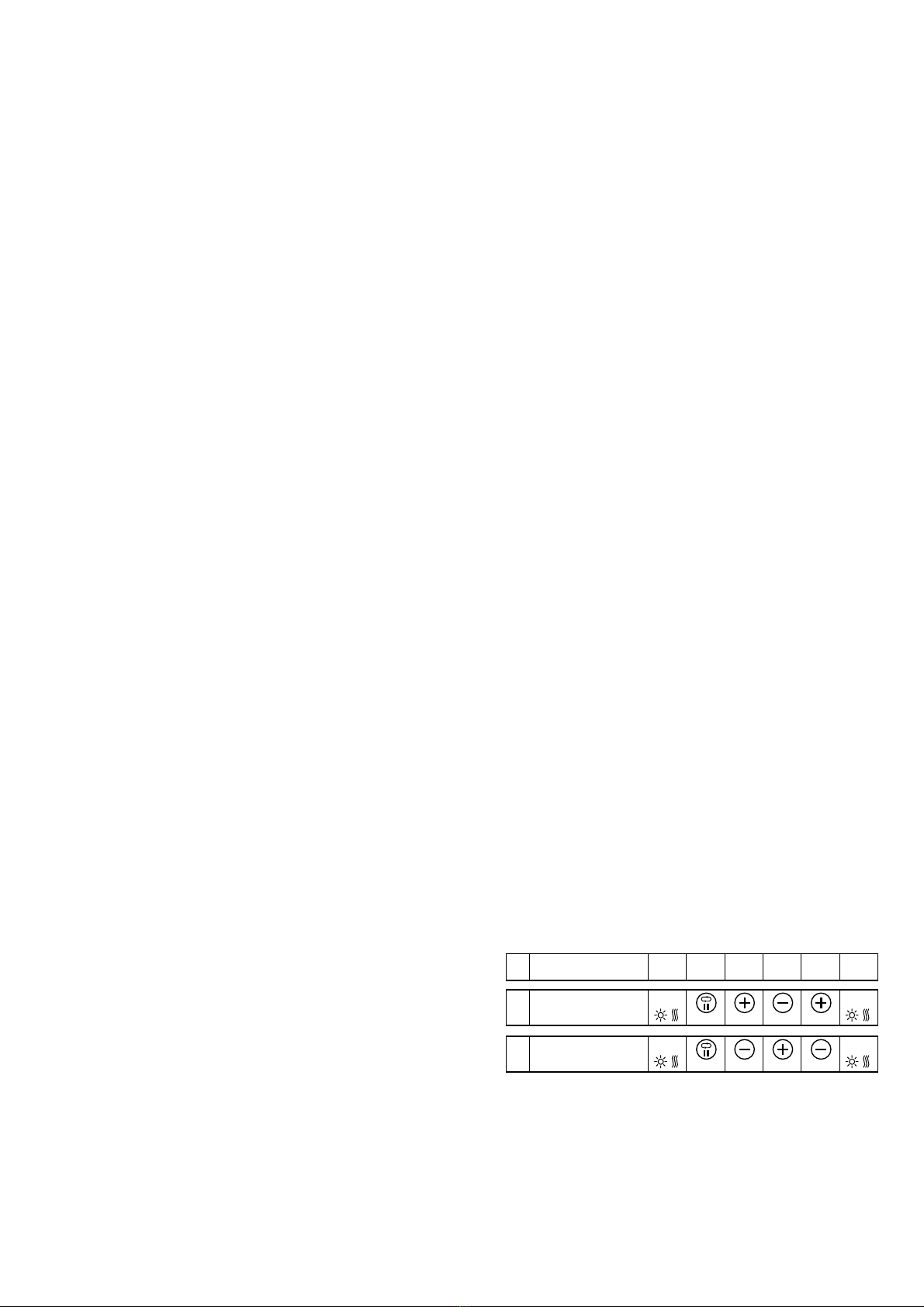
Resetting
the timer
Resetting
the hour counter
Press
00 00
+ 2x + 1x+ 1x
1Press
00 00
2-12