2
GB | Digital Clamp Multimeter
Before you begin using the multimeter, read this instruction manual
thoroughly. It contains particularly important passages concerning
occupational safety principles when using the device. Such passages are
highlighted. Reading the manual will prevent potential injury by electric
current or damage to the device.The clamp multimeter was designed in
accordance with the IEC-61010 standard regarding electronic measuring
devices in the category (CAT III 600 V), 2nd pollution degree.
Category CAT III is designed for measuring circuits powered by a xed
output power supply, such as relays, sockets, switchboards, power
supplies, short branching circuits and lighting systems in large buildings.
Electrical Symbols
alternating current (AC)
direct current (DC)
direct and alternating current (AC/DC)
warning – read the manual before use
risk of injury by electric shock
earthing
declaration of conformity (CE)
the device is protected by double insulation and thickened insula-
tion
ATTENTION
Comply with the following instructions in particular:
This device is not intended for use by persons (including children) whose
physical, sensory or mental disability or lack of experience and knowledge
prevents safe use, unless they are supervised or instructed regarding use
of the appliance by a person responsible for their safety. It is necessary to
supervise children to ensure they do not play with the device.
• Make sure the device is not damaged before you begin using the
multimeter. If you nd obvious signs of damage on the device, do not
make any measurements! Check that the surface of the multimeter
does not have scratches and that the side joints are not coming apart.
• Check the insulation on the measuring probes. Damaged insulation
may result in injury by electric current. Do not use damaged meas-
uring probes or jaws!
• Do not measure voltage higher than 600 V, or current higher than
400 A!
• The COM terminal must always be connected to reference ground.
• If you nd that the multimeter is making abnormal measurements,
stop using it. If you are unsure of the cause of the defect, contact
a service centre.
• Do not measure voltages and currents higher than indicated on the
front panel of the multimeter and the jaws. Risk of injury by electric
current or damage to the multimeter!
• Check that the multimeter is working properly before use.Test on a
circuit with known electrical values.
• Before you connect the multimeter to a circuit you intend to measure,
turn o the power to the circuit.
• Do not use or store the multimeter in environments with high
temperature, dust or humidity. It is also not recommended to use
the device in environments with potentially strong magnetic elds
or risk of explosion or re.
• When replacing batteries or other parts of the multimeter, use spare
parts of the same type and specications. Replace only when the
multimeter is turned o and disconnected!
• Do not alter or otherwise interfere with the internal circuitry of
the multimeter!
• Be extra careful when measuring voltages higher than 30 V AC rms,
42 V peak or 60 V DC. Risk of injury by electric current!
• When handing measuring tips, make sure you are holding them
behind the nger barrier.
• To prevent electric shock, do not touch any bare conductors with
hand or skin.
• Disconnect the measuring tips from the tested circuit before opening
the casing of the multimeter.
• Do not perform measurements if the multimeter’s casing is removed
or loose.
• Once the screen shows the low battery icon„ “, replace the bat-
teries. Otherwise, subsequent measurements may be inaccurate. In-
correct measurements may then result in injuries by electric current!
WARNING
Use the MD-410C multimeter only in the manner specied below. Other
uses may cause damage to the device or injury to your health. Comply
with the following instructions:
• Before measuring resistance, diodes or current, disconnect the
circuits from the power supply and discharge the high-voltage
capacitors.
• Before measuring, make sure the circular switch for measuring
range is in the correct position. Do not under any circumstances
make any changes to the measuring range (by moving the circular
switch for measuring programmes) while measuring! Doing so could
damage the device.
• If you intend to measure current, turn o the power supply to the
circuit before you connect the multimeter.
Device Description
Clamp multimeter MD-410C belongs to a series of compact devices with
3 3/4 digit display that are designed to measure direct and alternating
voltage, direct and alternating current, resistance, temperature, test
diodes and perform audio testing of conductivity and of circuits. The
multimeter is tted with automatic range adjustment for measuring
values. It indicates the exceeding of the measuring range. It features an
automatic switch-o function.
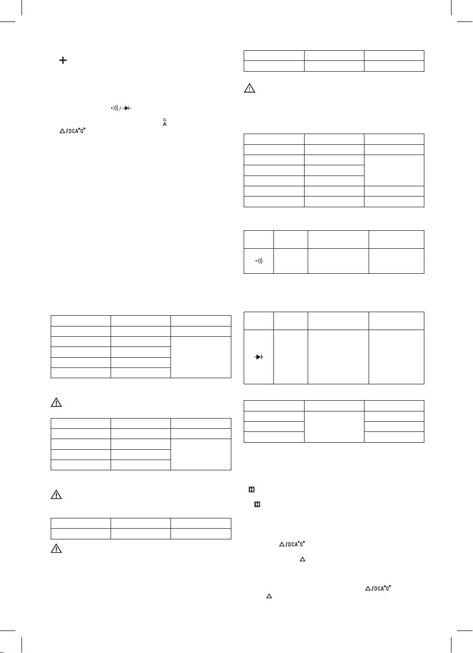
Specications
Screen: LCD, 3999 (3 3/4 digits) with automatic polarity indication
Measuring method: dual-slope integration via an A/D converter
Reading frequency: 3× per second
Jaw spread: 33 mm
Max. measurable conductor: Ø 28 mm
Operating temperature and humidity: 0°C to 40°C,
relative humidity <75 %
Storage temperature and humidity: -10°C to 50°C,
relative humidity <85 %
Power supply: 2× 1.5 V AAA
Low battery: indication via battery symbol on the screen
Indication of exceeded range: shows“OL”on the LCD
Measuring category: CAT III (600 V)
Dimensions and weight: 38 × 71 × 194 mm; 211 g (including batteries)
ACCESSORIES
Manual: 1 pc
Testing conductors: 1 pair
Type K thermocouple: 1 pc
FrontView of the Multimeter
1 – Lever
Used to open and close the jaws.
2 – Turn switch
Used to select functions and to turn the meter on or o.
When the meter is not being used, turn the switch to the OFF position.
3 – Screen
3-3/4 digit LCD screen with max. reading of 3999.
1