2Tableofcontents
1 Description .............................................................................................................................. 1
2 Table of contents ..................................................................................................................... 2
3 Ordering data .......................................................................................................................... 3
4 Technical data ......................................................................................................................... 4
5 Safety and installation notes..................................................................................................12
6 High-voltage test (HIPOT) ..................................................................................................... 13
6.1 High-voltage dielectric test (dielectric strength test).................................................................... 13
6.2 High-voltage dielectric test during the manufacturing process ....................................................... 13
6.3 High-voltage dielectric test performed by the customer ............................................................... 13
7 Structure of the power supply ................................................................................................ 15
7.1 Function elements ............................................................................................................. 15
7.2 Device dimensions............................................................................................................. 15
7.3 Keep-out areas ................................................................................................................. 16
7.4 Block diagram................................................................................................................... 17
8 Mounting/removing the power supply.................................................................................... 18
8.1 Mounting the power supply unit ............................................................................................. 18
8.2 Removing the power supply unit............................................................................................ 18
8.3 Fix connection wiring to the power supply ................................................................................ 19
9 Device connection terminal blocks ........................................................................................ 20
9.1 Input............................................................................................................................... 20
9.2 Protection of the primary side ............................................................................................... 20
9.3 Output ............................................................................................................................ 21
9.4 Protection of the secondary side............................................................................................ 21
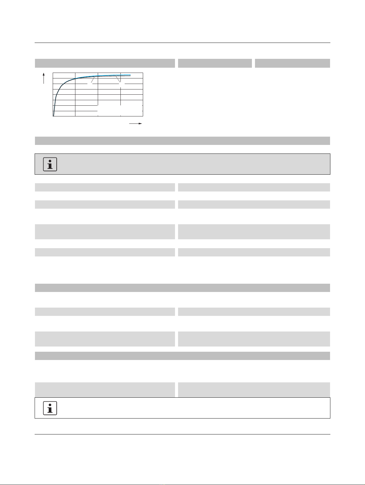
10 Output characteristic curves ..................................................................................................22
11 Boost currents ....................................................................................................................... 23
11.1 Static Boost...................................................................................................................... 23
11.2 Dynamic Boost.................................................................................................................. 23
12 Signaling................................................................................................................................ 24
12.1 Rotary selector switch in position DCOK................................................................................. 24
12.2 Rotary selector switch in position >50%, >75% or boost >100%.................................................. 24
12.3 Location and function of the signaling elements......................................................................... 24
12.4 Active signal outputs, digital ................................................................................................. 25
13 Operating modes................................................................................................................... 26
13.1 Series operation ................................................................................................................ 26
13.2 Parallel operation............................................................................................................... 26
14 Derating................................................................................................................................. 28
14.1 Ambient temperature .......................................................................................................... 28
14.2 Installation height............................................................................................................... 28