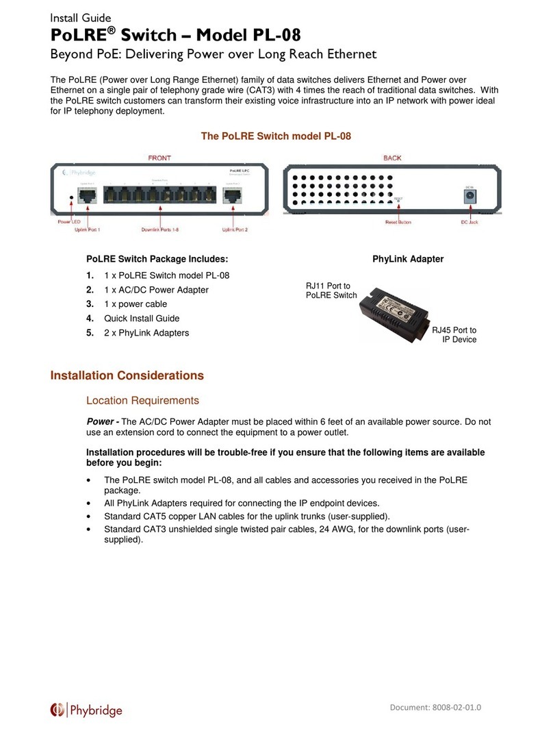
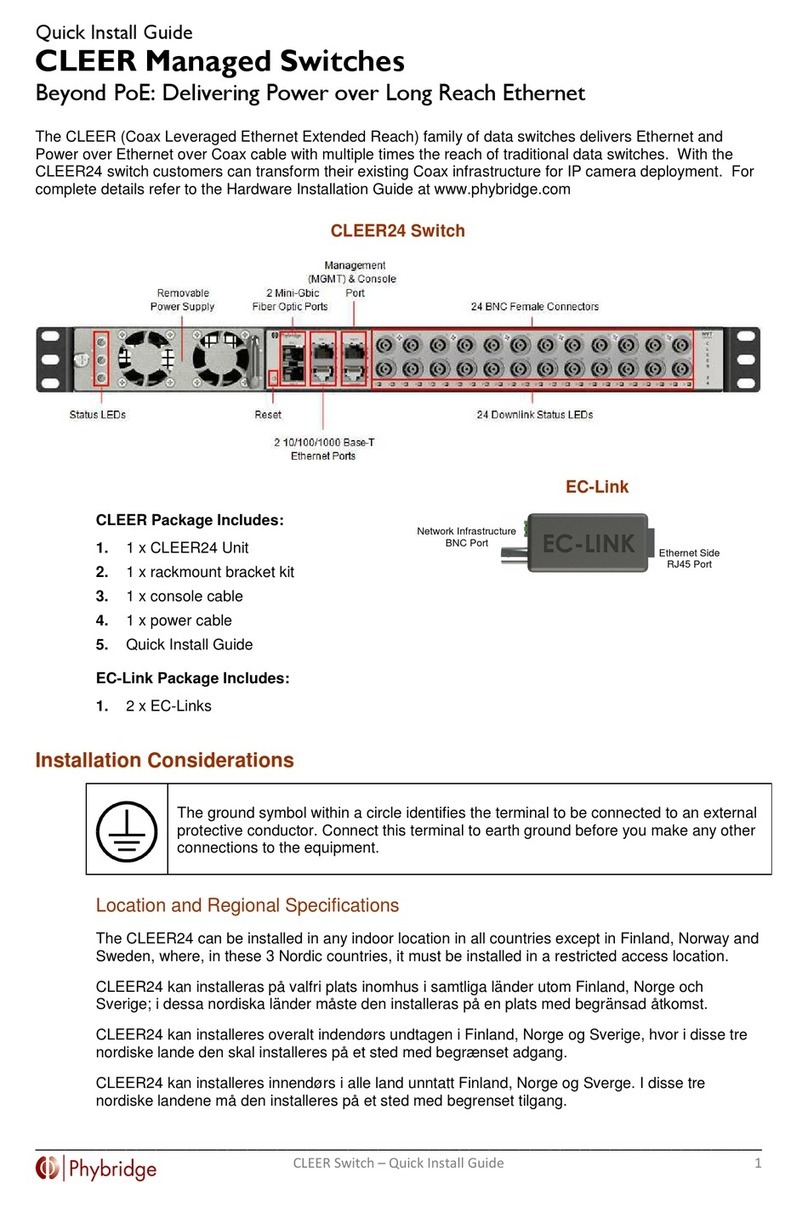
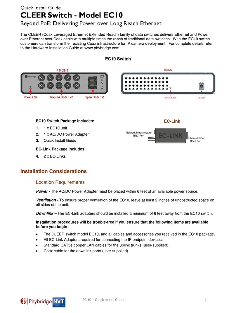
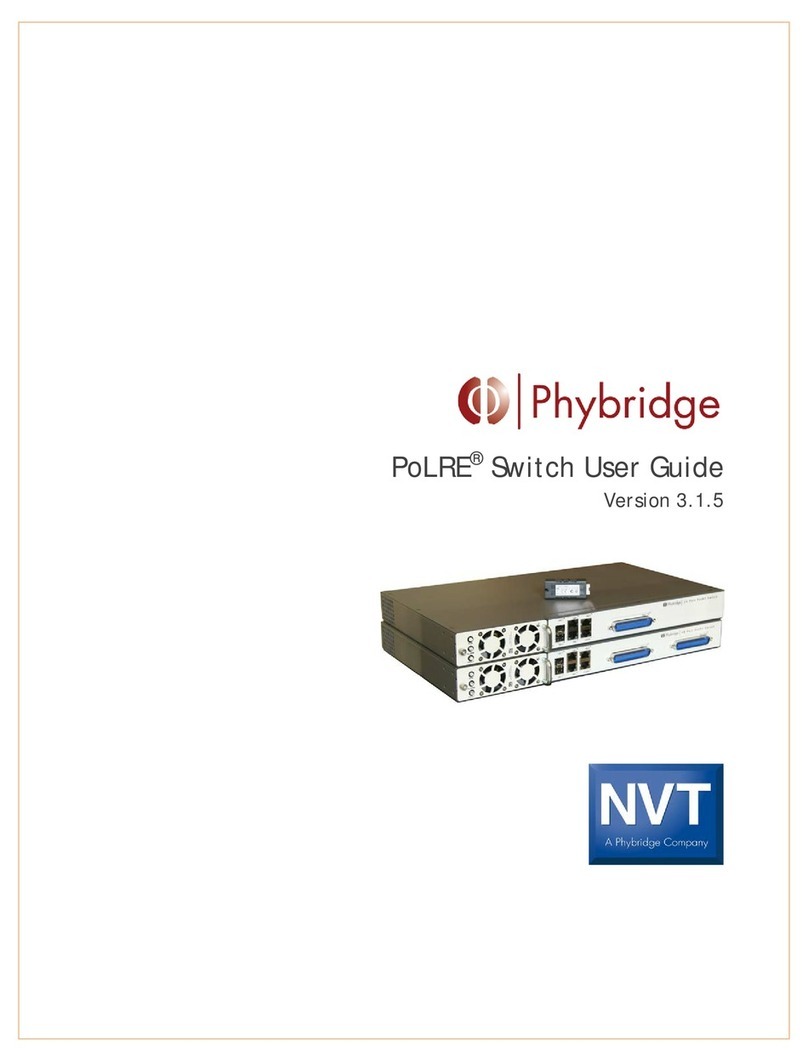
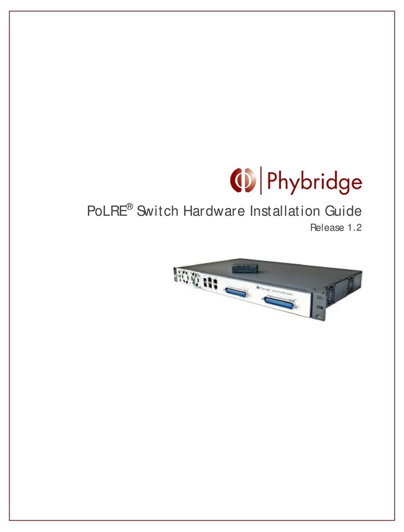
Phybridge CLEER 24 User manual

CLEER®24 Switch User Guide
Version 3.3.0

Copyright © 2014 Phybridge Inc. All Rights Reserved.
CLEER24 is a registered trademark of Phybridge Inc.
Chrome is a trademark of Google Inc.
Firefox is a registered trademark of Mozilla Inc.
Phybridge Inc. Corporate Headquarters
2115 South Service Road West
Oakville, ON
L6L 5W2, Canada
Tel: 1.888.901.3633
Fax: 1.866.252.9148

C O N T E N T S
i
P h y b r i d g e C L E E R Swi t c h U s e r G u i d e
Contents
1. Overview......................................................................................................1
About this Guide .......................................................................................................... 1
About the Simple Network Manager.................................................................................... 1
Browser Requirements ................................................................................................... 2
Software Version.......................................................................................................... 2
Logging into the Switch .................................................................................................. 2
Managing Multiple Switches ............................................................................................. 2
2. System Page ..................................................................................................3
About the System Page .................................................................................................. 3
System > Overview ....................................................................................................... 3
System Overview ...................................................................................................... 4
Ethernet Port Status .................................................................................................. 5
Viewing port status ................................................................................................ 5
Controlling power to downlink ports ............................................................................ 6
System > Performance ................................................................................................... 7
CPU Load................................................................................................................ 8
Memory (Megabytes) .................................................................................................. 8
Power (Watts).......................................................................................................... 9
Temperature (Celsius) ................................................................................................ 9
System> Log ............................................................................................................. 10
Selecting the number of events to display....................................................................... 10
Searching Log entries ............................................................................................... 10
Adding markers to the log .......................................................................................... 11
Downloading the log file............................................................................................ 11
3. Ethernet Page.............................................................................................. 13
About the Ethernet Page .............................................................................................. 13
Ethernet > Uplink Ports ................................................................................................ 13
Configure GbE Interface ............................................................................................ 15
Configure Management Port ....................................................................................... 15
Configure IP Route .................................................................................................. 16
Viewing Uplink Statistics ........................................................................................... 16
Ethernet > Downlink Ports............................................................................................. 17
Ports 1-24............................................................................................................. 17
Viewing adapter information ................................................................................... 17
Viewing port information........................................................................................ 18
Downloading the MAC address table ........................................................................... 19
4. VLAN Page .................................................................................................. 21
About the VLAN Page................................................................................................... 21
VLAN > VLAN Table ..................................................................................................... 21
Adding a VLAN ....................................................................................................... 22
Editing a VLAN ....................................................................................................... 22
Setting the default VLAN ........................................................................................... 23
Deleting VLANs....................................................................................................... 23
VLAN > VLAN To Port ................................................................................................... 23
Viewing VLAN port details.......................................................................................... 24
Assigning ports to a VLAN........................................................................................... 24
Removing ports from a VLAN....................................................................................... 24
Refreshing VLAN information ...................................................................................... 24

ii
C O N T E N T S
P h y b r i d g e C L E E R S w i t c h U s e r G u i d e
VLAN > Assign PVID ..................................................................................................... 24
PVID Table ............................................................................................................ 25
Viewing port PVID details for a VLAN ............................................................................. 25
Adding or modifying a port PVID................................................................................... 25
Refreshing VLAN information ...................................................................................... 26
5. Admin Page ................................................................................................. 27
About the Admin Page ................................................................................................. 27
Admin > Setup........................................................................................................... 27
System Settings ...................................................................................................... 28
Import/Export Configuration....................................................................................... 29
View the switch configuration.................................................................................. 29
Export configuration from the switch ......................................................................... 29
Import configuration to the switch ............................................................................ 29
Firmware Update .................................................................................................... 29
Installing a new package ........................................................................................ 30
Rebooting the system ............................................................................................... 30
Admin > Services........................................................................................................ 31
Services ............................................................................................................... 31
Remote Log Server .................................................................................................. 32
Network Time Protocol ............................................................................................. 32
Spanning Tree Protocol ............................................................................................. 32
Simple Network Management Protocol ........................................................................... 33
Admin > Terminal ....................................................................................................... 34
Using the Command Line Interface ............................................................................... 34
Adding notes to the switch......................................................................................... 35
6. Command Line Interface ................................................................................ 37
Command Reference ................................................................................................... 37
Upgrade Procedure ..................................................................................................... 44
Displaying the current installed version .......................................................................... 45
Incremental upgrade ................................................................................................ 45
Upgrade recovery and full version install ........................................................................ 46
7. Troubleshooting ........................................................................................... 47

1 . O V E R V I E W
A b o u t t h i s G u i d e
1
P h y b r i d g e C L E E R S w i t c h U s e r G u i d e
1. Ov er view
About this Guide
This user guide provides instructions to manage, control and monitor the switch using the Simple Network
Manager.
This guide is intended for operating personnel (sometimes called craft persons). Users must be familiar
with the basic operations of a Layer 2 switch. Access to the hardware interface is by a computer with a
telnet terminal.
About the Simple Network Manager
The Simple Network Manager provides you with a simple and intuitive tool to manage, control and
monitor the switch. Most operations can be performed with a click of the mouse. The Simple Network
Manager also includes a command line interface for managing the switch.
The Simple Network Manager is divided into four main pages, arranged in order of the frequency that you
will typically access them:
System
Provides a real-time overview of the system, and allows you to control downlink ports and view
detailed log activities. See "About the System Page" on page 3.
Ethernet
Provides switch configuration and management as well as uplink and downlink port
management. See "About the Ethernet Page" on page 13.
VLAN
Allows users to view, establish and assign VLANs. See "About the VLAN Page" on page 21.
Admin
Allows users to setup, configure and manage the switch, enable services and configure the
switch using a command line interface. See "About the Admin Page" on page 27.

2
1 . O V E R V I E W
B r o w s e r R e q u i r e m e n t s
P h y b r i d g e C L E E R S w i t c h U s e r G u i d e
Browser Requirements
The Simple Network Manager supports the following web browsers:
Google Chrome™ version 21 and higher
Mozilla Firefox® version 16 and higher
Software Version
The current version of the switch software is 3.3.0.
Logging into the Switch
Access to in-band management is through the gigabit uplink ports. All switches have the same default
username and password of admin.
1. Open Google Chrome™ or Mozilla Firefox®.
2. Enter the IP address of the switch in the address bar. (The default IP address of the switch is
192.168.100.1.)
3. Enter admin as the username.
4. Enter the password (the default password is admin).
Managing Multiple Switches
When managing multiple switches through the Simple Network Manager, each switch is shown as a
separate browser window or tab. The window/tab title contains the switch hostname, allowing you to
easily identify each switch.
Each tab title is composed of:
1. Hostname of the switch
2. Currently active page on the switch.

2 . S Y S T E M P A G E
A b o u t t h e S y s t e m P a g e
3
P h y b r i d g e C L E E R S w i t c h U s e r G u i d e
2. Sy st em Page
About the System Page
The System page provides high-level switch details, allowing you to monitor the system in real-time. The
data provided on the System page is helpful to troubleshoot most issues you may encounter.
The System page contains three tabs:
Overview
Performance
Log
System > Overview

4
2 . S Y S T E M P A G E
S y s t e m > O v e r v i e w
P h y b r i d g e C L E E R S w i t c h U s e r G u i d e
System Overview
Provides an overview of the switch statistics.
Model
Model.
Product Number
Product number.
Software Version
Software version.
Serial Number
Serial number.
Uptime
System uptime. Updated in real-time.
Current Time
Current date and time according to the switch. Updated in real-time.
CPU Load
Current load on the CPU. Updated in real-time.
Memory
Current used and free memory. Updated in real-time.
Temperature
Current temperature. Updated in real-time.
Host Name
Current host name. This field can be configured in Admin > Setup (see page 27).
IP Address
Current IP address. This field can be configured in Ethernet > Uplink Ports (see
page 13).
MAC Address
Current MAC address.
Subnet Mask
Current subnet mask. This field can be configured in Ethernet > Uplink Ports (see
page 13).
Default Gateway
Current default gateway. This field can be configured in Ethernet > Uplink Ports
(see page 13).
IP Address (mgmt)
Current management port IP address. This field can be configured in Ethernet >
Uplink Ports (see page 13).
PSE Voltage
Current output voltage.
PSE Power
Current power usage. Updated in real-time.
Contact
Contact information. This field can be configured in Admin > Setup (see page 27).

2 . S Y S T E M P A G E
S y s t e m > O v e r v i e w
5
P h y b r i d g e C L E E R S w i t c h U s e r G u i d e
Ethernet Port Status
Provides the uplink and downlink port status; allows you to control power to the downlink ports.
A downlink port summary above the port boxes indicates how many adapters are available and how many
are connected to endpoints.
BNC
Port number.
Description
Description of the port for easy identification; this is configured in Ethernet > Downlink
Ports (see page 17).
Days
HH:MM:SS
Length of uptime or downtime; see "Viewing port status" below.
Mbps
Megabits per second bandwidth received from the endpoint, displayed as a real-time
moving bar graph. The whole width of the field is 100%: the number shown is the
percentage and the bar is a visual representation
LAN
Uplink ports. For a breakdown of the packets received to and sent from these ports, see
Ethernet > Uplink Ports (on page 13).
Viewing port status
Hover over a port number to view port information (link details, MAC address of the main device
and a historical link down count for the port). For a breakdown of the packet information, see
Ethernet > Downlink Ports (see page 17).
The Days field shows uptime or downtime of adapter connections: black text = uptime, gold text =
downtime. This counter is reset when the port is reset.

6
2 . S Y S T E M P A G E
S y s t e m > O v e r v i e w
P h y b r i d g e C L E E R S w i t c h U s e r G u i d e
Port status can be easily identified by the colour and shading of the port box and number.
Colour
Port Status
White box
Port is available with power; nothing is attached to the port.
Grey shaded
box
Port power has been manually disabled.
Blue shaded
box
Adapter is attached to the port; nothing is attached to the adapter.
Solid blue
box
Adapter is attached to the port; an IP device is connected to the adapter.
You can lock the port to the currently connected IP device, on the Ethernet >
Downlink Ports page (see page 17). When locked, a lock icon ( ) appears
beside the Description.
Number changes
from black to red
The port number gradually changes from black to red if there is a cable fault.
Controlling power to downlink ports
You can turn the power on or off for a port.
1. Double-click a port.
2. Click OK to confirm that you want to turn the port power on or off.

2 . S Y S T E M P A G E
S y s t e m > P e r f o r m a n c e
7
P h y b r i d g e C L E E R S w i t c h U s e r G u i d e
System > Performance
All panels provide current values and the last two minutes of historical data; values are updated in real-
time. Below each panel is the defined threshold (minimum or maximum) and date of the last indicator
reading.

8
2 . S Y S T E M P A G E
S y s t e m > P e r f o r m a n c e
P h y b r i d g e C L E E R S w i t c h U s e r G u i d e
CPU Load
Legend shows the current CPU load. This value represents the number of processes waiting in queue; in a
healthy environment, CPU load should not be consistently above 1.0.
Graph provides an overview of the historical CPU load.
Memory (Megabytes)
Legend shows the current memory usage, allowing you to visualize available memory.
Graph provides an overview of historical memory usage. A flat line with few peaks and valleys is normal in
a healthy system. If memory usage keeps increasing, this may cause system instability. If this occurs, note
the used and free values in the legend and call system support.

2 . S Y S T E M P A G E
S y s t e m > P e r f o r m a n c e
9
P h y b r i d g e C L E E R S w i t c h U s e r G u i d e
Power (Watts)
Legend shows the current total power consumption. Use the legend to identify the free power availability
and manage it accordingly.
Graph provides an overview of the historical total power consumed by the switch and all devices
connected to it. Expect variations as activities on the switch change. Peaks and valleys are normal as
devices are added and removed.
Temperature (Celsius)
Legend shows the current switch temperature.
Graph provides an overview of the historical switch temperature. A flatline with few peaks and valleys is
normal in a healthy system as long as the temperature remains below 55. If the temperature remains
above 55, observe the physical switch environment to ensure proper ventilation and cooling.

10
2 . S Y S T E M P A G E
S y s t e m > L o g
P h y b r i d g e C L E E R S w i t c h U s e r G u i d e
System> Log
Use to view the system log with real-time updates. You can also add markers to the log and download the
log file.
Selecting the number of events to display
1. In the Get last list, select the number of events to display on the Log tab. You can enter a value or
use the arrows to increase/decrease the value in increments of 10.
2. Click SUBMIT. The Log tab is updated immediately .
Searching Log entries
1. You can enter multiple search terms in the “Log entries containing” window. Search terms are case
sensitive and spaces are significant.
2. Click SEARCH. The Log tab is updated immediately.
3. Search results are shown in green text and the log entries are in black.

2 . S Y S T E M P A G E
S y s t e m > L o g
11
P h y b r i d g e C L E E R S w i t c h U s e r G u i d e
Adding markers to the log
You can add markers to mark particular points in the log. For example, you could use markers to mark the
start and end points of certain events you would like to monitor. Markers are added to the log shown on
the Log tab and also to the log stored on the remote log server.
1. Enter the marker text.
2. Click MARKER. The marker is added to the log.
Downloading the log file
Click DOWNLOAD LOG FILE to save a copy of the log file shown on the Log tab. The filename for the
exported file uses the convention <hostname>.log (example: switch.log). This allows you to easily identify
which switch the file was exported from.
NOTE
You can continue using the Simple Network Manager while the file is downloading. When the file
download is complete, the file should be shown in the bottom-left corner of your browser (Chrome) or in
the Downloads window (Firefox). Double-click the file to open it.

12
2 . S Y S T E M P A G E
S y s t e m > L o g
P h y b r i d g e C L E E R S w i t c h U s e r G u i d e

3 . E T H E R N E T P A G E
A b o u t t h e E t h e r n e t P a g e
13
P h y b r i d g e C L E E R S w i t c h U s e r G u i d e
3. Et he rnet P ag e
About the Ethernet Page
The Ethernet page allows you to monitor the health of the network, configure the switch network
interface, and manage uplink and downlink ports.
The Ethernet page contains two tabs:
Uplink Ports
Downlink Ports
Ethernet > Uplink Ports
IMPORTANT
Changes that you apply are temporary. If you do not click to save changes, any changes made on this
tab will be lost after a system reboot.

14
3 . E T H E R N E T P A G E
E t h e r n e t > U p l i n k P o r t s
P h y b r i d g e C L E E R S w i t c h U s e r G u i d e

3 . E T H E R N E T P A G E
E t h e r n e t > U p l i n k P o r t s
15
P h y b r i d g e C L E E R S w i t c h U s e r G u i d e
Configure GbE Interface
Use to configure the switch network interface.
1. Modify any of the fields (IP Address, Net Mask, Broadcast, GbE1 Medium, GbE2 Medium).
Notes:
If the IP address is changed, the new IP address will be required to log back into the box.
The management port IP address and the uplink port IP address should never be on the
same subnet. This ensures the management port can still be reached if the data LAN
experiences issues.
2. Click APPLY.
Configure Management Port
Use to configure the management port IP address.
1. Modify any of the fields (IP Address, Net Mask, Broadcast, Default PVID).

16
3 . E T H E R N E T P A G E
E t h e r n e t > U p l i n k P o r t s
P h y b r i d g e C L E E R S w i t c h U s e r G u i d e
Notes:
If the IP address is changed, the new IP address will be required to log back into the box via
the management port.
The management port IP address and the uplink port IP address should never be on the
same subnet. This ensures the management port can still be reached if the data LAN
experiences issues.
The default PVID (which is the default VLAN ID for the management port) can be changed
using the command line interface in Admin > Terminal (see page 34).
2. Click APPLY.
Configure IP Route
Use to configure the default gateway IP address and to select the interface to apply it to.
1. Modify any of the fields (Default Gateway, Interface).
Notes:
The Default Gateway can be assigned to only one interface. The interface can be either GbE
or Mgmt.
If the IP address is changed, the new IP address will be required to log back into the box via
the management port.
The management port IP address and the uplink port IP address should never be on the
same subnet. This ensures the management port can still be reached if the data LAN
experiences issues.
2. Click APPLY.
Viewing Uplink Statistics
Displays a breakdown of packets received to and transmitted from the LAN ports.
Table of contents
Other Phybridge Switch manuals