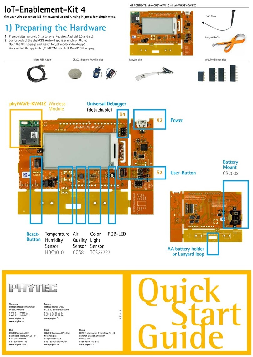
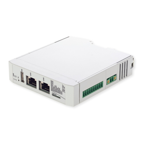
manuals.online logo
Brands
  1. Home
  2. •
  3. Brands
  4. •
  5. Phytec
  6. •
  7. Computer Hardware
  8. •
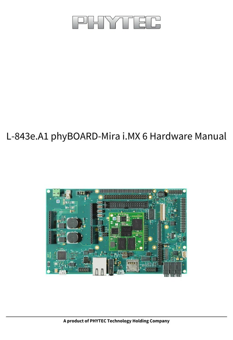
  9. Phytec L-1009e.A2 phyCORE-i.MX 8M Plus User manual

Phytec L-1009e.A2 phyCORE-i.MX 8M Plus User manual

A product of PHYTEC Technology Holding Company

L-1009e.A2 phyCORE-i.MX 8M Plus/phyBOARD-
Pollux (1549.2/1552.2) Hardware Manual






L-1009e.A2 phyCORE-i.MX 8M Plus/phyBOARD-Pollux (1549.2/1552.2) Hardware
Manual
© PHYTEC Messtecknik GmbH
2
L-1009e.A2 phyCORE-i.MX 8M Plus/phyBOARD-Pollux (1549.2/1552.2) Hardware Manual
Document Title L-1009e.A2 phyCORE-i.MX 8M Plus/phyBOARD-Pollux (1549.2/1552.2) Hardware
Manual
Article Number L-1009e.A2
Release Date 24.06.2022
SOM Prod. No. PCM-070 / PCL-070 (DSC)
SOM PCB No. 1549.2 / 1561.0 (DSC)
SBC Prod. No.: PBA-C-17
CB PCB No.: 1552.2
Edition: June 2022
L-1009e.A2 phyCORE-i.MX 8M Plus/phyBOARD-Pollux (1549.2/1552.2) Hardware
Manual
© PHYTEC Messtecknik GmbH
3
L-1009e.A2 phyCORE-i.MX 8M Plus/phyBOARD-Pollux (1549.2/1552.2) Hardware
Manual
© PHYTEC Messtecknik GmbH
4
1 Information on this Manual
This hardware manual describes the PCM-070 System on Module, referred to as phyCORE®-i.MX 8M Plus, and the
PBA-C-17, referred to as phyBOARD®-Pollux. This manual also specifies the phyCORE-i.MX 8M Plus and phyBOARD-
Pollux' design and function. Precise specifications for the NXP® Semiconductor i.MX 8M Plus microcontrollers can be
found in the i.MX 8M Plus Microcontroller Data Sheet/Reference Manual.
There will be several changes and additions to this manual. New versions will be released in the future with no
notice. Please make sure that you are using the latest version of this manual when working with your product.
1.1 Direct Solder Connection
PHYTEC produces a Direct Solder Connection (DSC) version of the phyCORE-i.MX 8M Plus SOM (PCL-070). PHYTEC
uses a Direct Solder Connection Technology (DSC) for soldering SOMs directly onto the carrier board PCB.
The “Direct Solder Connect” of the SOM to carrier board eliminates costly PCB to PCB connectors, thereby reducing
the board height. The DSC technology has an improved heat connection to the Carrier Board. It is characterized by
high mechanical strength and adheres to standard norms such as those needed for railroad applications.
Information on the DSC version of the phyCORE-i.MX 8M Plus is highlighted in bold green. Please ensure you
are using the correct information when working with your board.
1.2 Design Considerations
The schematics shown in this hardware manual are believed to be correct. However, correctness can not be
guaranteed. The schematics have been pulled from PHYTEC's designs that have been built, tested, and is known to
work. The schematics have been re-formatted to fit better in this hardware manual.
Many hardware examples and suggestions are given in the following pages. Designing the phyCORE System on
Module onto a Carrier Board is generally straightforward. However, before committing to a particular active
component selection when designing a carrier board, it is wise to check out the software driver support for those
components. A particular device may be supported in, say, for example, Linux but not in Windows Embedded
Compact 7. Your overall project may go smoother if you pick components that are already supported in your target
OS. The premade selections for our reference designs, for example our Single Board Computers, are typically
focused on using components that are well supported under Linux.
Specific details may need to be considered when designing a customer-specific carrier board. For design
information on carrier board components, please check the Design Considerations in each component section
ofphyCORE-i.MX 8M Plus on the phyBOARD-Pollux. Be aware that not all components need to be considered when
designing your own carrier board.
L-1009e.A2 phyCORE-i.MX 8M Plus/phyBOARD-Pollux (1549.2/1552.2) Hardware
Manual
© PHYTEC Messtecknik GmbH
5
1.
2.
2 Preface
As a member of PHYTEC's phyCORE® product family, the phyCORE‑i.MX 8M Plus is one of a series of PHYTEC System
on Modules (SOMs) that can be populated with different controllers, various types of memory (RAM, NAND flash,
eMMC), and many other features. This, in turn, offers increased types of functions and configurations. PHYTEC
supports a variety of 8/16/32/64-bit controllers in two ways:
As the basis for Rapid Development Kits which serve as a reference and evaluation platform
As insert-ready, fully functional phyCORE® OEM modules, which can be embedded directly into the user’s
peripheral hardware design.
Implementation of an OEM-able SOM subassembly as the "core" of your embedded design allows for increased
focus on hardware peripherals and firmware without expending resources to "reinvent" microcontroller circuitry.
Furthermore, much of the value of the phyCORE® module lies in its layout and test.
Production-ready Board Support Packages (BSPs) and Design Services for our hardware will further reduce
development time and risk and allows for increased focus on product expertise. Take advantage of PHYTEC
products to shorten time-to-market, reduce development costs, and avoid substantial design issues and risks. With
this new innovative, full-system solution, new ideas can be brought to market in the most timely and cost-efficient
manner.
For more information go to:
http://www.phytec.de/leistungen/entwicklungsunterstuetzung.html
or
http://www.phytec.eu/europe/oem-integration/evaluation-start-up.html
2.1 Ordering Information
The part numbering of the phyCORE PCM-070 has the following structure:
The part numbering for the DSC module of the phyCORE PCL-070 is following the same numbering schema.
2.2 Product Specific Information and Technical Support
In order to receive product-specific information on all future changes and updates, we recommend registering at:
http://www.phytec.de/support/registrierung.html or http://www.phytec.eu/europe/support/registration.html
L-1009e.A2 phyCORE-i.MX 8M Plus/phyBOARD-Pollux (1549.2/1552.2) Hardware
Manual
© PHYTEC Messtecknik GmbH
6
For technical support and additional information concerning your product, please visit the support section of our
website which provides product-specific information, such as errata sheets, application notes, FAQs, etc.
https://www.phytec.de/produkte/system-on-modules/phycore-imx-8m-plus/
or
https://www.phytec.com/product/phycore-i-mx-8m-plus/
2.3 Declaration of Electro Magnetic Conformity of the PHYTEC
phyCORE®‑i.MX 8M Plus
PHYTEC System on Modules are designed for installation in electrical appliances or as dedicated Evaluation Boards
(i.e.: for use as a test and prototype platform for hardware/software development) in laboratory environments.
PHYTEC products fulfill the norms of the European Union’s Directive for Electro Magnetic Conformity in accordance
with the descriptions and rules of usage indicated in this hardware manual (particularly in respect to the pin header
row connectors, power connector, and serial interface to a host-PC).
2.4 Product Change Management and Information Regarding Parts
Populated on the SOM / SBC
With the purchase of a PHYTEC SOM / SBC, you will, in addition to our hardware and software possibilities, receive
free obsolescence maintenance service for the hardware we provide.Our PCM (Product Change Management) team
of developers is continuously processing all incoming PCN's (Product Change Notifications) from vendors and
distributors concerning parts that are used in our products.Possible impacts on the functionality of our products
due to changes in functionality or obsolesce of certain parts are constantly being evaluated in order to take the
right measures either in purchasing decisions or within our hardware/software design.
Note
Assembly Options include a choice of Controller, RAM (Size/Type), Size of NAND Flash, interfaces
available, vanishing, temperature range, and other features. Please contact our sales team to get more
information on the ordering options available.

Warning
PHYTEC products lacking protective enclosures are subject to damage by ESD and, therefore, must be
unpacked, handled, or operated in environments in which sufficient precautionary measures have been
taken with respect to ESD dangers. Only appropriately trained personnel such as qualified electricians,
technicians, and engineers should handle and/or operate these products. Moreover, PHYTEC products
should not be operated without protection circuitry if connections to the product's pin header rows are
longer than 3 m.

Tip
Implementation of PHYTEC products into target devices, as well as user modifications and extensions of
PHYTEC products, is subject to renewed establishment of conformity to and certification of Electro
Magnetic Directives. Users should ensureconformity following any modifications to a product as well as
the implementation of a product into target systems.

L-1009e.A2 phyCORE-i.MX 8M Plus/phyBOARD-Pollux (1549.2/1552.2) Hardware
Manual
© PHYTEC Messtecknik GmbH
7
•
•
•
•
•
•
•
•
•
•
•
•
•
•
Our general philosophy here is: We will never discontinue a product as long as there is a demand for it.
To fulfill this, we have established a set of methods to fulfill our philosophy:
Avoidance strategies:
Avoid changes by evaluating the longevity of parts during the design-in phase.
Ensure the availability of equivalent second source parts.
Stay in close contact with part vendors to keep up with roadmap strategies.
Change management in the rare event of an obsolete and non-replaceable part:
Ensure long-term availability by stocking parts through last time buy management according to product
forecasts.
Offer long-term frame contracts to customers.
Change management in cases of functional changes:
Avoid impacts on product functionality by choosing equivalent replacement parts.
Avoid impacts on product functionality by compensating changes through hardware redesign or backward-
compatible software maintenance.
Provide early change notifications concerning functional, relevant changes to our products.
We refrain from providing detailed part-specific information within this manual, which can be subject to
continuous changes, due to part maintenance for our products.
In order to receive reliable, up-to-date, and detailed information concerning parts used for our product,
please contact our support team through the contact information given within this manual.
2.5 PHYTEC Documentation
PHYTEC will provide a variety of hardware and software documentation for all of our products. This includes any or
all of the following:
QS Guide: A short guide on how to set up and boot a phyCORE board along with brief information on
building a BSP, the device tree, and accessing peripherals.
Hardware Manual: A detailed description of the System on Module and accompanying carrier board.
Yocto Guide: A comprehensive guide for the Yocto version the phyCORE uses. This guide contains an
overview of Yocto; introducing, installing, and customizing the PHYTEC BSP; how to work with programs like
Poky and Bitbake; and much more.
BSP Manual: A manual specific to the BSP version of the phyCORE. Information such as how to build the
BSP, booting, updating software, device tree, and accessing peripherals can be found here.
Development Environment Guide: This guide shows how to work with the Virtual Machine (VM) Host
PHYTEC has developed and prepared to run various Development Environments. There are detailed step-by-
step instructions for Eclipse and Qt Creator, which are included in the VM. There are instructions for running
demo projects for these programs on a phyCORE product as well. Information on how to build a Linux host
PC yourself is also a part of this guide.
Pin Muxing Table: phyCORE SOMs have an accompanying pin table (in Excel format). This table will show
the complete default signal path, from processor to carrier board. The default device tree muxing option will
also be included. This gives a developer all the information needed in one location to make muxing changes
and design options when developing a specialized carrier board or adapting a PHYTEC phyCORE SOM to an
application.
On top of these standard manuals and guides, PHYTEC will also provide Product Change Notifications, Application
Notes, and Technical Notes. These will be done on a case-by-case basis. Most of the documentation can be found
on the applicable download page of our products.
L-1009e.A2 phyCORE-i.MX 8M Plus/phyBOARD-Pollux (1549.2/1552.2) Hardware
Manual
© PHYTEC Messtecknik GmbH
8
These manuals and more can be found in the download section of phyCORE-i.MX 8M Plus Product page.
Tip
After finishing the Quickstart Guide, we recommend working through the Development Environment
Guide. This will give you a comprehensive overview of the features and functions of both the SOM and
carrier board.

L-1009e.A2 phyCORE-i.MX 8M Plus/phyBOARD-Pollux (1549.2/1552.2) Hardware
Manual
© PHYTEC Messtecknik GmbH
9
•
•
•
•
3 Conversions, Abbreviations, and Acronyms
3.1 Conventions
The conventions used in this manual are as follows:
Signals that are preceded by an "n", "/", or “#”character (e.g.: nRD, /RD, or #RD), or that have a dash on top
of the signal name (e.g.: RD) are designated as active low signals. That is, their active state is when they are
driven low or are driving low.
A "0" indicates a logic zero or low-level signal, while a "1" represents a logic one or high-level signal.
The hex-numbers given for addresses of I2C devices always represent the 7 MSB of the address byte. The
correct value of the LSB, which depends on the desired command (read (1), or write (0)), must be added to
get the complete address byte. For example, if the given address in this manual is 0x41 =>, the complete
address byte = 0x83 to read from the device and 0x82 to write to the device
Tables that describe all settings show the default position in bold, blue text.
Tip
Due to part maintenance for our products (which are subject to continuous changes), we refrain from
providing detailed, part-specific information within this manual. Please read the sectionProduct Change
Management and Information Regarding Parts Populated on the SOM / SBCwithin the Preface for more
information.

Tip
The BSP delivered with the phyCORE-i.MX 8M Plus usually includes drivers and/or software for controlling
all components such as interfaces, memory, etc. Programming close to hardware at the register level is not
necessary in most cases. For this reason, this manual does not contain detailed descriptions of the
controller's registers or information relevant to software development. Please refer to the i.MX 8M Plus
Reference Manual, if any information not found in this manual is needed to connect customer-designed
applications.

L-1009e.A2 phyCORE-i.MX 8M Plus/phyBOARD-Pollux (1549.2/1552.2) Hardware
Manual
© PHYTEC Messtecknik GmbH
10
3.2 Types of Signals
Different types of signals are brought out at the phyCORE-Connector. The following table lists the abbreviations
used to specify the type of signal.
TABLE 1: Signal Types
Signal Type Description Abbreviation
Power In Supply voltage input PWR_I
Power Out Supply voltage output PWR_O
Ref-Voltage Reference voltage output REF_O
Input Digital input I
Output Digital output O
I/O Bidirectional input/push-pull output I/O
Input/OD-Output Input / open-drain output requires an external pull up I/OD
OC-Bidir PU Open collector input/output with pull up OC-BI-PU
OC-Output Open collector output without pull up requires an external pull up OC
OD-Bidir PU Open-drain input/output with pull up OD-BI-PU
OD-Output Open-drain output without pull up requires an external pull up OD
5 V Input PD 5 V tolerant input with pull-down 5V-PD
USB IO Differential line pairs 90Ohm USB level bidirectional input/output USB_I/O
ETHERNET Input Differential line pairs 100Ohm Ethernet level input ETH_I
ETHERNET Output Differential line pairs 100Ohm Ethernet level output ETH_O
ETHERNET IO Differential line pairs 100Ohm Ethernet level bidirectional input/output ETH_I/O
PCIe Input Differential line pairs 100Ohm PCIe level input PCIe_I
PCIe Output Differential line pairs 100Ohm PCIe level output PCIe_O
L-1009e.A2 phyCORE-i.MX 8M Plus/phyBOARD-Pollux (1549.2/1552.2) Hardware
Manual
© PHYTEC Messtecknik GmbH
11
Signal Type Description Abbreviation
PCIe IO Differential line pairs 100 Ohm PCIe level input or output PCIe_I/O
HDMI Input Differential line pairs 100 Ohm HDMI level input HDMI_I
HDMI Output Differential line pairs 100 Ohm HDMI level output HDMI_O
MIPI CSI-2 Input Differential line pairs 100Ohm MIPI CSI‑2 level input CSI2_I
MIPI DSI-2 Output Differential line pairs 100 Ohm MIPI DSI-2 level output DSI2_O
CAN FD IO Differential line pairs 120 Ohm CAN FDlevel bidirectional input/output CAN_I/O
L-1009e.A2 phyCORE-i.MX 8M Plus/phyBOARD-Pollux (1549.2/1552.2) Hardware
Manual
© PHYTEC Messtecknik GmbH
12
3.3 Abbreviations and Acronyms
Many acronyms and abbreviations are used throughout this manual. Use the following tableto navigate unfamiliar
terms used in this document.
TABLE 2: Abbreviations and Acronyms Used in this Manual
Abbreviation Definition
BGA Ball Grid Array
BSP Board Support Package (software delivered with the Development Kit including an
operating system (Windows or Linux) preinstalled on the module and development tools)
CB Carrier board; used in reference to the phyCORE development kit carrier board
DSC Direct Soldering Contact
EMI Electromagnetic Interference
GPI General-purpose input
GPIO General-purpose input and output
GPO General-purpose output
IRAM Internal RAM; the internal static RAM on the NXP® Semiconductor i.MX 8M Plus
microcontroller
J Solder jumper; these types of jumpers require solder equipment to remove and place
JP Solderless jumper; these types of jumpers can be removed and placed by hand with no
special tools
OEM Original Equipment Manufacturers
PCB Printed circuit board
PCM Product Change Management
PCN Product Change Notification
PMIC Power management IC
RTC Real-time clock
L-1009e.A2 phyCORE-i.MX 8M Plus/phyBOARD-Pollux (1549.2/1552.2) Hardware
Manual
© PHYTEC Messtecknik GmbH
13
Abbreviation Definition
SBC Single Board Computer
SMT Surface mount technology
SOM System on Module; used in reference to the PCM-070 /phyCORE®-i.MX 8M Plus module
Sx User button Sx (e.g. S1, S2, etc.) used in reference to the available user buttons, or DIP-
Switches on the carrier board
Sx_y Switch y of DIP-Switch Sx; used in reference to the DIP-Switch on the carrier board
VM Virtual Machine
L-1009e.A2 phyCORE-i.MX 8M Plus/phyBOARD-Pollux (1549.2/1552.2) Hardware
Manual
© PHYTEC Messtecknik GmbH
14
•
•
•
•
•
•
•
•
•
•
•
•
•
•
•
•
•
•
•
4 phyCORE-i.MX 8M Plus Introduction
The phyCORE‑i.MX 8M Plus belongs to PHYTEC’s phyCORE System on Module family. The phyCORE SOMs represent
the continuous development of the PHYTEC System on Module technology. Like its mini-, micro-, and nanoMODUL
predecessors, phyCORE boards integrate all core elements of a microcontroller system on a subminiature board
and are designed in a manner that ensures their easy expansion and embedding in peripheral hardware
developments.
Independent research indicates approximately 70% of all EMI (Electro-Magnetic Interference) problems are caused
by insufficient supply voltage grounding of electronic components in high-frequency environments. The phyCORE
board design features an increased pin package, which allows for the dedication of approximately 20% of all
connector pins on the phyCORE boards to Ground. This improves EMI and EMC characteristics and makes it easier
to design complex applications meeting EMI and EMC guidelines using phyCORE boards, even in high noise
environments.
phyCORE boards achieve their small size through modern SMT and multi-layer design. Due to the complexity of our
modules, 0201-packaged SMT components and laser-drilled microvias are used on the boards, providing phyCORE
users with access to this cutting-edge miniaturization technology for integration into their own design.
The phyCORE‑i.MX 8M Plus is a subminiature (40 mm x 37 mm) insert-ready System on Module populated with the
NXP® Semiconductor i.MX 8M Plus microcontroller. Its universal design enables it to be inserted into a wide range of
embedded applications. All controller signals and ports extend from the controller to high-density pitch, or surface
mount technology (SMT 1.27 mm grid) connectors (all pitch 0.5 mm) aligning two sides of the board, allowing it to
be plugged or soldered into any target application like a "big chip".
The descriptions in this manual are based on the NXP® Semiconductor i.MX 8M Plus. Descriptions of compatible
microcontroller derivative functions are not included, as such functions are not relevant for the basic functioning of
the phyCORE‑i.MX 8M Plus.
4.1 phyCORE-i.MX 8M Plus Features
The phyCORE‑i.MX 8M Plus offers the following features:
Insert-ready, sub-miniature (40 mm x 37 mm) System on Module (SOM) subassembly in low EMI design,
achieved through advanced SMD technology
Mounted using Samtec Connectors or using Direct Solder Connector (DSC)
Populated with the NXP® Semiconductor i.MX 8M Plus microcontroller (BGA548 packaging)
Up to 4 ARM-A53 cores (clock frequency up to 1.8 GHz)
Machine Learning Neuronal Processing Unit (NPU) with 2.3 TOPS
1x Cortex M7 core (800 MHz). All Cortex M7 dedicated interfaces are explicitly made available on the SOM
connector.
Tensilica Hifi4 Audio DSP (800 MHz)
3D GPU GC7000UL and 2D GPU GC520L
Neural Network Accelerator (up to 2.3TOPS)
Onboard Image Signal Processor (up to 12MP resolution/ up to 375MP/s)
Boot from different memory devices (eMMC Flash standard)
Single supply voltage of +3.3 V with onboard power management
Selectable IO voltage between 1.8 V and 3.3 V
All controller-required supplies are generated onboard using sophisticated onboard Power Management
Improved interference safety achieved through multi-layer PCB technology and dedicated ground pins
up to 8 GB[1] LPDDR4 RAM
up to 64 GB[1] onboard eMMC in the commercial temperature range (up to 32 GB for I-Temp)
up to 64 MB[1]Quad SPI Nor Flash
4kB[1]I2C EEPROM
L-1009e.A2 phyCORE-i.MX 8M Plus/phyBOARD-Pollux (1549.2/1552.2) Hardware
Manual
© PHYTEC Messtecknik GmbH
15
•
•
•
•
•
•
•
•
•
•
•
•
•
•
•
•
•
•
•
•
2x USB 3.0/2.0 Dual-Role interfaces with PHY
2x 1Gbit Ethernet interfaces with TSN support (either one of them with Ethernet transceiver on the
phyCORE-i.MX 8 M Plus enabling a direct connection to an existing Ethernet network; the second as RGMII
Signals at logic-level at the signal pins instead)
3x I2C interfaces
2x SPI interfaces
1x PCIe interface
4x UART interfaces
2x CAN-FD interfaces
4x PWM outputs
1x MIPI DSI-2 interface
1x HDMI interface
2x MIPI CSI-2 camera interfaces
1x LVDS Tx interface 2 channels x4
1x 4-bit SD-Card interface
1x 8-bit SDIO interface
2x SAI audio interfaces
1x SPDIF interface
Extreme Low Power RTC Module
4x temperature sensors to monitor the board's temperature profile
All processor interfaces available at the SOM Connector
Available for different temperature grades (see Product Temperature Grades)
[1] The maximum memory size listed as of the printing of this manual.
Please contact PHYTEC for more information about additional or new module configurations available.
L-1009e.A2 phyCORE-i.MX 8M Plus/phyBOARD-Pollux (1549.2/1552.2) Hardware
Manual
© PHYTEC Messtecknik GmbH
16
4.2 phyCORE-i.MX 8M Plus Block Diagram
FIGURE 1: phyCORE-i.MX 8M Plus Block Diagram
L-1009e.A2 phyCORE-i.MX 8M Plus/phyBOARD-Pollux (1549.2/1552.2) Hardware
Manual
© PHYTEC Messtecknik GmbH
17
4.3 phyCORE-i.MX 8M Plus Component Placement
FIGURE 2: phyCORE-i.MX 8M Plus Component Placement (Top View)
L-1009e.A2 phyCORE-i.MX 8M Plus/phyBOARD-Pollux (1549.2/1552.2) Hardware
Manual
© PHYTEC Messtecknik GmbH
18
FIGURE 3: phyCORE-i.MX 8M Plus Component Placement (Bottom View)
FIGURE 4: phyCORE-i.MX 8M Plus DSC Component Placement (Top View)
L-1009e.A2 phyCORE-i.MX 8M Plus/phyBOARD-Pollux (1549.2/1552.2) Hardware
Manual
© PHYTEC Messtecknik GmbH
19
FIGURE 5: phyCORE-i.MX 8M Plus DSC Component Placement (Bottom View)
L-1009e.A2 phyCORE-i.MX 8M Plus/phyBOARD-Pollux (1549.2/1552.2) Hardware
Manual
© PHYTEC Messtecknik GmbH
20
•
•
•
•
•
•
4.4 phyCORE-i.MX 8M Plus Minimum Operating Requirements
Before the phyCORE-i.MX 8M plus can be used, please make sure the host system meets the minimum operating
requirements. These include:
Stable and clean input power supply of 3.3 V with low ESR bulk capacitors (e.g. 2x 100µ/6.3V MLCC) paired
with some HF blocking capacitors (e.g. 100nF MLCC) connected to the input pins as near as possible
(phyCORE-i.MX 8M Plus Power Consumption)
Appropriate configuration of the I/O voltage (3.3 V or 1.8 V) configured by signal X_VIO_Ctrl (External Logic IO
Supply Voltage)
Supply voltage for externally connected peripherals should be controlled by signal X_nPWR_READY to avoid
reverse currents (External Logic IO Supply Voltage)
If external peripherals need longer reset delay, hold reset signal X_POR_B_VIO as long low as needed (Reset)
Desired boot configuration - default configuration is "Boot from onboard eMMC" (System Boot
Configuration)
To back up the onboard I2C-RTC, connect a buffer voltage source to input pin VBAT (Backup Power (VBAT /
VIN_SNVS_1V8), RTC)
Warning
We recommend connecting all available +3.3 V input pins to the power supply system on a custom carrier
board housing the phyCORE-i.MX 8M Plus and, at minimum, the matching number of GND balls
neighboring the +3.3 V balls. In addition, proper implementation of the phyCORE-i.MX 8M Plus module into
a target application also requires connecting all GND pins.
Refer to Powerfor more information.


This manual suits for next models

3

Other Phytec Computer Hardware manuals

Phytec L-820e.A2 User manual

Phytec

Phytec L-820e.A2 User manual

Phytec phyCORE-i.MX 8M Mini User manual

Phytec

Phytec phyCORE-i.MX 8M Mini User manual

Phytec phyCORE-MPC5554 User manual

Phytec

Phytec phyCORE-MPC5554 User manual

Phytec phyCORE-AM335 Series User manual

Phytec

Phytec phyCORE-AM335 Series User manual

Phytec phyCORE-i.MX 8M Mini User manual

Phytec

Phytec phyCORE-i.MX 8M Mini User manual

Phytec L-1017e.A3 i.MX 8M Plus User manual

Phytec

Phytec L-1017e.A3 i.MX 8M Plus User manual

Phytec phyCORE-TC399 User manual

Phytec

Phytec phyCORE-TC399 User manual

Phytec Cosmic-AM335 Series User manual

Phytec

Phytec Cosmic-AM335 Series User manual

Phytec L-863e.A2 phyCORE-i.MX 8M User manual

Phytec

Phytec L-863e.A2 phyCORE-i.MX 8M User manual

Phytec phyCORE-LPC3180 User manual

Phytec

Phytec phyCORE-LPC3180 User manual

Phytec phyCORE-LPC3180 Programming manual

Phytec

Phytec phyCORE-LPC3180 Programming manual

Phytec phyCORE-MPC555 Programming manual

Phytec

Phytec phyCORE-MPC555 Programming manual

Phytec phyCORE-MPC5676/57 Series User manual

Phytec

Phytec phyCORE-MPC5676/57 Series User manual

Phytec phyCORE-AM62Ax User manual

Phytec

Phytec phyCORE-AM62Ax User manual

Phytec phyCORE-DS80C390 Programming manual

Phytec

Phytec phyCORE-DS80C390 Programming manual

Phytec phyGATE Tauri-L User manual

Phytec

Phytec phyGATE Tauri-L User manual

Phytec i.MX7 PEB-D-RPI User manual

Phytec

Phytec i.MX7 PEB-D-RPI User manual

Phytec phyCORE-i.MX 8M Plus User manual

Phytec

Phytec phyCORE-i.MX 8M Plus User manual

Phytec eGrabber-4plus User manual

Phytec

Phytec eGrabber-4plus User manual

Phytec ATOM phyCORE-Z500P(T) User manual

Phytec

Phytec ATOM phyCORE-Z500P(T) User manual

Phytec L-808e.A4 User manual

Phytec

Phytec L-808e.A4 User manual

Phytec microMODUL-8051 User manual

Phytec

Phytec microMODUL-8051 User manual

Phytec phyCORE-i.MX RT1170 User manual

Phytec

Phytec phyCORE-i.MX RT1170 User manual

Phytec PhyBOARD-Mira i.MX6 User manual

Phytec

Phytec PhyBOARD-Mira i.MX6 User manual

Popular Computer Hardware manuals by other brands

MicroBT WhatsMiner M3 operating guide

MicroBT

MicroBT WhatsMiner M3 operating guide

Renesas PC7501 user manual

Renesas

Renesas PC7501 user manual

Sonnet Encore ST G4 quick start guide

Sonnet

Sonnet Encore ST G4 quick start guide

Dell OptiPlex XE4 Small Form Factor installation guide

Dell

Dell OptiPlex XE4 Small Form Factor installation guide

Ezquest Boa K16766 Specifications

Ezquest

Ezquest Boa K16766 Specifications

LSI MegaRAID SCSI 320-0X ZCR Quick installation guide

LSI

LSI MegaRAID SCSI 320-0X ZCR Quick installation guide

Alphacool GPX-A 480 M07 instruction manual

Alphacool

Alphacool GPX-A 480 M07 instruction manual

Crown IQ-P.I.P-SMT Reference manual

Crown

Crown IQ-P.I.P-SMT Reference manual

QNAP QuTS hero Turbo Station TS-1655-8G Quick installation guide

QNAP

QNAP QuTS hero Turbo Station TS-1655-8G Quick installation guide

dbx Detection and the Dynamics Duo Review guide

dbx

dbx Detection and the Dynamics Duo Review guide

VIA Technologies SOM-9X50-STK quick start guide

VIA Technologies

VIA Technologies SOM-9X50-STK quick start guide

Marvell 88MW300 Technical Product Documentation

Marvell

Marvell 88MW300 Technical Product Documentation

Exsys EX-46001 manual

Exsys

Exsys EX-46001 manual

Panasonic CZ-CBPCC2 Operation manual

Panasonic

Panasonic CZ-CBPCC2 Operation manual

schroff 23001-701 Assembly instructions

schroff

schroff 23001-701 Assembly instructions

Devon IT TC2D Quick setup guide

Devon IT

Devon IT TC2D Quick setup guide

ST X-NUCLEO-SAFEA1B How to use

ST

ST X-NUCLEO-SAFEA1B How to use

Texas Instruments SimpleLink CC3200 Wi-Fi user guide

Texas Instruments

Texas Instruments SimpleLink CC3200 Wi-Fi user guide

manuals.online logo
manuals.online logoBrands
  • About & Mission
  • Contact us
  • Privacy Policy
  • Terms and Conditions

Copyright 2025 Manuals.Online. All Rights Reserved.