USER MANUAL CL-LTPA-18RGBCEXT | 18’ COLOR CHASING LED TAPE LIGHT EXTENSION USER MANUAL CL-LTPA-18RGBCEXT | 18’ COLOR CHASING LED TAPE LIGHT EXTENSION
Please read and understand this entire manual before attempting to assemble, operate or
install the product. Please save this instruction manual.
WARNING
• Risk of electric shock: turn power o before cutting and installing.
• This tape light must be installed in a dry, open location only.
• CAUTION: To reduce the risk of re, do not install more than 2 tape lights in spaces smaller
than 12 inches by 12 inches by 12 inches.
• Use only insulated staples or plastic ties to secure power cord.
• Not intended for recessed installation in ceilings, or recessed sots.
• The National Electrical Code (NEC) does not permit cords to be concealed where damage
to insulation may go unnoticed. To prevent re danger, do not run cord behind walls,
ceilings, sots, or cabinets where it may be inaccessible for examination. Cords should be
visually examined periodically and immediately replaced when any damage is noted.
• This product is not a toy. Do not store or leave this tape light in a location accessible to
young children.
• Do not install this tape light near or in heat-producing appliances.
• Risk of re hazard, only connect a maximum of the TOTAL length.
CLLTPA18RGBCEXT LINKABLE UP TO 54’
TAPE LIGHT EXTENSION FOR CLTP16C
• Ensure NOT to exceed the above maximum total length.
PREPARATION
• Before beginning assembly, installation or operation of product, make sure all parts are
present. Compare parts with package contents list. If any part is missing or damaged, do not
attempt to assemble, install or operate the products. Contact customer service for
replacement parts.
• Tools required for assembly (not included):
• Phillips screwdriver • Safety glasses • Ladder • Scissors
IMPORTANT SAFETY INSTRUCTIONS ASSEMBLY INSTRUCTIONS
If you have questions or are missing parts, please contact customer service at 1-888-745-4837 If you have questions or are missing parts, please contact customer service at 1-888-745-4837
+24V
DO
R
GND
+24V
DI RR
1. MEASURE: Lay out the installation prior to
removing the adhesive. Ensure the mounting
surface is clean and free of any debris or
residue.
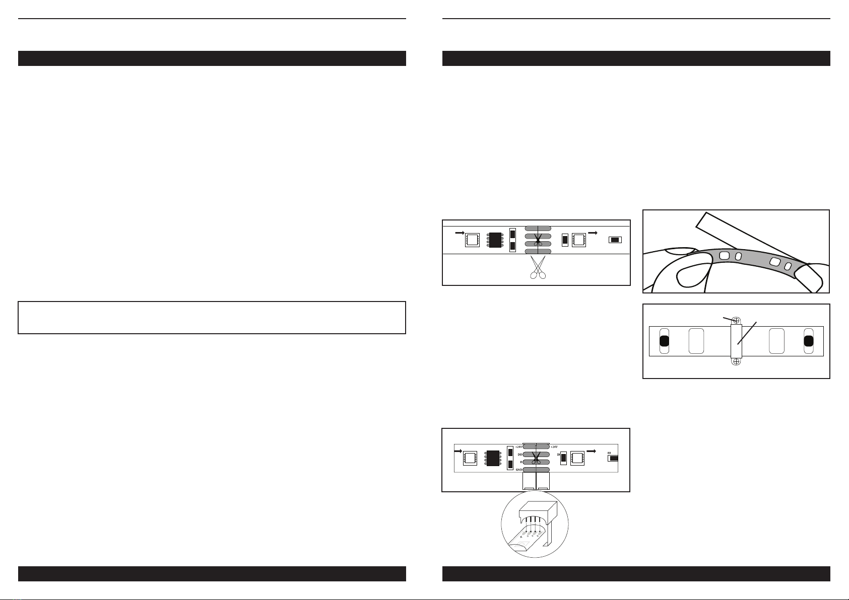
2. WHEN EXTENDING CL-TP16C: First, ensure
the power is o. Use a pair of sharp scissors
to cut the tape light (AA) at the copper pads
along the line (Fig 1). ONLY cut where the
scissor icon is showing. Cutting it in any other
area will damage the product and void the
warranty..
3. CONNECT: At each end of the cut marks,
remove a small part of the backing to expose
the adhesive tape. Open the two tabs on the
connector (BB). Insert the end of the tape
light (AA) and ensure the copper pads are
completely inserted into the connector (BB)
and that the “+”symbols align. Repeat on the
other side. Close the two tabs making sure
the metal spikes pierce through the gel side
of the tape light and secure completely.
(Fig 2).
Important Note: When connecting the
tapes, ensure the“+” signs are matching with
each other.
4. MOUNT: Remove the backing to expose
the adhesive tape (Fig 3). Place in the desired
location. To obtain optimum adhesion, ensure
the surface is clean. Rubber Mounting Clips
(CC) and Screws (DD) are also provided for
additional support (Fig 4).
Plug the power adapter that is connected to
the CL-TP16C back in to the wall socket.
Installation is now complete.
Fig 1
Fig 3
AA
AA
Fig 2
AA
AA
BB
Fig 4 CCDD AA


