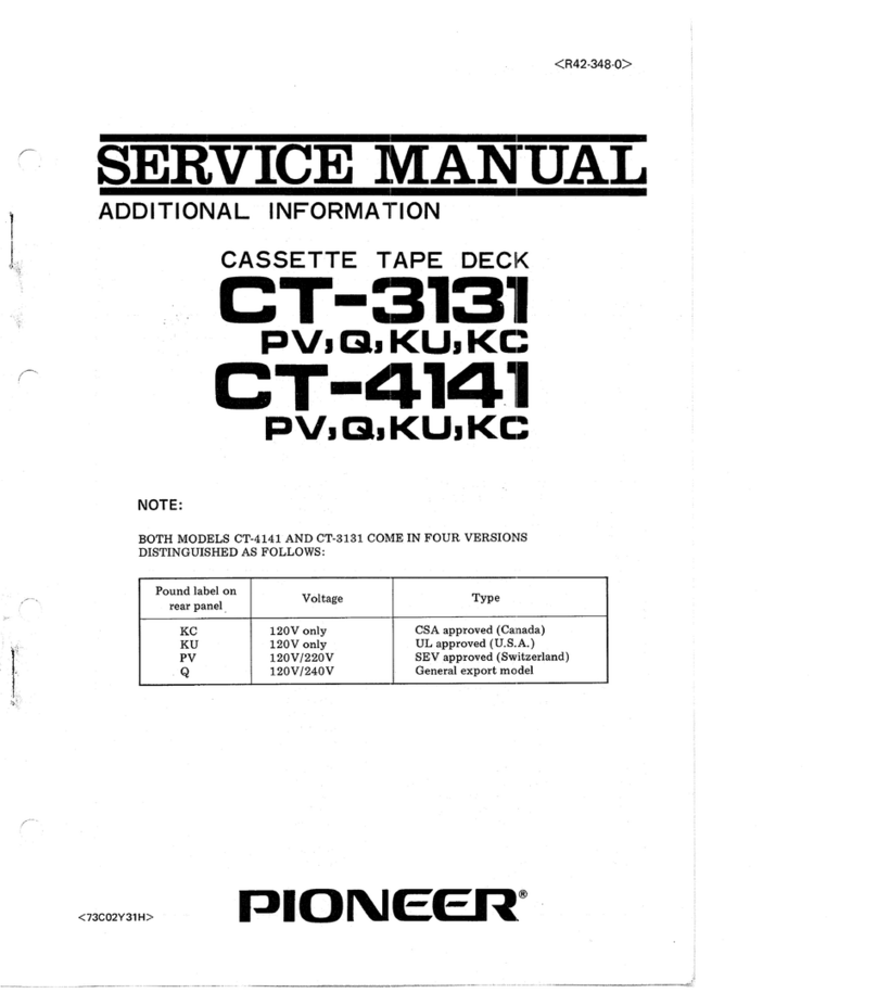
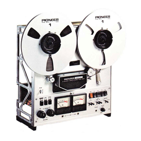
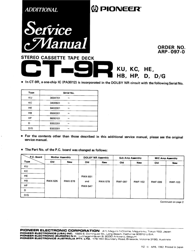
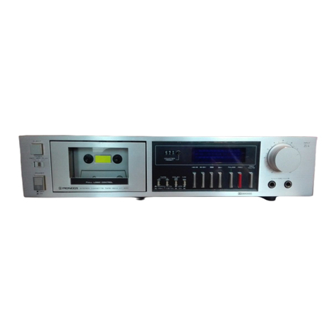
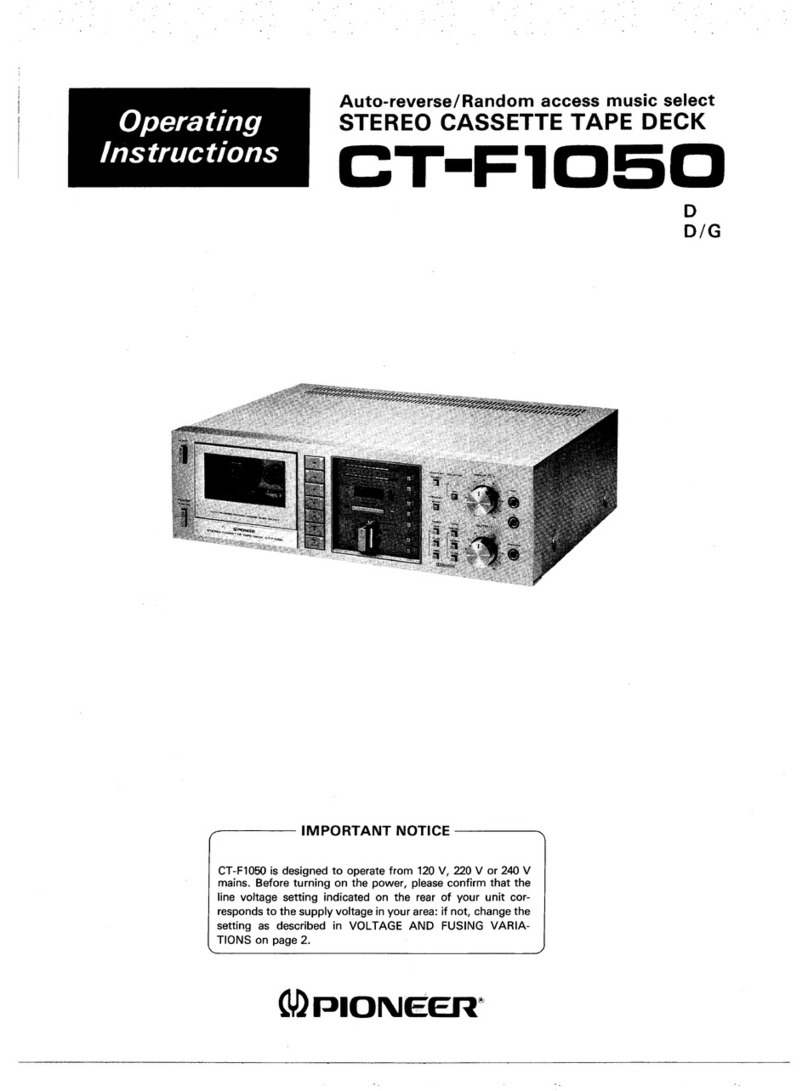
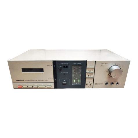
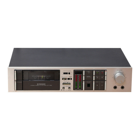
Pioneer CT-9R User manual

.Lt=tsNold(D
'pa.t
punoloJ ro I rallal aql q)tM pa\teLu st tlJftlM leutut
ral aLll ol palJauuoJ aq lsnLu uMotq punoloJ s! ttJlLlM arlM aql
'\jelq parnolal to N )alJal aql qllM pa\teLu st qstqM
leututJ, aql ol palJauuos aq )snlu anlq palnoloJ s! LIJILIMaJtM aql
s6ollo| se paaJoJd 6np rnoA ul
sleutuJJal aq) 6utAlluapt 6ur>1Leu parnoloJ aqt q)tu puodsauot 1ou
AeLu
snleJedde stqt lo peal suteu aql ut sartM aqt ]o stnolaJ eql sV
'Ajnz
le palsnfpe
Arolcel
sra6ello^Alddns
sureyl :n OtZNOIInVO
VI'IVUISNV
oNV lAOO9Nl)
OlItNn Nt3Sn
UOI
'aLutl
Jo pouad pepualxa
ue rol pasn aq ol tou s! lt uaqu tayJos ileM aq) uor] 1as
aq1 6n1du11
']Jo st gJltMS tanod aqr leqr arns illeu 'lsel palciur
uoJ ag plnoL/s ptoc nuod aqf .speal pu6rs atll 5urlcauuotsp
uaqM lddns suteut aql LuuJ luaurdtnba aq) lp lJauuoJstp s^eMM
'pLiLtostad aJr^;3s patltlenb o1 }utcrntas JaJaJ 'apsut s)Jed
alqeaJtilas )asn oN Ja^oJ a^oLual lou op ,\Jotls tulcala luataLd o1
uMo)8
;anlg :ptoc 6utuo11ol
aql qllM aJueploJJe ut palnolo3 ile peal sutetu stql ut siltil aqf
rAoo9Nr)
olltNn Ntlsn uol
a^!l
J
--INVIHOdINI---
I
o
O
o
{3il
$
g/o'o
dH,8H tj6-IC
) cro ldvr frrf ssvc olulls
peeH
lsnpues
uoqqlu
a^!rolcero -l-ld-zueno

220V,24OYmodel
SE
LECTOR
plug
Phillips
screwdriver
12OV,220V,240V
model /'a \
19 \
\16\
Y"';'
Y
Socket
L Plug
VOLTAGE
Thespecifications
of this
modeldiffer
according
to the
shipment
destination.
. For Australia
(HPstamped
on packing
case):A 2-pointvoltage
selector
switchisprovided
on the rear
panel
and
power
linevoltage
is
240V.
. For U.K. (HB stampedon packing
case):A 2-pointvoltageselector
switchis
provided
on the rear
paner
and
power
linevoltage
is
240V.
o For destinations
excluding
above
(D or D/G stampedon packing
case):A 4-pointvoltage
selectorswitch
is
provided
on the rear
panel.
NOTE:
For
thesakeof convenience,
the illustrations
andexplanations
arebasedon the
CT-gR/D.D/G.
IMPORTANT-LINE
VOLTAGE
SETTING --_-.l
CT-9R are designedto accept
different line voltages,
ac-
cording
to the country in which they areto be used,al-
though the operation
of the various
modelsis
the samein
everyrespect.Fig.
A showsthe model
designedto operate
at any of two pre-selected
voltages
(22OV
,24OVl .
Fig.
B showsthe modeldesignedto operate
at anyof three
selectedvoltages
(12OV
,22OV,24OVl.
Line
voltage
and
fuse
canbechanged
and
setasfollows:
220Vand240VMODEL
1. Disconnect
the power
cord.
2. Loosenthe screw on the selector
plug with a Phillips
screwdriver,
then
takeout the plug.
3. Re-install
the plug
with its
cutaway
section
exposing
the
correct
voltage
indication
asillustrated
(Fig.
A).
4. Tighten
themounting
screw.
12OV,22OV
and240VMODEL
1. Disconnect
the power
cord.
2. Use
a Phillips
screwdriverto take out the fuse
capand
fuse
(Fig.
B).
3. Pull
out theselector
plug
from thesocket.
4. Put the selector
plug back so that the appropriateline
voltage
markingcanbe seenthrough
thecut in theedge
of the
plug.
5. Change
thefuse
in accordance
with thetable.
6. Replace
thefuse
and
fuse
cap. B00mA

Connections
FrontPanel
Facilities
Cassette
Tape .
Playback
Recording
UsingtheTape
Deck
Functions
Using
theTape
Deckwith anAudio
Timer . . . . . 12
TapeDeckCare. ......13
DolbyNRB/CTypeSystem ......14
AutoBLEFunctions ......14
TroubleshootinS.... ....15
Specifications ....16
CONTENTS
4
6
8
10
CONNECTIONS
To avoid damaging other components, turn the power
switch
on theamplifier
OFF.
Connect the accessory
connection cables
as shown in the
f
igure.
The upper
terminals
arefor the left
channel
(L),
and
the lower
terminals
are
for theright
channel
(R).
Play back connection: Connect
the OUTPUT terminalof
the tape
deckto theTAPE PLAY terminal
of theampli-
fier.
Record connection: Connect the INPUT terminal of the
tape
deck
to theTAPE REC
terminal
of theamplifier.
NOTE:
Make certain connectors are pushed all the way in. An improper
connectton or poor contact will result in no sound. or wilt degrade
thesound.
When
connecting
the remote
control
unit JT-216
(sold
separately),
insert
the remote
control
plug
firmly in the
socket
onthe
CT
9R.
Recording
connections
to TAPE
REC
terminals
on the
amplif
ier.
AC wall socket

FRONT
PANELFACILITIES
NorE: POWER
SWTTCH
When the power switch is setto ON. the head section may be energized momentarily. However,
this is not indicative of any trouble in the unit.
C EJECT
SWITCH
Depressthis switch to open the cassettedoor.
NOTE:
When the tape is in motion (including pause) the cassette
door
will not open when thisswitch is
pressed.
@ DUALMODE
COUNTER
The counter mode selector
is used
to switch operations
from a normal
tapecounter
modeto a modethat shows
the amount of time left on the present
tape.Details
may
be
found on page
6.
NOTE:
Turning the power switch ON sets the normal tape counter
operatton.
@ COUNTER
MODE
SELECTOR
Depressthisswitchto select
thecounter
mode.
@ COUTIER
RESETSWITCH
Depressing
thisswitch
resetsthecounterto 0000.
@ LEVEL
METER
Input-output level
is shown by this indicator
during re-
cordingor playback.
G) OPERATIONSSWITCHES
* (FAST FORWARD): Depressthisswitchto fast
for-
ward the tape in the direction
from leftto right.
<< (REWIND): Depress
thisswitch
to rewind
thetapein
thedirection
from rightto left.
C:)(DIRECTION): Depressthisswitchto reversethedi-
rectionof travelof tape.
PLAY: Depressthisswitchto starttape
playback.
o STOP:Depressthisswitchto stoptapetravel.
O aLnNK
SEARcH
SWITcH
Depressing
this switch
puts
themechanism
inthe
f
astfor-
ward
mode.
When
a non-recorded
areaof over
8 seconds
durationin thefastforwardmode
isdetected,
themecha-
nismstopsthetape
and
rewinds
ittothe
proper
recording
start
position.
€) CLEAR SWITCH
Depress
this
switchto clear
thedatausedby theAUTO
BLE system.Bias
current,recording
level,
andequaliza-
tionare
setto reference
values
builtintothe
machine.
E nurO BLE
SWtTcH
Depress
this switch
to use
theAUTO BLE systemto auto-
matically
adjust
biascurrent,recording
level,
and equali-
zauon.
(E IVIUSIC
REPEAT
SWITCH
Depressing
this switch during tape playback
causes
the
songnow being
played
to be repeated.
(repeat
play
up to
eighttimes)
(TD
INDEX
SCANSWITCH
Depressing
this switch causesthe mechanism
to scanin
the directionthat the DIRECTION
switch
(CZl) is
set
to. When
a tapehasa numberof songsrecorded
on it,the
scanmechanismwill stop at the beginningof eachsong
and play about 7 seconds
of it. lf scanis
desiredduring
tape rewind, depress
this switch alongwith the rewind
switch
( << ).
@)
MS/SKtP
SWTTCH
When
this
switchis
ON,depressing
the
fast
forward
switch
(rewind
switchif traveling
inotherdirection)
causes
the
mechanism
to fastforward
to thebeginning
of thenext
song,
and restart
playback
from that point.
When the
MS/SKIP
switchison
duringnormal
playback,
blank
sec-
tions between
songsovereight
seconds
long
will be
skippedover
in the fast
forward
modeuntil the be-
ginning
of thenext
song,and
playback
willrestart
from
that
point
automatically.
)UrO ,rr, AuTO BLEis an abbreviation for Automatic BiasLevet Equalizer Tuning System. Detailsof the systemmay be found no page 14.

FRONT
PANEL
FACILITIES
@-:_-+-_->- r- TAPETRAVEL INDICATORS
t-+ l; -tl V--J Theseindicators
showthe
travel-stop
status
ot the
tape.
t: - Reverserunnrnq
MS/SK I
P INDICATO R
-----------Evs/sr'
il0co
@rrupur
KNoB
This knob is used
to adjustinput level
duringrecording.
The front knob can be turnedto adjust
the left channel,
and the backsideknob can be turned to adjustthe right
channel
independently.
@
ourpur KNoB
Thisknob isusedto adjustoutput level.
@
wrorurroR
swrrcH
Use this switch to monitor recording.
Depressing
this
switch (
^ SOURCE)allowsthe sourceto be monitored.
In this position,
the recording
sourceis
monitored
before
tape
passes
overthe recording
head.Returning
theswitch
to the TAPE ( r ) position
allowsthe tape
to be moni-
tored.Materialrecorded
on thetapeisheard
directly
after
passing
overthe recording
head.
G)AUTOTAPE
SELECT|ND|CATOR
When a cassettetape is loaded
into the unit, the sensor
holes
on the cassette
areusedto detect
the type of tape
inserted.
Biasand equalization
arethen automatically
set
according
to tapetype. This indicator
functions
to show
the
typeof tapeinuse
C) DOLBY
NR*
ON/OFF
SWITCH
Depress
this switch to usethe Dolby NR systemduring
recording
and
playback.
@ B/C
TYPESELECTOR
Depress
this switchto selectthe B type Dolby NR system
or the C type system.The indicator
on the left
will show
the
appropriateselection.
(9 NNPXFILTER
SWITCH
Depress
this
switchto recordFM stereo
broadcasts
and
TV programs
using
theDolbyNB
system.
@pause
swrrcH
Depress
this
switchto temporarily
stop
tapetravel.
This
switch
will not stoptapetravel
during
fastforward
or
duringthe rewind
mode.Depress
the switch
againto
restart
taoe
travel.
@ NCC
SWITCH
Depress
this
switchto starttaperecording.
MUSICREPEAT
INDICATOR
AUTODATA INDICATOR
This indicator blinks during the automatic adjustment
process
of AUTO BLE. When
adjustment
iscompleted
the
indicator
isilluminated.
€D
NEC
MUTE
SWITCH
Depressthis switch to create a non-recorded
section
duringtape
recording.For
details,refer
to page
10.
03 MEMORY
SWTTCH
(PUSH
ON)
Usethis switchin conjunctionwith the tapecounterand
rewind switch (in reversemode, fast forward switch)
to
automaticallV
stop tape travel at a position
set on the
counter.
Press
the switchagainto return
to normalmode
operation.For
details,
ref
erto page
1
'l
.
fq\ TAPE
CAPACITY
SELECTOR
Usethis switch to convert the counter into a remaining
tape
trmetype counter.
L46 is
usedwhena largehub
46-
minutestapeis
being
played.
€r-l
MODE
SELECTOR
SWITCH
- :At this position,
the tape
isautomatically
stopped
at
theend
of travelon either
take
up reel.
3:ln this
position,
the tapewill reverse
itsdirection
of
travelat the end of the
tapeinthe present
direction
of
travel.After the tape makes
on round trip it is
auto-
matically
stopped.
C): In this position, playback is repeatedfour complete
times.
(fourroundtrips)
?6)
TIMER
SWITCH
This switch is used
in conlunctionwith the timer for re-
cording
and
playback.
REC: Recording
automatically
commences
at the
time
seton thetimer.
OFF: Keep
in this
position
when
timernot
being
used.
PLAY: The
tapewillautomatically
be
played
back
atthe
timesetonthe
timer.
@ Mlc JACKS
(1,
R)
Plug
the microphones
into
these
jacks
when
making
mike
recordings.
€3
pnorues
JACK
Plug
the headphones
into this jackwhen monitoring
tape
recording.
or listening
to playback.
Theword "Dolby" and
!! are
trademark
of Dolby Laboratories
LicensingCorporation,
NoiseReduction
Systemmanufactured
underlicensefrom Dolby LaboratoriesLicensing
Corooration.

CASSETTE
TAPE
AUTO
TAPE
SELECTORMECHANISM
This mechanism
uses
the sensorholes
on the cassette
taoe
to detect
the type of tape
being
used.
lt then
automaticallv
adjuststhe proper recording
bias
and equalization
for the
rape.
The sensorholesfor thevarious
tape
types
are
shownin the
figure
below.
Sensor
Large
cassette
hubsand
Small
cassette
hubs
The figure showsthe differencebetweenlarge
and small
cassette
hubs. Adjust the TAPE CAPACITY SELECTOR
correctly in order to obtain an accurate
remainingtape
time.
THEDUALMODE
COUNTER
Thisunit has
adigitaltapecounter
thatcan
alsodisplay
the
amount of playbackor recording
time remaining
during
tapetransport.When
power isfirst
turnedon, the counter
operates
asa normaltapecounter.
To change
to the remain-
ingtime display,depress
the countermode
selector
switch;
a dot (.) will appearin the counter.When
the PLAY or
REC switch is depressed,
the counter will display an
approximatevalue
of the remaining
time.During
thistime,
thedot flashes
on andoff to showthecounteris
calculating
theremainingtime.
Oncecalculationshave
been
completed,
thedot will remainlit andtheexact
remaininq
timewill
be
displayed.
When tape transportis interrupted
before
the end of the
tape is reached
and then started
again,the process
starts
again,
an approximate
valuedisplayed
first and then the
exactvalue
a shorttime later.
During
the fast
forward
and
rewind modes,
the time indication
changes
in 10 second
intervals,
returning
to 1 second
intervals
when the STOP
switchisdepressed.
Whenthe direction
of tapetravel
isre-
versed,
the counter
automaticallychangesto indicate
time
remaining
inthenewdirection.
NOTE:
. Theremaining
timefunction
operates
only for tapes
with tape
capacity
selector
indicators
l4 types).
The
remainingtime
func'
tion maynot operate
properly
withcommercially
pre'recorded
tapesandtapes
with no timecapacity
markings.
6
ln this case,the AUTO BLE system will not function.
NOTE:
The tape selector /s ser to the chrome tape
position when a metal
tape without the regulated
sensing
holesisused.ln thiscase,
prop-
er recording and erasure
may not be possible. The
ptayback of pre_
recorded tapes is not affected. lt is recommended that vou use
metal tapesequipped with detection ho/es.
No sensor
holes
''3 {'i'
?)
Normal tape
Smallhubs Large
hubs
o The remaining time indication varies slightly depending on the
cassette
in use.Also, the calculator is designedto display 00.OO
while there is still a small amount of time remaininq bmount
varies
for tapelengthsand manufacturers).
. Depressing
the STOP switch while the counter is still calculat-
ing (dot is flashing on and off) may prevent the counter from
calculating the exact remaining time. Depressthe PLAY switch
againto obtain the exact value.
,ir=-*I.,
ln n r-t
nl
l,JLiUr:'l tr tr il?i:o.f'*"'
is
| . rtMr:
.F'..l,,
ln n 11 n I Durinsthe tape
lLtL|L|Lll tr tr countermode
| .rtME
.iou- r.I=.
i! 5i,l 5l tr tr ca,cu,atins
I .
rrl/E
I..,5=-o1..
IF
5.:t
Il tr l
| ____:J". Calculations com-
pl
eted
',i1{
PLAYBACK
I
H,
'In
"il
'il,
.U
I
ffi
ffi
U
D
t_
o
ol il
L l;*.-
O,
o
l=\
oo
ALWAYS
CHECKTHEFOLLOWING: lstheTIMER
switchin
theOFF
position?
When
theTIMER
switchis
ON,tapetravel
will
automatical-
lystart
when
the
POWER
switch
isturned
on.
1.
2.
Are the heads
clean?
Dirty heads
degradethe sound
quality
of theunit.
For headcleaning
procedure
refer
to TAPE DECK CARE
on page
14.
Depress
thePOWER
switch.
Loadthecassettetape.
@Witn the sideof the
tape you want to
play back facing
you andthe
exposed
tape portion down,
insert the cassette
tape in the holder.
@ctos" the cassette
o
oor.
@ Depressthe EJECT
switch
The tape indicator will be illumi-
nated according to the tYPe of
tape inserted.
3. SelecttheDOLBYNR
system.
Select
the C type DOLBY NR systemfor tapes
recorded
usingthat system.
Select
the B
type DOLBY NR svstemfor
tapesrecorded
using
that system.
4. Start playback.
STOPPING
THE TAPE TRAVEL
Depress
the
STOPswitch.
AUTO
STOP
MECHANISM
AND TRAVEL
MODE
SELECTOR
SWITCH
TheAUTO STOP
mechanism
is
setto function
according
to
the positioning
of the MODE
selector
switch.
In the
single
( - ) position,
tapetransport
stops
at the end of the side
being
played In theauto reverse
( I ) position,
tapetrans-
port is automatically
reversed
when the end of the tape is
reachedand thentape
transport
is
stopped
when
theend
of
the reverse
side
of the tape is reached.
The repeat
(
CJ )
position
automatically
reverses
tape transport
seven
ttmes
eachtime the end
of the
tapeis
reached
and
then
sropsrape
tra
n
sport.
NOTE:
. The auto-reverse
function may not operate if the cassette
tape in
use hasa cleaning-type leader tape, a leader tape with a destgn
printed on it or if there isno leader tapeat all.
. When the PAUSE switch is pressed and then released during
auto repeat, the tape will be played back another four times in
each direction.
['uI
il'
tl
o;
;ao
at o
[oil
t'
11r , -'
r"o
"-'q
na o
ofl
i1 -'
-o
Oq
no
I:9919Y NR OFF
ooLsr r a'o. ,a,r.,.
EE tr B- BorCtype
setector
TYPE
i .,.,, -,].- r
:
DOLBY NR ON

RECORDING
a
o
ALWAYS
CHECK
THE
FOLLOWING:
TIMER
switch
OFF.
Certain
sensorholes
are
provided
with thetape
being
useo.
MONITOR
switchsettoTAPE.
D
lRECTION
switchset
toforwarddirection.
Are the cassette
tape
erasure
prevention
tabs
broken off?
Cassette
tapes
cannot
be recorded
if theerasure
prevention
tabsare
broken
off.
a
O
@
1. Depress
the
POWER
switch.
2. Load
thecassette
tape.
3. Depress
theAUTO
BLE
switch.
(2)
witn the sideof the
tape you want to
play back facing
you and
the
exposed
tape portion down,
Insert the cassette
tape in the holder.
@ Ctor" the cassette
door.
lo
ll
| \-r'
"C)
O
When
AUTO BLE isnot being
used,
the referenCe
value
for
the tape
being
used
will be
adjusted
according
to theTApE
indicator position.
The CLEAR switch does not require
o
peration.
4. Place
the recording
mode into stand-by
status.
Depress
the REC
switch
andPAUSE
switch.
Approximately
five seconds
of leader
are
on the first portion of the tape.
Depress
the PLAY switch
to skip
this
portion.
5. Select
the DOLBY NR system
to beused.
I
0
o
o
E
[. ] fl
I
I]JI' L'LIL U U
_- --f'
IV
! r--- = =|!
[0_or]-
i
f'- ' ,:
U iD
tu r
flftoDo
lu fl]
H
O.n
olil
'[|,n
| ,,|l J v o
;.; o Q lir
tu
'iloo o
l) D"pr"sr
theEJECT
switch
The tape indicatorwill be illumi-
nated according to the type of
tape
inserted.
.[0..o.o
o0
o;
06
oo
I
I LlrF FirirF
r-qE Dgt-
^ lN ir,FE
: DOLBY
NR
OFF
B or C type selector
:DOI-BY
NR ON
. - _ The indicator
will
tt a! start
blink.ingstowly,
la - I
ano graduaily In-
t :.1:ur.
in frequency.
fa-- . ]When it is adjusted
-_-r
_:;"J;il"J
llll,i:
io
*- nated.
t D.pr"r,

RECORDING
6. Adjust
the
recording
level.
. Thedots (c) between +4 and +2 on the level meters
tndicate
the standard Dolby level.
NOTE:
This unit usespeak hold type meters,-peak readings are hetd for
about two secondsbefore going out.
7. Begin
recording.
AUTO
BLEOPERATION
NOTES
AUTO BLE (Auto Bias Level Equalizer
Tuning System)
uses
an internal
oscillator,
and automaticallv
records
and
plays back a portion of the tape for about an g-second
period
and
then
adjuststhe bias,
recording
level,
andequali-
zation for the particulartape being played. To assure
proper
system
operation.
observe
thenotes
and
precautions
below.
1. Always
usecassette
tape
with the proper
sensing
holes
in
the case.
(This
fact will be notedbv the AUTO TAPE
SELECTindicator)
2. The AUTO BLE system
uses
thefirst
8 seconds
of ataoe
asan operating
area
in which it records
signals
usedfor
adjustment
purposes.
Always make
certain
it is
permissi-
ble to erase
this area.
Also, if a tape is used
with the
erasure
prevention
tabs
broken
off
, AUTO BLE will not
f
unction.
3. Make certain
the MEMORY switch isin the OUT posi-
tion. lf this switch is depressed
while the AUTO BLE
function is operating
the tape may stopduring
rewind
for proper
AUTO BLE operation.
4. Make certain
the MS/SKIP switch is in the OUT oosi_
tion. lf this switch is depressed
while the AUTO BLE
function is operating
the tape may stop
during rewind
for proper
AUTO B
LE operation.
5. The AUTO BLE switch
operateseven
during
tape
trans-
port. However,
if the tape transport
mode is changed,
AUTO BLE operation
will stop
and tape
transport
will
be
changed
to thenew
mode(stop,
fast
forward,
etc.).
6. lf theAUTO DATA indicator
extinguishes
during
AUTO
BLE operations,
it is
anindication
that adjustment
is
not
possible.
lf the correct TAPE indicator
is illuminated
f
astforward
the
tapeand
attempt
ad
justment
in another
adjustment
area.lf proper
adjustment
cannot
be
obtain-
ed in this area
also,set reference
value(without usinq
AUTO
B
LE}.
Adjust so that the
highest
input levels
do not exceed
+6d8.
(Metal tape may be
setas
high
as+8dB).
Adiust
therecording
level
by monitoring
theLEVEL
IVETER.
,r1 tl
r't -'
O6
OO
The tape deck has
threeheads.
Whenthe MONITOR
switchis placed
in theTAPE
position,
thetapemaybe
monitored
immediately
afterit passes
overthe recording
head.In the SOU
RCE position,
the recording
source
may be monitored.
NOTE:
The DIRECTION switch does not operate during recording oper-
ations.
tl
':..
o
o
o
t
-t --- >_
l\ ""'-HF.Fn'r. :t
0 't
'4'l
L<-EE tJ
8. Monitoring the tape.
When the MONITOR
switch is placed in the
TAPE position,
thevolume
may be adjusted by the
OUTPUT
knob.

USING
THE
TAPEDECKFUNCTIONS
1. RECMUTESWITCH
Depressing
this switch
duringrecording
cutsout thesound
f
rom therecordedsource.Usethis
function
whilerecording
radio
broadcasts,TV programs,
etc.to cut out commercials
and other unwanted
programs.
lt isalsoconvenient
to use
while makingrecordings
f
rom recordsto cut out thetransi-
ent causedby the stylusloweringonto the record.Also,
this function isusedto create
thefour secondsnon-record-
ed sectionused
by the MUSIC REPEAT,
MS/SKIP,and
INDEX
SCAN
functionsfor
detection
purooses.
When
the portion to becut out isof longduration,
usethis
switchin conjunctionwith the PAUSE
switch.
2. MS/SKIPSWITCH
Usethis switch
to quickly locatethe beginning
of a record-
edportion
or to skip
overlong
non-recorded
portions.
Locatingthe start
of the next song
Deoressthe MS/SKIPswitchand
fastforward
switch.
When
a non-recorded
section
is detected,
playback
will start at
the beginningof the next recordingsection.
Depressthe REWINDswitch
to hear
thesong
you arecur-
rently
playing
onceagain.
Usingduring
tape
playbackmode
Depressthe MS/SKIPswitch
duringnormaltape
playback.
lf thereisan unrecorded
blank
lastingmorethan
8 seconds
betweentwo programs,
the tape
first run for 8 seconds
in
the plavback
mode and then automatically
goes
into the
fastforward mode.after
which it finds
thestart
of thefol-
lowing
program
and then entersthe playback
mode.
When
the next program
has
been
reachedat the instantwhenthe
mode is changed
from playback
to fastforward,that pro-
gram is skippedand playback
begins
from the start
of the
following
program.
Whenthe MODE selector
issetto the - , or ,
-- position
andthere
is
a longsection
of blanktape
at theend(s)
of the
tape,theunit
willautomatically
proceed
inthe
fast
forward
mode to the first
song
on theotherside,
skippingoverall
blank
sectionsto savetime.
Depress
the MS/SKIPswitch once againto deactivatethe
skip
function.
3. MUSIC
REPEATSWITCH
Usethis function to hearonesong
on a pre-recorded
cas'
sette
repeatedly.
When
thisswitch
is
pressed
duringtape
playback,
thenon-
recordedsectionin front of and at theendof thesong
will
be detected,and the present
songwill be repeated
eight
t
imes.
Deoressone of the OPERATIONSswitches
to deactivate
the
musicrepeat
function.Note
thatdepressingthe
PAUSE
switch stopstape transport
but doesnot cancelthe music
repeat function. When the PAUSE switch is depressed
again,
musicrepeat
playback
will continue,but the
repeat
10
!ql----l;1
oJl.F-oIt!' 0- .."6
'1fl
"['fr 'il
o
,-'.r/\
---=;;-;-,
la- =...--.
.. ..//1......r/.. :,1 //aL.::..
Non-recordedsection
(4
- 6 sec.)
I
_,-.,,/.
[-_l"n
Non-recordedsection
I T I I
-.-t-------
f-l'.ff Fqr llrrf"l lNr,tf
t...1c.ao 1 ta J aa aaaa ///
I Over
8 sec
Plavback
Fastforward
Over
4 sec +
Playback Fastforward
flD
\L1,/
n
tl
.+. . r^ll
o=...
Ir.:::t 1.t..),.Jr...) /r').
count will start
from one. For example,if the PAUSE
switch is pressed
and then releasedafter a song
has
been
repeated
six times,
it will be repeatedanother
eight
times
before
repeat
playback
iscancelled.
,-'n
("19,

USING
THE
TAPE
DECKFUNCTIONS
4.INDEX
SCAN
SWITCH
Use
this function to find out what songs
are
recorded
on a
tape containing a number of programs.
Depressing
this
switch
sets
the deck in the fastforward
mode.
Each
timea
non-recorded
section
is detected
(blank gap between
pro-
grams),
tapetravel
stops
and the first seven
seconds
of the
program
is played.
This process
continues
with each
pro-
gram
on thetape
until index
scan
is
deactivated.
To operate
INDEX SCAN in the reverse
direction,
depress
the
fast
forward
or rewind
switch
to reverse
thedirection
of
tape
travel.
Depress
the STOP
switchto deactivate
the index
scan
func-
tion. Index scan
can alsobe cancelled
by depressing
the
PLAY switchto return
to the normal
playback
mode.
5. BLANK
SEARCH
SWITCH
Usethis switch to locate
the beginning
of an area
wnere
recording
is possible
on a tape that hasbeen
partiallv
re-
corded.
Depressing
this switch causes
the tape
to fastfor-
ward. When a non-recorded
area of over eight seconds
duration in fast forward mode is detected,
the tape will
rewindto a position
creating
afour second
blank
areafrom
the last
recorded
section
andstop.
When
a newtape is used,
thisfunction can beused
to skip
over
the leader
tape
portion and locate
theproperposition
for recording
to begin.
NOTE:
Theunit may not operate
normal{y
if theDIRECTtON
switch
is
depressed
duringblanksearch
operation.
6.MEMORY
SWITCH
Usethisfunction
to automatically
stopthe tape
at adesired
position. The position is set by depressing
the RESET
switch
at the position
to which you wantto return,
setting
the counter
to 0000 and depressing
the MEMORy switch.
When
the
endof thetapeisreached
andREWIND
or FAST
FORWARD switchis
depressed,
tapewill bewound to the
0000
or thereabouts
position.
NOTE..
lf the TIMERswitchisin the REC
position,
memory
stopfunc-
tioncannotbe
performed.
FUNCTION NOTES AND PRECAUTIONS
1.,-When
the MS/SKlP,
MUSIC
REPEAT,
TNDEX
SCAN,
r and
BLANK
SEARCH
f
unctions
areused,
proper
perform.
ance
will notbe
obtained
unless
there
arenon-recorded
.
sections
of approximately
4 seconds
duration
between
'songs.
These
sections
shouldbe
created
when
making
the
recording
byusing
the
REC
MUTE
SWITCH.
2.When
the
BLANK
SEARCH,TNDEX
SCAN,
or MUSTC
REPEAT
switch
is
placed
ON,the
MS/SKlp
function
is
inoperable.
TPlavback Playback
2"n' "214., 7t
Fastforward Fast forward
7 Non-recorded
section
I
tOver8 seconds
t \qi,Yrr .,
:, f):
f.,onn
L4uau
TitllZD,
H,,
ur
l:i:':
n
'ZZ "',227,,
i.. .l t
t,
I
3. Depressing
the >> (FAST FORWARD), <<l
(REWIND),
PLAY,
or STOp
switch
overrides
the
func-
tion
switches
and
become
the
mode
oftape
travel.
4. When
theMS/SKlP,
BLANK
SEARCH.TNDEX
SCAN,
orMUSIC
REPEAT
switchis
placed
ON,
theMEMORy
STOPfunction
isinoperable.
NOTE:
The INDEX SCAN and BLANK SEARCH switches do nor operate
when the unit is in the recording mode or the pause mode.
f t -t
l{\_?.,rrt],
-/ (ti;Y ^
" H'@&
ll\
11

USING
THE
TAPEDECK
WITH AN AUDIO
TIMER
The tape deck may be usedin conjunctionwith an audio
timer
(e.9.:
Pioneer
model
DT-510)for
automatically
start-
inga recordingor playback
atthe timeset on thetimer.
Connect
thepower
cordasshown
inthe diagram
below.
When
the systemis
connected
asshown
below,
power
will
becontrolled
bv theAudio Timer.
I
H
@+ lo 8p:88 ()
.. I .v
OPERATINGPROCEDURES
FOR
THE
VARIOUS
COMPONENTS:
Component Operating Proce
oures Recording of broadcast to commence at the
specified time (unattended recording) Playback
to commenceat specifiedtime (auto-
matic
playback)
Audiotimer o Turn the power
switchof eachcomponent
ON. (timer
controls
power)
Amplifier . Setthe
f
unctionto TUNER. . Set to tape playback (TAPE MONITOR
SWITCHetc.)
Tuner r Tuneto the desired
station. o TurntheDowerswitchOFF
Tapedeck o Insert a cassettetape and adjust recording
level.
(refer
to page
9 for details) . Insertthe tape to be playedback,and posi.
tion the TAPE MONITOR SWITCH
to the
TAPE position and the OUTPUT KNOB
shouldbe
adiusted.
c:r (DlR
ECI'lON)
switch
Amplif
ier
aSetin the forwarddirection.
Position
thevolume
knob
to 0.
a
. Matchwith the directionof playback.
o Position
the volume knob to the normal
position.
Audio
timer . Set
the desiredstarttime and stoptime. . Set th,etimer so that the power
will be
sup-
plied to the complete system at the time
set. (at thistime power is
cut off to all com-
ponents
except
theaudio
timer)
TIME
R
Switch . Set
to theREC
Dosition. . Set
to the
PLAY position
Audio
timernotes
and
precautions
. When
theTIMER
switch
is
placed
to theREC
position
for unattended
recording,
AUTO BLE operations
are
automatic.
The tape
cassettehowever,
musthave
the
proper
sensingholes
in
thecase.
o Thetimer
shouldbe
settocomeon
slightly
ahead
ofthe
timerecording
isto start;and
settogo
offslightlyafter
the
desiredtime.
4)
NOTE:
Automatic recording (while you're away) can be done on only
one side of the cassette (even if the mode selector is in the => or
e-: position).

TAPE
DECK
CARE
To obtain optimum performance
from your tape deck,
perform
occasionalcleaning
and
maintenance
following
the
below
Iisted
procedures.
CLEANING
THEHEADS
The heads,
capstands,
and pinch rollers
shownin the Fig.
2
collectdust, dirt, and particles
from the tape asthe tape
travels
over thissection.The heads
are
particularly
impor-
tant; dirty heads
resultin poorhead
to tape
contact,
thisin
turn degrading
the sound signal,upsetting
stereo
balance,
and causingfluctuations
in tape speed.Periodic
cleaning,
however,
will eliminate
this
problem.
Clean
these
areaswith
a commercial
head
cleaner
and
cotton swab,
or use
a soft
clothdippedin acommercially
available
cleaning
solvent.
CLEANING
THE PINCH
ROLLERS
When cleaning
the pinch rollers,
put the deck in the play-
backmode
sothe rollers
are
turning.Follow
thestepslisted
below:
1. Dampen
acotton swab
or other
suitableinstrument
with
acleaning
fluid (orabsolute
alcohol).
2. Turn the power
ON andsetthe MODE
selector
switch
to
the : Oosition.
3. Remove the cassette
door from the cassetteholder bv
pulling
the
door
outward
(Fig.
1).
4. Depress
the EJECTswitchto open the cassette
holder.
5. Depress
the DIRECTION switch to the forward mode
and then depress
the PLAY switch
while pushing
in the
third pinfrom thelefton thetop of the
cassetteholder.
The forward direction pinch roller (on the right side)
will come up and begin to rotate. Clean the pinch
roller
and
capstan
asthey rotate
(Fig.
3).
6. Set the DIRECTION switch to the reverse
mode. The
reverse
direction
pinch roller
(on
the left
side)will come
up and begin
to rotate.
Cleanin the same
manner
as5.
The auto-stopmechanism
will return the reverse
pinch
roller to the recessed
position in about four seconds.
lf you needmore time to cleanit, depress
the PLAY
switch
again.
DEMAGNETIZING
THEHEADS
After using
the cassette
over
a periodof time, the recording
head
will become
magnetized.
Thiscauses
loss
of highfre-
quency
response
and introduces
noise
intothe sound
signal
system.
The heads
should be periodically
demagnetized
using
a HeadEraser.
For details
on the Head
Eraser
please
refer
to the instruction
manual
accompanying
thedevice.
NOTE:
Do not place
a screwdriver
or any othermetal
ormagnetic
obiect
in contactwith theheads.
Cassette
holder
Fis.
1
Capstans Pinch
roller
Erase
head Recording/playback
head Fis.2
Fig.3
NOTE:
Always turn the power switch of the amptifier OFF when per_
forming cleaning and demagnetizing operations.
Cassettedoor

DOLBY
NR
BlC TYPE
SYSTEM
The Dolby B type NR system
is
widely usedas
a noise
reduction method in recording
and playbackof cassette
tapes.
The B type NR systemisused
to reduce
the tapehiss
noisefound in high frequency
components.
When a rela-
tively low level
signalisrecorded,
the high
frequencies
are
boosted,
and the boosted
area is attenuated
during play-
back.
Thus,hissnoise
isreduced.
This process
isautomati-
cally performed
relative
to the sizeof the input
signal,
and
an improvement
in S/N ratio of up to 1OdB
is obtained.
For recording
and playback
of normal
broadcast
programs,
this method ishighlyeffective.
However,
a higher
amount
of noise reduction is beneficial in recording program
sources
with awidedynamic
range.
The basic
principle
of the Ctype NR systemisthe same
as
that for the B type. lt ishowever
an
additional
stepthat
the processor
goes
through.
Dividing
the processor
into
a
high
level
andlowlevelconfiguration
broadens
the
operat-
ing
band
of theC tvpetwo octaves
over
that
oftheBtype
system.
Additionally,
aSPECTRAL
SKEWTNG
NETWORK
attenuates
ultra-high
frequency
signals,
and an ANTI-
SATURATION
NETWORK
improves
thesaturation
level
andresults
in
ahighly
stable
decoder.This
results
in
anoise
reduction
improvement
of20d8.
NOTES:
c Tapes recorded using the C type Dolby NR system perform
with good resultswhen played back on a tape deck having only
the B type systembuilt in.
o Tapes
recorded using the B or C type Dolby NR systemshould
be played back with the tape deck set to the position corre-
sponding to the type of Dolby system used for recording.
SPECTRAL
SKEWING
L NETwoRK
lrt
iqnor \, J
i il
. I ti
ooe5 no se | |
| -
. _ t"-L! l
,r r- -:lLql l t ]-FREQ
I GB
.EVELsrAGE I| .. LEVELsracE 1
i
-rosr I jl ro., : 1l
t-REDUCToult I nroucrot
ir I
S|DECHA|N ll srDE
cHArN I
'rll
*rc'ao
I ] -l i I o"', I I I
SKEWTNG
|+_(*)uiSaruRAI Or F--J+r-J
!III91KI - LNErIryI --oureur
lsr PROCESSOR + 2ad PROCESSOR
+
\ -^-^^ 2nd PROCESS0R -
\ ^-^^
Lr ' ^nc-
1
sr PRoCESSOR
AUTOBLEFUNCTIONS
AUTO BLE isan abbreviation
for Automatic
Bias
Level
Equalizer
Tuning
system,
and functions
using
a micropro-
cessor
to automatically
adjust
ideal
bias
current,
recording
level,
and recording
equalization
depending
upon the type
of tape
beingused.
The process
which theAUTO BLE svs-
tem goes
through in order
to accomplish
this
adjustment
is
shownin
thestepsbelow.
A:lE;ni-r:ml llruminated
fl
Extinguished
I
Elinkino
KR
AUTO Key lN
automat|c operatro
Magnetic tape detection
B
ias
adjust
I
s there an
ideal point?
ls
there an
rdeal point?
Equal
ization
adjust
ls
there an
ideal point?
Set BLE to reference
value
AUTO BLE systemautomatic
adjustmentflow chart

TROUBLESHOOTING
lf you think the unit ismalfunctioning,
perform
a checkfollowing
the instructions
listed
below
prior
to contacting
a
service
facility.
The
pro-
blemmay be in a maintenanceprocedure,
or attempting
an erroneous
operation,
or a defective
or unsuitable
taperather
than
a
problem
with
the unit itself'
lf the problem
persists
after performing
the check
below,
contact
the store
where
you bought
the unit or a pioneer
service
Center/Service
Station.
Symptom Probable
cause Remedy
Tape
doesnot travel. 1. Power
cord
unplugged.
2. Cassette
tapeimproperlyloaded.
Plug
the power
cord
securely
into
an
AC
outlet.
Loadthe cassette
tape
properly.
1.
No sound
during
playback. 1. The output knob is
setto the minimum
position.
2. The monitor switchis in the SOURCE
position
-
Setthe
output
knob
to the
proper
level.
Release
the monitor
switch
to the
TApE
pos
ition.
1.
2.
Unitwill not record. 1. Cassette
tape erasure
prevention
tabs
broken
off.
2. lmproper
connection
to amplif
ier.
1. Use a different cassette
tape,
or tape
over the erasureprevention tab holes
using
cellophane
tape.
2. Correctly
connect
the
connection
cables.
(refer
to page
3)
Soundis
distorted
during
playback 1. Volume
level
is
too high.
2. Recordedprogram
is
distorted.
3. Head
dirty.
4. Head
magnetized.
1. Lower
volume
level.
2. Useanother
cassette
tape.
3. Cleantheheads.
(See
page
13)
4. Demagnetize
the heads.
(see
page
13)
High frequency sounds not
reprodu ced.
High noise
level.
ne.aining time
indicator
doesnol
operate.
Memory stop
doesnot operate.
1. Tape not recorded
using
Dolby NR sys-
tem and being played back with the
Dolby
NR switch
on.
2. Head
magnetized.
: Yl"1
1. Tape recorded
using
Dot[-- ,^;
and being
played
back with Dolby NR
switch
off.
2. Head
magnetized.
3. Head
dirty.
..
"'.lT.
1. The tape
capacity
,.f"* ;;-
the
proper
setting
forthe
casserre
In
use.
2. The cassette
in use is not compatible
with the time indicator
f
unction (some
commercial
ly pre-recorded
tapes).
The INDEX SCAN,
BLANK SEARCH,
MS/SKlP,
or MUSTC
REpEAT
switch
is
on.
The TIMER switchis in the REC posi-
tron.
1.
2.
1
. Turn Dolby
NR switch
of
f
.
2. Demagnetize
theheads.
(see
page
13)
a a "un,n" heads.
(see
page
13)
l. Turnthe
Dolby
** ,*,;".
2. Demagnetize
the heads.
(see
page
13)
3. Clean the heads. (see
page
13)
4. Replace
cassette
tape.
1. Setto the
correct
setting.
2. The remaining
time indicator
can
not be
USEd.
1. Turnthe
switch(es)
off and
try again.
See
pages
10and
11 for details.
2. Setto the
OFF position
AUTO BLE
operation
is
interrupted. . The
MEMORY switch
isdepressed . Release
the MEMORy switch.
. Use a different cassette
tape,or tape
over the erasureprevention
tab holes
using
cellophane
tape.
AUTO BLE doesnot
operate.
Tape
stops
during
the
rewind
mode.
. Cassette
tape erasure prevention tabs
broken
off.
. TheMEI\4ORY
switch
isdepressed. . Release
the MElvloRY
switch.
MS/sKlP,
MUSIc REPEAT,
rNDEX
SCAN
and
BLANK sEARcH may not
operate
properry
with
. Tapes
with blanksections
less
than 4 seconds
long
berween
songs.
. Tapes
with anextremely
low signallevel
recorded
for morethan 3 seconds.
thefollowing types
of tapes:
. Tapes
recorded
at anextremely
low input level.

S
P
ECIFICATIONS
System .. .. Compactcassette,2-channelstereo
Motor. ....OuartzPLLD.D.motorx 1
(For
driving
thecapstan)
BrushlessD.D.
motorx 2(For
driving
thereel)
Heads
. "Ribbon Sendust"
recording/playback
combination
headx 1, Erasing
head
x 1
Fast
WindingTime . Approximately
g0 seconds
(C-60
tape)
Wow
and
Flutter No more
than
0.04%
(WRMS)
Nomore
than
0.16%
(DlN)
Frequency
Response
-20d8 recording
Normal
tape . . . .2Oto 18,000H2
(25
to 15,000H2
lfdg)
Chromiumdioxide
tape .20to 19,000H2
(25
to i7,000H2
t3dB)
Metal
tape 2oto 19,000H2
(25
to 18,000H2
13dB)
0dBrecording
(Dolby
C-type
NR: ON)
Chromiumdioxide
tape. . . 25to 10,000H2
Metal
tape 25 to 15.000H2
Signal-to-Noiseratio
DolbyNR
OFF More
than
58dB
Noise
ReductionEffect
Dolby
B-typeNR ON More
than
1OdB
(at
5kHz)
Dolby
C-typeNR ON More
than19dB
(at
5kHz)
Harmonic
Distortion . . No more
than
1.0%
(0dB)
Input (Sensitivity/Maximum
allowableinput/lmpedance)
MIC
(L,
R) . . . . 0.3mV/50mV/10kQ,6mm
diam.
jack
(Reference
MIC impedance;250f,)to 1OkQ)
LfNE (lNPUTI
x 2 . . . . .65mYl25V/120kS),
Pin
jacks
Output (Maximum
level/Loadimpedance)
LINE (OUTPUT)
x 2 500mV/50kf2,
Pin
jacks
Headphones .. ... 60mV/8Q,6mmdiam.jack
Subfunctions
o AutoB.L.E.
system
a Auto reverse,
auto
repeatfunctions
a lndexscanfunction
a Music
reoeatfunction
o MS/SKIP
function
o Blanksearchfunction
o REC
muting
switch
o Remote
control
o DolbyNR
system
(B
type/C
type/OFF)withLED
indicator
lamo
o Stand-by-mechanism
withunattended
recording
o Autotape
selector
(NORM/CrO2
/METAL)
r Full
automatic
stopmechanism
o Memory
stopfunction
o 2colordigitallevel
meter
o Dualmode
tapecounter
o Outputlevel
control
o Cassette
comoartment
illumination
Miscellaneous
Power
Reqirements
. . . . . HB,HP
models;AC22O|24OV,
50H2,
D,D/Gmodels;
AC12O|22O|240V,
50/60H2
Power
Consumption HB,HP
models;
50watts
D,
D/G
models;
45watts
Dimensions 420(W)
x 130(H)
x 320(D)mm
16-9/16(W)
x 5 1/8(H)x 1
2-518(D)in.
Weight
(Without
package) . . . 6.5kg
(14
tb
5oz)
Furnished
Parts
Connectioncordwithpinplugs .....2
Operatinginstructions 1
NOTE:
Specifications and the design subject to possible modifications
without notice due to improvements.
NOTE:
1. ReferenceTapes:Normal
& LH: DIN 4551
3/BLATT6
orequiv.
CrO2DIN45513/BLATTT
(CrO2
) or
equiv.
2. Reference Recording Level: Meter 0dB indicating
level (160nwb/m magnetic level = Philips cassette
referencelevel
)
3. Reference
Signal:333H2
4. Wow & Flutter: o JIS [3kHz, with acousticcom-
pensation
'(weighted),
rms
valuelDIN [3,150H2,
with
acousticcompensation
(weighted)
PEAK valuel
; DIN
45507
5. Frequency Response:
. Measured
at -20d8 level,
DOLBY NR OFF. level
deviation
is i6dB without
indication.
6. Signalto Noise Ratio: o Measured
at the third har-
monic distortion 3% level, weighted (DlN 455131
B
LATTT).
7. Sensitivity: Input level (mV) requiredfor reference
recordinglevelwith input (REC)
controls
setto max-
imum.
8. Maximum Allowable
Input:
Whiledecreasingsettings
of input (R
EC) level
controlsand increasing
levelat
input jacks,
this isthe maximum input
level
(mV) at
the point where recording
amplifieroutput waveform
becomes
clipped.
9. Reference
Output Level:
Playback
output level
when
meterindicates
OdB.
10. Maximum Output Level:
Playback
output level
with
respect to reference recording level when output
(PLAY)
levelcontrolis
setto maximum.
11. This model
doesn'temploywith a recording/playback
connector
(DlN-type).
PICTNEEFt ELECTFIIINIC Cf,tFIPCIFIATIf,lN 4-'1, Meguro'r-chome, Mesuno ku, Tokyo 153, Japal
PIONEEFI ELECTF|ONICSi [USA] lNC. 1325 E. Domnguez St., Long Beach, Cal fonna 9OB'lO U.S.A
PIONEEF| ELECTF|ONIC IEUF|OPE] N.V. Lulthagen-Haven 9 2O3O Antwe.p' Begum
PIONEEF| ELECTFIONICS AUSTFTALIA PTY. Lftrt. 178 '184 Boundary Foad, B.aes cle V cto. a 3'195, AlsL.a a
<B2E02IV
EO7> Printed
inJapan (RRB 164-D>
Other manuals for CT-9R
1
Other Pioneer Tape Deck manuals

Pioneer
Pioneer CT-3 User manual

Pioneer
Pioneer CT-970 User manual

Pioneer
Pioneer CT-4 User manual

Pioneer
Pioneer RT-1020LF User manual

Pioneer
Pioneer RT-707 User manual

Pioneer
Pioneer GT-X5 User manual

Pioneer
Pioneer CT-8R User manual

Pioneer
Pioneer RT-707 User manual

Pioneer
Pioneer CT-520 User manual

Pioneer
Pioneer RT-1011L User manual

Pioneer
Pioneer CT-A9 User manual

Pioneer
Pioneer CT-055W User manual

Pioneer
Pioneer PRV-LX1 User manual

Pioneer
Pioneer T-6600 Operating and safety instructions

Pioneer
Pioneer CT-F7171 User manual

Pioneer
Pioneer CT-F900 User manual

Pioneer
Pioneer CT-F9191 User manual

Pioneer
Pioneer H-R99 KCU User manual

Pioneer
Pioneer RT-1011L User manual

Pioneer
Pioneer CT-F600 User manual