Bz\e)(=me)mOre)ani=iai
ts
Before
using
the
DAT
deck
WARNING
>
ideciin
tated
stniti
atti
steer
cds
cio
wkcaaints
2
Digital
AUdIO
tape
oo...
ee
ccseteetectceeeeetseeeseecesteesereees
3
PLOCAURIONS
o.5
siassgtece
peck
casueccidsenedeccovassnvavoesveeseseteUbcdtenstisvedes
4
FOALUPOSS
«caccfsi
ca
sat
sxc
auecd
ichuepece
st
tecesoatehcene
odessvssuieasvescuen
sake
5
Location
and
function
of
CONHOIS
2.0.0.0...
ee
eceteeeceteereee
reese
6
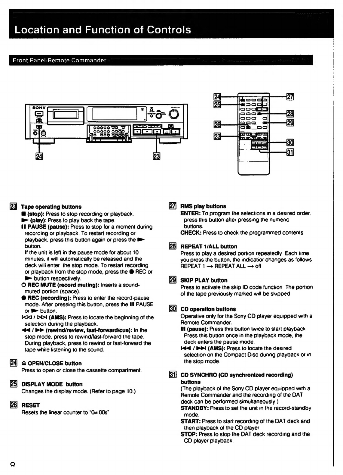
Front
panel/remote
COMMANGET
..............ccccceserecececeereees
6
Remote
commander
operation
.............ccccessecsceseeeeneee
9
Installing
DatterieS
oo.
ee
eesecceetsereseecaereereen
9
Display
WINKOW
00000...
cc
cececteccteceecnseneaseseeeenaaones
10
COMMECHIONS
«sch
s.s5:
cession
tenses
corbsekevadietecgonesdeenrseadvavsestatences
sven
13
Rear
PANE
JACKS
eecs..ceesese
isseosevseceeseeusebuceadsveseentens
eves
13
CONNECTING
COPS
00...
ee
cceeteeeeneeeeeseesceecsesesenaenee
14
Connecting
the
remote
control
system
.............
cee
14
Connection
ExAMPleS
...........ccccsccssecesecseeessetssenscereeeees
15
CLOCK
SQUING
csscicciccssceie
ccs
eadszenscassecavsatavenssusendebsnsSbbaantonnenes
17
Setting
the
date
And
tiMe
0...
cceteetccreereeteeteenes
17
SBM
(Supper
Bit
Mapping)
function
........
eee
eceeeee
18
Cassette
loading
........cccccssescssceceescesseseessetecssenscsetecaeers
19
Recording
Before
reCOrding
...........ccssccsscsssessseeseseseesseesseereeseesseeseenes
20
Blank
section
and
sound
muted
portion
.................06
20
Absolute
time
COd@S
0.0...
ee
cesseecseesceceseesenceseeeensenees
20
RECOLGING
sissies
cssiiccaa
cites
iucescxsscwssluvdadeadeovessuipseevoressaeseteses
21
To
store
the
recording
date
and
time
........
ee
22
To
check
the
recording
date
and
time
............
cee
22
RECOFdING
MODE
0.0...
eee
ceeseeeeeeteseretecesecneetcenteneesees
23
Creating
a
sound
muted
portion
(Record
muting)
......
24
EMC
SO
ECM
faces
ots
ceccaveces
cxpactes
db
easseeedeethcetatecnestaanete
24
Fade-in/fade-out
reCording
«0.00...
eccecesseeseceteersecnees
25
CD
synchronized
recording
..........
cc
ceeeesesceseeeecnees
25
Writing
sub
codes
SUD
COGOS
iiss
cos
tedevieivsdestesdvsssintaseesiasadcaisbevadeesiecnceansataseens
26
Start
lD
ecsccsask
evs
secstssaisseensteds
vies
haba
acisteac
eed
sieee
dicdovverueats
28
Writing
automatically
during
recording
..................5
28
Writing
manually
during
recording
0.0...
eee
eee
28
Writing
manually
during
playback
(Rehearsal
fUNCtION)
220...
ccc
ceteceeeeeeeteceneseneeens
29
Adjusting
the
POSition
0...
cee
ceseceeeeeeceeeees
29
ELASING
cfeccshiserece
wise
caciaeerehi
det
ttiztientinandataieten
29
Digital
Audio
Tape
DAT
(Digital
Audio
Tape)
is
a
new
recording
system
which
digitalizes
the
audio
signal
and
records
it
on
a
DAT
cassette
tape.
DAT
records
the
audio
signai
by
converting
the
analog
sound
into
a
digital
signal.
This
converting
system
is
called
the
PCM
(Pulse
Code
Modulation),
and
its
accurate
processing
of
the
audio
signal
allows
recording/playback
with
lower
wow
and
flutter,
wider
dynamic
range,
lower
distortion
rate,
and
superb
signal-to-noise
ratio.
PrOQrAM
NUMDBETS
..........-cssscesececssserseeteeeacesscesceescetsseaceessees
30
Writing
automatically
during
recording
............:cccee
30
RENUMDONING::.
05
a
cccecaeseevsctes
Goetegsektessrtintosiesdscuntesavens
31
Er
Sing):.sisces
Seca
cbeciestds
Nickeas
daveravbertecevteneteecete
ae
vabenees
31
SKID
ID
sigesstestsiteeteveestcsteateraiieitacing
ian
Aaa
eet
32
Writing
during
reCOrding
.........
ee
eeeeeetceneeteeteeeeee
32
Writing
during
playback
(Rehearsal
function)
.............
32
EASING
sick
soicadavsceysidenceacsis
hviteietcaeveaen
iain
atien
32
EMO
ID
os
sess
disedie
eo
betadeacs
bt
dcnenes
seacoast
eter
iiebiaseecrebaee
33
Writing
during
reCOrding
..........
eee
escessesreeteceeeeeenees
33
Writing
during
playback
(Rehearsal
function)
.............
33
EF
ASIN
ecesi
vecsbecessevseessetedaceauentacesescanereoeabadseqaceniieuscuoats
34
Playback
Playback
2328.03
be
a
eR
ee
34
Display
WINGOW
..0........cececccecetecetecesectsecsseraseseenteseens
35
Various
playback
Operations
...........
cc
eeeetectsenseesenenens
36
Fade-in/fade-out
play
00.0.0...
ccecesecseterserseeseeseeseneees
36
Repeat:
play
csseiscciisds
Sisaci
dieser
iia
svi
esens
helen
bettas
36
Automatic
music
sensor
Operation
...........:cceececesreeeeee
37
MUSIC/SCAN
33.scsedeseleissstcnmatnescedboceiiasdad
ances
37
Designating
the
desired
Selection
............eeeeenees
38
SKIP)
PlAY
=...
cesasthsscccesicnticdsrcceastecinsvaitriededell
eee
38
Auto
play:
restarting
playback
after
rewinding.............
38
Random
Music
Sensor
(RMS)
operation
...............66
39
Timer
activated
Operation
............cccecscccssecesseeerscesseeesseeeenee
40
Timer
activated
reCOrding
20.0.0...
eeeeeseeceeerseeeeneeseens
40
Timer
activated
playback
......
ccc
cree
ceneees
40
Additional
information
MainienanCe
...
sedis
Heciicie
etn
ionghciinveecevsteveu
neers
41
Cleaning
the
Cabinet
oo...
eee
ccteceseeneeseeneees
4
Cleaning
the
head
........
cece
csecreeeecrseeecsseneseesseeenes
41
Guide
to
the
serial
copy
management
system..................
42
TrOUDIESNOOTING
.........
eee
cess
cescseeeetssteeeeeteceseesteessenee
rere
44
SPeCHICAUNONS
ss
ssciis.siceceied
eden
Gaeeaesedarterseasicsandtcaecdatar
tens
47
in
addition,
various
control
codes
called
sub
codes
can
be
written
on
the
DAT
cassette
separately
from
the
audio
signal.
They
are
written
for
a
variety
of
convenient
playback/tape
editing
operations,
and
except
for
the
|
absolute
time,
can
be
rewritten
after
audio
signal
recording
has
been
completed.