2.
FRONT PANEL
FACILITIES
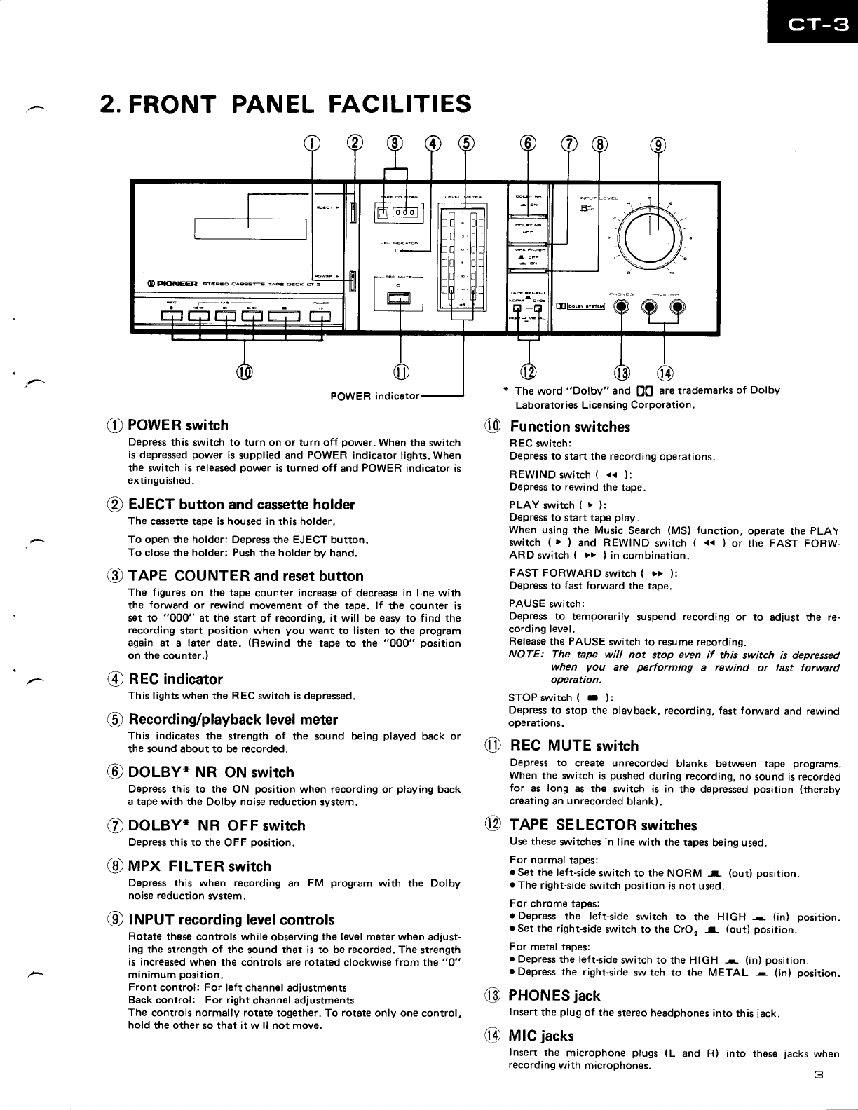
C POWER
switch
Depress
this switch to turn on or turn off power. When the switch
isdepressed
power issuppliedand POWER indicator lights.When
the switch is released
power isturned off and POWER indicator is
extingu
ished.
€) EJECT
buttonandcassetteholder
The cassettetape ishoused in this holder.
To open the holder: Depressthe EJECT button.
To close
the holder: Push
the holderby hand.
@rape couNTERandresetbutton
The figures on the tape counter increaseof decreasein line with
the forward or rewind movement of the tape. lf the counter is
set to "0OO" at the start of recording, it will be easy to find the
recording start position when you want to listen to the program
again at a later date. (Rewind the tape to the "000" position
on the counter.)
@ RECindicator
This lights
when the REC switch isdepressed.
@ Recording/playbacklevel
meter
This indicates the strength of the sound being played back or
the sound about to be recorded.
@ooleY* NR
oNswitch
Depressthis to the ON position when recording
or playing back
atapewith the Dolby noisereductionsystem.
€) DOLBY* NR OFFswitch
Depressthis to the OFF position.
@nnrx FILTER
swatch
Depressthis when recording an FM program with the Dolby
noisereductionsystem.
@ truPUfrecording
levelcontrols
Rotate these controls while observingthe levelmeter when adjust-
ing the strength of the sound that is to be recorded. The strength
is increasedwhen the controls are rotated clockwise from the "0"
minimum position.
Front control: For left channel
adjustments
Backcontrol: For right channeladjustments
The controls normally rotate together. To rotate only one control,
hold the other so
that it will not move.
@Function
switches
REC switch:
Depressto start the recording operations.
REWINDswitch
( << l:
Depress
to rewind the tape.
PLAYswitch(>):
Depress
to start tape play.
When using the Music Search (MS) function, operate the PLAY
switch (> ) and REWIND switch ( << ) or the FAST FORW-
ARD switch ( >> l in combination.
FAST FORWARD switch ( >> ):
Depressto fast forward the tape.
PAUSEswitch:
Depress to temporarily suspend recording or to adlust the re-
cordinglevel.
Releasethe PAUSE switch to resumerecording.
NOTE: The tape will not stop even if this switch is depressed
when you are pertorming a rewind or fast forward
operation.
STOPswitch(r ):
Depress
to stop the playback, recording, fast forward and rewind
operations.
RECMUTE
switch
Depress to create unrecorded blanks between tape programs.
When the switch is pushed
during recording,
no soundisrecorded
for as long as the switch is in the depressedposition (thereby
creating
anunrecorded
blank).
TAPESELECTOR
switches
Usethese
switchesin line
with the tapes
beingused.
For normaltapes:
. Setthe left-side
switchto the NORM r (out) position.
. The right-side
switchposition isnot used.
For chrome tapes:
. Depress the left-side switch to the HIGH - (inl position.
. Setthe right-side
switchto the CrO" -r (out) position.
For metal tapes:
. Depress
the left-side
switchto the HIGH ^ (in)position.
.Depress the right-side
switch to the METAL r (in) position.
PHONES
jack
Insert
the plug
of the stereoheadphones
into this
jack.
MIC
jacks
Insert the microphone pluss (L and R) into
recording
with microphones. thesejacks when
3
@
@
@
@
Theword "Dolby" and QQ aretrademarks
of Dolby
Laboratories
Licensi
ngCorporation.