Akai GXC-725D User manual

Operator's Manual No tic e d.'
Ins truc tions
g_ Kr qp ffi
La cassette dans I'illustration n'est pas
un acc6ssoire standard.
ATTENTION:
Ne pas exposer cet appareil d I'humidit6
ou d la pluie.
Bedienungsanleitung
ss
rer
Die Cassette im Bild ist nicht im Stand-
ard-zubehijr einbegriffeu.
ACHTUNG:
Schiitzen Sie das Gerdt vor Regen und
Feuchtigkeit.
W
Cassette tape in photograph not included
in standard accessories.
WARNING:
To prevent lue or shock hazard, do no1
expose this appliance to rain or mois
ture-
,.'
lMANUFACTUREO & DISTRIBUTED BY AKAI ELECTRTC CO., LTD./AKAI TRAOING CO.. LTD./AKAI AMERICA LTD.

INTRODUCTION
Your new Front Loading type Tape Deck is made of the finest
materials and incorporates the very latest in recording and
playback techniques. Itr addition to the features outlined in
this mauual, AKAI's superior A.D.R. (automatic distortion
reduction) System which changes recording equalizer charaQ-
teristics according to the signal'levei of a celtain frequency
bal1d to achieve low distortion over an extended frequency
range is alsoiincorporated in this model. This together with
many -ot'her outstandiug features including Akai's 3-head
cassetle system with GX recording and playback heads and
Dolby NR Systcm provides incotnpareble cassette performance
if the macliine is operated properly.
We, therefore, urge you to READ THIS MANUAL THOR-
OUGHLY BEFORE ATTEMPTING OPERATION.
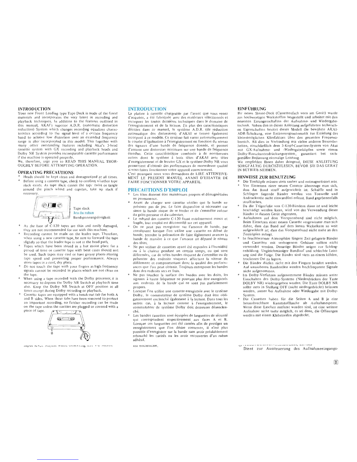
OPERATING PRECAUTIONS
* Heads should be kept clean and demagnetiTed at all times.
* Before usiug a cassette tape, chec|< to coulirm Vrirether tape
slack exists, As tape slack causes the tape twist or tangle
arourld the pinch wheel and capstan, take up slack if
necessary.
Tape slack
Jeu du ruban
Bandspannungslosigkeit
As the base of C-120 tapes are thin and easily damaged,
they are not recommended for use with this machine.
Recording cannot be made on the leader tape' Therefore,
when using a new cassette tape, be sure to forward the tape
slightly so that the leader tape is not in the head path.
Tapes which have been stored in a hot moist place lor a
period of time or cassette tape with bent cases should not
be used. Such tapes may curl or have greasy places altering
tape speed and preventing proper performance, Always
store tapes in a cool, drY Place.
Do r-rot touch the tape with your lingers as high frequency
signals cannot be recorded in places which are not clean on
the tape.
When using a tape recorded with the Dolby processor, it is
necessary to deptess the Dolby NR Switch at playback time
also. Keep the Dolby NR Switch at OFF position at all
times except during Dolby recording or playback'
INTRODUCTION
La platine i cassette chargeable par I'avant que vous venez
d'acqu6rir, a 6t6 fabriqu6e avec des mat6riaur s6lectionn6s et
incorpore les toutes dernidres techniques dans le domaine de
fenregistrement et de la lecture. En plus des caract6ristiques
d6crites dans ce manuel, le systdme A.D.R. (de r6duction
automatique des distorsions) d'AKAI se trouve 6galement
incorpor6 i ce moddle. Ce systdme fait variel automatiquement
la courbe d'6galisation i l'enregistrement en fonction du niveau
des signaux d'une bande de frequence donn6e, et permet
d'assurer une distorsion minimum sur une bande de fr6queuce
6tendue. Cette caract6ristique combin6e i de nombreuses
autres dont le systdme i trois tOtes d'AKAI avec t6tes
d'enregistrement et de lecutre GX et le systdme Dolby NR vous
permeitent d'obtenir des performances de merveileuse qualit6
si vous faites fonctionner votre appareil corectement'
C'est pourquoi nous vous demandons de LIRE ATTENTIVE-
MENT LE PRESENT MANUEL AVANT D'ESSAYER DE
FAIRE FONCTIONNER VOTRE APPAREIL.
PRECAUTIONS D'EMPLOI
* Les totes doivent dtre maintenues propres el d6magrr6tis6es
ell permanellce.
* Avant de charger une cassette v6rifier que la bande ne
pr6sente pas de jeu. Le faire disparaitre si n6cessaire car
sinon la bande risque de se tordre et de s'emm6ler autour
du galet-presseur et du cabestan.
Le ruband des cassette C-120 6tant extrdmement mince et
fragile, leur emploi est d6conseil16 sur cet appareil'
On ne peut pas enregistrer sur l'amorce de bande, par
cons6quent lorsque I'on utilise une cassette en d6but de
bande, prendre la pr6caution de faire l6gdrement avancer la
bande de manilre i ce que I'amorce ait d6pass6 le niveau
des tdtes.
Ne pas utiliser de cassettes ayant 6,t6 expos6es i I'humidit6
ou i la chaleur pendant un certain temps, ou qul sont
d6form6es, car de telles bandes risquent de s'emm6ler ou de
pr6senter des endroite visqueux affectant la vitesse de
d6filement et compromettant donc la qualit6 des perforni
ances que l'on peut obtenir. Toujours entreposer les bandes
dans des endroits secs et frais.
Ne oas toucher la surface des bandes avec les doits, les
signiux i haute fr6quence ne pouvant plus Otre enregistrds
aux endroits de la bande qui ne sont pas parfaitement
propres.
Lorsque l'on utilise une cassette enregistr6e avec le systdme
Dolby, le commutateur de systdme Dolby doit 6tre obii-
gatoirement enclench6 6galement i la lecture. Daus tous les
autres cas, i la lecture comme i l'enregistrement, le
commutateur de systdme Dolby doit demeurer d6senclen-
ch6.
Les bandes cassettes sont 6quip6es de languettes de s6curit6
qui correspondent respectivement aux faces A et B.
Lorsque ces languettes ont 6t6 cass6es afin de prot6ger un
enregistrement que l'on d6sire conserver, il n'est plus
possible d'enregistrer sur la baude sans avoir prealablemeut
rebouch6 les cavit6s ou les avoir recouvertes d'un ruban
adh6sif.
CSL trITCICIICIIU.
EINFUHRUNG
Ihr neues Stereo-Deck (Cassettenfach vorn am Gerdt) wurde
aus hochwertigen Werkstoffen hergestellt und arbeitet mit den
neuesten Errungenschafteu der Aufnahme- und Wiedergabe-
technik. Neben den in dieser Anleitung aufgefiihrten technisch-
en Eigenschaften besitzt dieses Modell die bewdhrte AKAI-
ADR-Schaltung, eine Entzerrungsautomatik zur Erzielung des
kleinstmirglichen Klirrfaktors iiber den gesamten Frequenz-
bereich. All dies in Verbindung mit vielen anderen Besonder-
heiten, einschlie8lich dem 3-Kopf:Cassetten-System von Akai
mit GX-Aufnahme- und -Wiedergabekdpfen sowie einem
Dolby-Rauschunterdriickungssystem, garantiert bei sach-
gemdBer Bedienung einmalige Leistung'
Wir empfehlen Ihnen daher dringend, DIESE ANLF'ITUNG
SORGFALTIG DURCHZULESEN, BEVOR SIE DAS GERAT
IN BETRIEB NEHMEN.
HINWEISE ZUR BBNUTZUNG
* Die Tonkirpfe mtssen stets sauber und entmagnetisiert sein.
* Vor Einsetzen einer neuen Cassette iiberzeuge man sich,
dass das Band straff aufgewickelt ist. Schalffe und in
Schlingen liegende Bdnder werden von Tonwelle und
Andruckrolle nicht einwandfrei erfasst. Band gegebenenfalls
straffziehen.
* Da die Trdgerfolie von C-l20-Bdndern diinn ist und leicht
beschddigt werden kann, wird von der Verwendung dieser
Bdnder in diesem Gerdt abgeraten.
Aufnahmen auf dem Vorspannband sind nicht mciglich.
Beim Einsetzen einer neuen Cassette vergewissere man sich
daher, dass das Band auf dem leeren Wickelkem so weit
aufgewikkelt ist, dass das Vorspannband nicht mehr an den
Tonkdpfen anliegl.
In feuchtwarmer Atmosphdre ldngere Zeit gelagerte Bdnder
und Cassetten mit verbogenem Gehduse sollten nicht
verwendet werden. Derartige Bdnder neigen zur Schling-
enbildung. Ungleichmdssiger Bandlauf und schlechte Leist-
ung sind die Folge. Die Bdnder sind stets an einem kbhlen'
trockenen Ort zu lagern.
Die Bdnder diirfen nicht mit den Fingern beriihrt werden.
Auf unsduberen Bandstellen werden hochfrequente Signale
nicht aufgenommen.
Im Dolby-Verfahren aulgenommene Bdnder miissen unter
Einschalten des Dolby-Systems (Niederdriicken der Taste
DOLBY NR) wiedergegeben werden' Die Taste DOLBY NR
sollte stets in Stellung OtsF (nioht niedergedriickt) belassen
werden, ausser bei Aufirahme oder Wiedergabe mit Dolby-
System.
Die Cassetten haben fiir die Seiten A und B je eine
herausbrechbare Kunststofflasche als Aufnahmesperre.
Wenn diese Laschen entfemt worden sind, ist eine weitere
Aufirahme nicht mehr m6glich, es sei denn, die Offnungen
werden mit einem Klebstreifen abgedeckt.
Dient zur Aussteuerung des Aufnahmeeingangs-
Cassettc tapes are equipped with a break-out tab for both A
and B sides. When these tabs have been removed to protect
an important recording, no further recording can be made
on the tape unless the cavities are plugged or covered with a
piece of tape.
E

BEDIENUNGSELEMENTE
CONTROLS COMMANDES
IIff I
tr

C pownn SwITCH
@ cnssnrrn RECEPTACLE (with tape view
window)
Opens when the Eject Key is depressed. To load a
tape, depress Eject Key and insert cassette with tape
facing the heads and then close lid. The oil-damped
eject system makes no irritating mechanical noise.
@ INDEX COUNTER AND RESET BUTTON
Tape indexing is made easy with this 3-digit Index
Counter. Provides an easy reference for quickly
locating positions on the tape. To reset to "000",
depress Reset Button.
@ rrnr vu METER
Indicates left channel recording and playback levels.
@ pnIT LEVEL INDICATOR
+7 dB
This indicator lights at +7 dB above "0" VU. At
normal recording, VU Meter response is usually
accurate, but when pulsive signals enter, such as
signals from percussion instruments, etc., the re-
sponse is slow and therefore lower than actual
volume is registered. +7 dB peak level indicator acts
as a warning device by lighting at excessive actual
input. Because for recording with the least possible
noise, it is advantageous to keep the recording level
as high as possible not to exceed the level at which
distortion occurs due to excessive input, for best
recording results, the level range in which this +7 dB
light flickers at largest input parts only is most ideal.
@ Rrcrn vtl METER
Indicates right channel recording and playback
levels.
@ RECORDING INDICATOR LAMP
Lights when the Recording Key is depressed.
@ nomv NR TNDICAToR LAMP
Lights when the Dolby NR Switch is at ON
position.
@ ornpur LEVEL coNTRoL
Adiusts output volume and headphone output level.
@ RIGHT CHANNEL RECORDING LEVEL
CONTROL
Controls right channel line (or microphone) record-
ing input level. Adjust while observing right VU
Meter.
6} LEFT CHANNEL RECORDING LEVEL
CONTROL
Controls left channel line (or microphone) recording
input level. Adjust while observing left VU Meter.
C copruurATEUR D'ALTMENTATToN (powER)
@ COWERCLE DE LOGEMENT DE CASSETTE
(avec fendtre de contrdle de bande)
S'ouvre lorsqu'on appuie sur le bouton d'6jection.
Pour charger une bande, appuyer sur le. bouton
d'6jection et introduire une cassette avec le cdt6
d6couvert de la bande face aux t€tes puis refermer le
couvercle.
Le systdme d'6jection amorti par huile ne produit
aucun bruit m6canique irritant.
@ COMPTEUR ET BOUTON DE REMISE A ZERO
Ce compteur de 3 chiffres permet de rep6rer
facilement un passage sur la bande. Pour l'annuler,
appuyer sur le bouton de remise i z,6ro.
@ vu uErnn DE GAUCHE
Fournit I'indication des niveaux d'enregistrement et
de lecture du canal gauche.
@INDICATEUR DE VALEUR DE CRETE (PEAK
LEVEL)
+7 dB
Cet indicateur s'allume A +7 dB au-dessus de "0"
VU. Dans les conditions normales d'enregistrement,
le VU mdtre fournit g6n6ralement une indication
suffisamment pr6cise; il possdde cependant un cer-
tain degr6 d'inertie qui ne lui permet pas de r6agir
instantan6ment aux impulsions brdves, comme par
exemple colles fournies par un instrument i percus-
sion et, dans ce cas ld, le volume enregistr6 est
inf6rieur i la r6alit6. Cet indicateur d6 valeur de
crOte de +7 dB fonctionne d la manidre d'un signal
d'alarme en s'allumant lorsque le niveau d'entr6e
devient excessif. Pour obtenir le maximum de clart6
d'enregistrement, on a int6r6t ir fixer le niveau
d'enregistrement aussi haut que possible sans d6pas-
ser le niveau i partir duquel une entr6e excessive
entraine des distorsions. Pour un r6sultat optimum,
fixer 1e niveau d'enregistrement de manidre i ce que
cette lampe ne clignote que pour des valeurs de
cr0te les plus importantes.
@ vu METRE DE DRoITE
Fournit I'indication des niveaux d'enregistrement et
de lecture du canal droit.
@ T-IIVTpE TEMOIN D'ENREGISTREMENT
S'allume lorsque I'on enfonce 1a touche d'enregistre-
ment.
@ L.q.Mpn rEMorN DU sysrEME DoLBy (DoLBy
NR)
S'allume quand le commutateur de systdme DOLBY
est enclench6.
C NETZSCHALTER (POWER)
@ clssnrrENFACH
(mit Bandsichtfenster)
Springt durch Driicken der Auswurftaste auf. Zum
Einlegen einer Cassette die Auswurftaste driicken,
die Cassette mit der Bandseite zu den Tonk6pfen
einlegen und dann den Deckel schlieBen.
Das Auswurfsystem mit Oldempfung verursacht
kein ldstiges Mechanikgerdusch.
@ nlNozAHLwERK r.lND RI]cKSTELLTASTE
Das dreistellige Bandzdhlwerk gestattet ein leichtes
Verfolgen des Bandlaufs und ein rasches Auffinden
bestimmter Bandstellen. Riickstellen auf "000"
erfolgt durch Niederdriicken der Riickstelltaste.
@ AUSSTEUERUNG SINSTRUMENT LINKS
Zur Anzeige des Aufnahme- und Wiedergabepegels
des linken Kanals.
@ iEnnsrnuERr.JNGSANZErcE (rEAK LEVEL)
+7 dB
Diese Anzeige leuchtet bei +7 dB iiber 0 VU auf. Bei
normalen Aufnahmebedingungen sprechen die
Aussteuerungsinstrumente meistens ausreichend
schnell an; im Falle von impulsformigen Eingangs-
signalen, wie z.B. von Schlaginstrumenten und
dergleichen, ist das Ansprechen zu langsam, und ein
zu geringer Eingangspegel wird angezeigt. Die +7
dB-SpitzenpegefAnzeige dient durch Aufleuchten
als Warneinrichtung vor zu hohem Eingangspegel.
Fiir eine Aufnahme mit minimalem Hintergrund-
rauschen sollte der Aufnahmepegel moglichst hoch
sein, ohne jedoch den Punkt zu iiberschreiten, an
dem Verzerrung infolge zu starken Eingangspegels
eintritt. Aus diesem Grunde ist derjenige Aus-
steuerungsbereich ideal, in dem die +7 dB-Anzeige
nur bei den lautesten Tonen kurz aufflackert.
@ IUSSTTUERUNGSTNSTRUMENT RECHTS
Zur Anzeige des Aufnahme- und Wiedergabepegels
des rechten Kanals.
@ a un rueHM EANZEIGE LA MPE
Leuchtet auf, wenn die Aufnahmetaste betdtigt
wird.
@ DOLBYZAHLANZEIGELAMPE (DOLBY NR)
Leuchtet auf, wenn der Dolbyzahl-Schalter in Stel-
lung ON steht.
@ IUSCINGSPEGELREGLER
Dient zur Einstellung des Lautstdrke- und Kopf-
hbrer-Ausgangspegels.
@ AUSSTEUERUNGSREGLER, LINKS
Dient zur Aussteuerung des Aufnahmeeingangs-
tr

Q?) STOP/EJECT KEY
Functions as a Stop Key during operating mode,
and as an Eject Key during stop mode.
@ nrconprNc (REC) KEy
Depress this key and while holding it depressed
depress the Play Key to effect recording mode.
* The Recording Key must always be depressed first.
(4 RnwrNo(< ) KEY
Rewinds tape at high speed.
@pr,lv( > )KEY
Advances tape for playback and recording modes.
@ n.qsr FoRwARD ( >>) KEY
Advances tape at high speed.
@ p,lusn rny
Depress to momentarily suspend tape travel during
recording or playback. Convenient for tape editing.
* Pause Control does not function during Fast Forward or
Rewind.
@ rlpn MoNrroR swrrcu
To monitor recorded signals or for playback, set to
TAPE position. To monitor program source; set to
SOURCE position. Switching to and from TAPE
and SOURCE positions during recording enables the
operator to compare signals just recorded with the
progfam source.
€D upB SELECToR
This control should be positioned to correspond
with the tape being used. That is, for low-noise
tapes, position it to LN, for low-noise, high-output
tapes to LH, for chrome tapes to CrOz and for
ferrochrome tapes to Fe-Cr.
* Refer to STANDARD REFERENCE AND RECOM-
MENDED TAPES.
@ tolnv NR swrrcH
Setting the Dolby NR Switch to CN position
activates the Dolby circuit to raise lorv lerel signals
before they are recorded and lowers them by
precisely the same amount during playback. This
process eliminates extraneotrs and superimposed
noise, thus also eliminating tape hiss.
* When using tape recorded with the Dolby process, it is
necessary that this switch be set to ON position at
' playback also.
* fhe Dolby NR Indicator Lamp lights when the Dolb.y
NR Sw'tch is depressed.
@ MPX FIL,TER SWITCH
Prevents disiurbance caused by the 19 kHz pilot
signal during FM stereo broadcast recording with
the Dolby System through an FM receiver or tuner.
€) BOUTON DE NIVEAU DE SORTIE
Permet de r6gler le volume de sortie et le niveau de
sortie i l'6couteur.
@ norrroN DU NTvEAU D'ENREGTsTREMENT DU
CANAL GAUCHE
Permet de r6gler le niveau d'entr6e d'enregistrement
de ligne du canal gauche (ou de microphone).
Ajuster tout en observant le VU mdtre gauche.
O eOUToN DU NIVEAU D'ENREGISTREMENT DU
CANAL DROIT
Permet de r6gler le niveau d'entr6e d'enregistrement
de ligne du canal droit (ou de microphone). Ajuster
tout en observant le VU mdtre droit.
.T? TOUcTTE D'ARRET ET D,EJECTIoN
(sToP/EJECT)
Fonctionne comme une touche d'arrdt en oours
d'utilisation, et comme urie touche d'6jection i
l'arrdt.
(1' TOUCHE D'ENREGISTREMENT (REC)
Appuyer sur cette touche et tout en la maintenant
enfonc6e, appuyer sur la touche d'6coute pour
passer au mode d'enregistrement.
* La touche d'enregistrement doit toujours 6tre enfonc6e
la premidre.
(II rOucrrn DE REMBoBINAGE RAPIDE ( .- )
Permet de rembobiner la bande i vitesse rapide.
CDroucnBDELECTURE( > )
Fait ddfiler la bande dans le sens avant pour la
lecture ou I'enregistrement.
Q0 roucHns DE BoBTNAGE RAnTDE ( >> )
Permet le rembobinage de bande ) vitesse rapide.
€z) roucur DE pAUSE (pAUSE)
L'enfoncer pour interrompre momentan6ment le
d6filement de la bande au cours de I'enregistrement
ou de la lecture. Extr€mement pratique pour le
montage de bande.
* Le commande de pause ne fonctionne pas durant
I'avance rapide ou rembobinage.
itD covtuurATEUR DE MoNTToRING DE BANDE
Pour contrdler la qualit6 d'un enregistrement en
cours ou en reproduction r6gler sur la position
TAPE. Pour contrdler la source r6gler sur la position
SOURCE. Passer alternativement de 1a position
TAPE e la position SOURCE permet un double
contrOle. En comparant la qualit6 de I'enregistre-
ment avec celle de la source.
pegels (Direkt- oder Mikrofoneingang) des linken
Kanals. Den Regler unter Beobachtung des linken
Aussteuerungsinstrumentes bedienen.
@ nussrBuERUNGsREG LER, RECHTS
Dient zur Aussteuerung des Aufnahmeeingangs-
pegels (Direkt- oder Mikrofoneingang) des rechten
Kanals. Den Regler unter Beobachtung des rechten
Aussteuerungsinstrumentes bedienen.
@ srop/luswuRFTASTE (srop/EJECT)
Wdhrend des Betriebs arbeitet diese Taste als Stop-
taste und wdhrend des Stillstands als Auswurftaste.
@IUTN.IHMETASTE (REC)
Zur Aufnahmevorbereitung wird diese Taste zusam-
men mit der Starttaste gedriickt.
* Die Aufnahmetaste muB hierbei zuerst gedrtckt werden.
(EnucruuFTASTE ( << )
Fiir Riicklauf des Bandes mit erhohter Geschwindie-
keit.
@sr.lnrusrE( > )
Bewirkt Bandvorlauf fiir Aufnahme und Wieder-
gabe.
@scnxurERvoRLAUF( >> )
l.-iir den Vorlauf des Bandes mit erhohter Gesch-
windigkeit.
@p.nusnurAsTE (PAUsE)
Unterbricht den Bandlauf bei Aufnahme oder
Wiedergabe ohne die eingestellten Aufnahme/
Wiedergabefunktionen aufzuheben. Losen derTaste
durch erneutes Niederdrircken.
* Pausenregler arbeitet nicht bei schnellen Vorlauf und
Riicklauf.
@ n,toi.uronscHAt-TER
Bringen Sie diesen Schalter in die Stellung TAPE, um
aufgenommene Signale mitzuhoren oder auch bei
der Wiedergabe. Zum Mithoren der Programmquelle
bringen Sie den Schalter in die Stellung SOURCE.
Durch Hin- und Herschalten zwischen den Stel-
lungen TAPE und SOURCE wdhrend der Auf-
nahme, konnen Sie die gerade aufgenommenen
Signale mit der Programmquelle vergleichen.
@ seNnwlHl (TAPE sELECToR)
Die Stellung dieses Schalters richtet sich nach der
verwendeten Bandsorte. Fiir Low-Noise-Bdnder stel-
len Sie ihn auf LN, fiir rauscharme Hochleistungs-
bdnder auf LH, fiir Chrom-Bdnder auf CrOz, und
fiir Ferrochrom-Bdnder auf Fe-Cr.
* Siehe REFERENZ- UND EMPFOHLENE BANDSOR-
TEN.
tr

@ uEnopHoNE JACK
Accommodates stereo headphones of 8 ohms im-
pedance for monitoring or private headphone listen-
ing.
@) MICROPHONE JACKS (left and right). ..
When the microphones are connected, line inputs
are automaticallY cut-o ff.
24 LINE OUTPUT JACKS (left and right)
Connects to tape inputs of external amplifier or
tape recorder'
2i LINE INPUT JACKS (left and righl )
Connects to tape outputs (or Rec' outputs) of
external source.
[g) sET-TCTNUR DE BANDE (TAPE SELECTOR)
Cette commande doit 6tre positionn€ pour corres-
pondre i 1a bande utilis6e. C'est-ir-dire, pour les
tandes i faible bruit, la positionner i LN, pour les
bandes i haut rendement i faible bruit ir LH, pour
les bandes chrome i CrOz et pour les bandes
ferrochrome ir FeCr.
* R6f6rer les tsANDES STANDARD ET RLCOMMAN-
DEtsS.
OO COMMUTATEUR DE SYSTEME DOLBY (DOLBY
NR)
Le circuit DOLBY se trouve aliment6 lorsque l'on
enfonce le commutateur de systeme DOLBY, les
signaux de faible puissance sont amplifi6s juste
avant d'€tre enregistr6s pour 6tre r6duits trbs pr6-
cis6ment tl'autant i la lecture' Au cours de ce
proc6d6 tous ies parasites se trouvent 61imin6s et en
particulier le souffle de bande est supprim6'
; Lo.rqu" I'on utilise une bande enregistr6e avec le
systdme DOLIIY il est nr5cessaire d'enfoncer ce com-
mutateur i la lecture egalement'
* La lampe indicatrice Dolby N R s'allume quand on
appuie sur le commutateur Dolby NR'
Oi COMMUTATEUR DE FILTRE MPX
Empdchent le d6rangement caus6 par le signal pilote
d tS tFIz durant I'enregistrement de radio-diffusion
st6r6ophonique de FM avec le systdme Dolby au
moyen d'un recepteur de FM ou syntonisateur'
@ pntsn DE cASQUE (PHoNE)
Adapt6e au casque de B Ohm d'rmp6dance pour le
monitoring ou 1'6coute individuelle'
09 PRISES JACKS DE MICROPHONE (gauche et
droit)
Quand les microphones sont branch6s, les entr6es de
ligne se trouvent coup6es automatiquement'
@ prusn DE SORTIE LIGNE (LINE OUT) (gauche et
droite)
Les raccorder aux entr6es magn6to de I'ampliex-
terne ou du magn6toPhone.
@D pntsEs D'ENTREE LIGNE (LINE lN) (gauche et
droite)
Les raccorder aux sorties magneto de Ia source
exterieure.
CHARGEMENT DU RUBAN
Les num6ros dans la photographie indiquent I'ordre du
proc6d6 de charger la cassette'
@ noI-nYzIHLSCHALTER (DoLBY NR)
Niederdriicken der Taste DOLBY NR bewirkt, daB
durch die Dolby-Schaltung die Signale mit kleinem
Pegel bei der Aufnahme mehr als die Signale mit
miitlerem und hohem Pegel verstdrk werden'
Dadurch ist der Abstand der niedrigen Signalpegel
vom Rauschpegel tles Bandes 916Ber geworden' Bei
der Wieclergabe wird die Wirkung dieser Anhebung
durch eine entgegengesetzt wirkende Schaltung
soweit kompensiert, da8 das Bandrauschen nahezu
unhorbar wird.
+ Fiir die Wiedergabe von im Dolby-Verfahren aufgenom
menen Bdndern ist es notwendig, den Schalter ehe falls
in Stellung ON (niedergedrtickt) zu bringen'-
* Beim Dricken des Dolby-NR-schalters leuchtet die
DolbY N R-AnzeigelamPe auf'
@ MPX FILTERSCHAI ER
Zur Verhinderung der verursachten Storung durch
die 19 kHz Uberwachungslampe bei der Aufnahme
des FM Stereo-Rundfunks mittels Dolby-System
durch den Empfdnger und die Abstimmungsvor-
rlchtung.
@ ropru0nERBUCHSE (PHoNE)
Fiir den AnschluB eines 8-Ohm-Stereokopthorers
zum Mithoren des Aufnahmetons oder um ungestbrt
zu horen.
q3 MIKROFON-BUCHSEN (links und rechts)
Beim AnschluB der Mikrofone werden die Direkt-
eingringe automatisch auBer Funktion gesetzt'
@Rcn-sTEcKERAUSGANG (LINE oUT) (links und
rechts)
Zum Anschliessen an Tonbandeingdnge von Ver-
stdrkern und Tonbandgerdten'
@nc.q.-sTTcKEREINGANG (LINE IN) (links und
rechts)
Zum inschlieBen an Tonbandausghnge (oder Rec-
Ausgdnge) von Tonquellen.
EINLEGEN DER CASSETTE
Die Zahlen im Foto geben die Reihenfotge beim
Einlegen der ('assetle an.
TAPE LOADING
The numbers in the photograph indicate the order ot
cassette loading Procedure.
&
f1.
"',::
E

CASSETTE TRACK SYSTEM
SIDE B
SIDE B
SIDE A
SIDE A
(L)
(R)
(R)
(L)
HEAD
DIRECT FTJNCTION CHANGE CONTROL
This model employs full direct function change
control for speedy mode selection' The necessi-
ty of depressing the Stop Key prior to-changing
modes is eliminated' Direct Function Change to
recording facilitates easy add-on recording'
SYSTEME DE COMMANDES A CHANGB
MENT DE FONCTION DIRECT
Ce moddle est 6quip6 d'un systbme de com-
mandes ) changement de fonction direct qui
Dermet de s6lectionner rapidement le mode de
ionctionnement choisi, sans avoir besoin de pas-
ser par la touche d'arr6t.
SYSTEME DE PISTE
BANDE B
BANDE B
BANDE A
BANDE A
(G)
(D)
(D)
(G)
TETES
DTREKTER FUNKTIONSWECHSEL
Bei diesem Modell wird schnelle Bedienungs-
wahl durch unmittelbaren Funktionswechsel er-
moglicht. Dadurch eriibrigt es sich, die..Stop-
tasie vor jedem Bedienungswechsel zu drticken'
SPURLAGE DER CASSETTEN
SEITE B
SEITE B
SEITE A
SEITE A
(L)
(R)
(R)
(L)
KOPF
This model employs a 4-track recording/playback
system. The first half of the stereophonic recording or
playback takes place on tracks 1 and 2' The second
Laft takes palce on tracks 3 and 4 after the cassette has
been inveried. Recording and playback time depend
upon the length of the tape (C-30, 30 minutes; C-60,
60 minutes, etc.).
Monaural and stereo recorded tapes can be played back
on either stereo or monaural cassette recorders without
any loss in quality' Because the total track width of the
lefi and right channels is equal to that of the monaural
track, the playback head will scan both left and right
"t urrrr.tt togeiher. This results in automatic mixing of
left and ,ight "hutttt"ls from the stereo tape for
monaural reProduction.
AUTOMATIC STOP
This machine employs a full release automatic stop' At
the end of the tape, the automatic stop will separate
the head block from the tape and capstan completely
to protect tape and to prevent pinch wheel wear'
Ce moddle utilise un systdme de 4 pistes d'enregistre-
ment/lecture. La premidre moiti6 de l'enregistrement
ou de la lecture si6r6o s'effectue sur 1es pistes 1 er 2'
La seconde moiti6 s'effectue sur les pistes 3 et 4 une
fois que I'on a retourn6 la cassette' La dur6e de
i "nt"gi.tr.-"nt ou de la lecture est fonction de Ia
cassetle utilis6e (30 mm avec une cassette C-30' 60 mm
avec une casselte C-60. etc.)'
Les bandes enregistr6es en st6r6o ou en mono peuvent
etrl inOlft6remment lues sur des magn6tophones i
cassette st6r6o ou mono' sans que la qualit6 de la
lecture s'en ressente. La largeur totale des pistes
correspondant aux canaux gauche et droit- en st6r6o
Ziiit'eeut" ir celle d'une piste mono, lorsqu'une
cassette-st6r6o est lue sur un magn6tophone mono' la
tOie de lecture analyse simultan6ment les pistes cor-
respondant aux canaux gauche et droit' Les.2 canaux
de la bande st6r6o se trouvent donc automatiquement
m6lang6s pour produire une lecture mono'
ARRET AUTOMATIQUE
Cet appareil est 6quip6 du dispositjf d'arret auto-
*"iiq,i". En fin de bande, le bloc de t6te se. detache de
la bande et du cabestan, ce qui protdge la bande et
6vite l'usure du gallet-Presseur'
Das Modell GXC-725D ist ein 4-Spur-Stereogerdt fiir
Aufnahme und Wiedergabe. Die erste Cassettenseite
benutzt die Spuren I und 2' die zweite Cassettenseite
die Spuren 3 und 4. Die Spieldauer von A-ufnahme und
Wiedergabe hdngt von der Ldnge des.Bandes ab (C-30 =
30 Minuten, C-60 = 60 Minuten usw')'
Mono- odei Stereoaufnahmen konnen ohne Qualitlt-
sverlust auf monauralen oder Stereo-Cassetten-
recordern wiedergegeben werden' Da die Gesamt-
spubreite von linkem und rechtem Kanal der monaura-
len Spurbreiten entspricht, tastet der Wiedergabekopf
den linken und rechten Kanal zusammen ab' Dadurch
gelangt bei monauraler Wiedergabe eines Stereobandes
iin Gimisch aus rechtem und linkem Kanal zu Gehor'
STOPPAUTOMATIK
Dieses Gerdt besitzt eine Stoppautomatik, d'h' am
Ende des Bandes werden die Kopfe vom Band und der
Antriebswelle abgehoben. Dadurch wird das Band
geschont und ein Verschleiss der Andruckrolle ver-
hindert.
tr

CONNECTIONS
For PLAYBACK
Pour la LEGTURE
Fiir WIEDERGABE
STEREO RECEIVER
(TUNER/AMPLIFIER)
RIICIlPTEUR STIlREOPHONIQUE
(TUN I.] R/AMPLI I'ICATEUR)
STEREO-EMPFANGER
(TUNER/VERSTARKER)
SPEAKERS
ENCL,INTES
LAUTSPRECHER
tr
RACCORDEMENTS ANSCHLIESSEN
For REGORDING
Pour I'ENREGISTREMENT
Fiir AUFNAHME
STEREO RECEIVF]R
(TUNER/AMPL]FIER)
RECIIPTF]UR STERIIOPHONIQtJ E
(TUNF] R/AM PLI FICAT I-]U R)
STE REO.EMPFAN GE R
(TUNER/VERSTARKER)
RECORD PLAYER WITH
CRYSTAL OR CERAMI(]
PICK-UP
TABLE I)t-l LIICTURIj
A ('hLLULL ( tltAMlQUI
OLI CRISTA L
PLATTENSPIELER MIT
KRISTAL-ODER
KERAMI KTONABNEHMER
I € € H,cooooo
, oElEo'o
a..I_|_oo
TURNTABLE WlTH
MAGNETIC CARTRIDGE
TAI]LE 1]T LF]CTURE
A CIILLU LI1 MAGNE'IIQUI
PLATTENSPIELER MIT
MAGNETTONABNEHMER
STEREO TAPE
RECORI)ER OR TAPL,
DECK
MAGNT,]TOI'HONI.] OU
PLAI'lNE STHItIlO
srEREo-ToN BeNpcrRAr
ODER
STEREO-DECK

5.
o.
PLAYBACK
Make the necessary connections as shown in CON-
NECTIONS FOR PLAYBACK.
1. Connect power cord and turn on Power Switch'
2. Depress Eject key and load a pre-recorded tape'
3. Set Monitor Switch to TAPE position'
4. Set Tape Selector to appropriate tape selection'
* Refer to STANDARD REFERENCE AND RECOMMFIND-
ED TAPES.
Depress PLAY ( - ) k.y to begin playback'
Adjust Output Level Control and external amplifier
controls.
REPRODUCTION
Effectuer les connexions n6cessaires comme il est
montr6 sur le sch6ma RACCORDEMENTS POUR LA
LECTURE,
1. Connecter le cordon d'alimentation et mettre f in-
terrupteur sur marche.
2. Appuyer sur la touche d'6jection et charger une
bande p16-enregistr6e.
3. Mettre le commutateur de contrdle sur la position
TAPE (Bande).
4. Mettre le s6lecteur de bande i la position ad6quate
pour la bande choisie.
* Se r6f,irer au TABLEAU DE REFERENCE ET DE
BANDES RECOMMANDEES.
5. Appuyer sur la touche PLAY( > )(Reproduction)
pour commencer l'6coute.
6. Ajuster le bouton de niveau de sortie et ceux de
1'amplificateur externe.
* L'arr6t automatique aura lieu i la fin de la bande. Pour
arr6ter te d6filemmt de la bande en cours d'6coute' appuyer
sur la touche STOP
* Pour la reproduction des bandes enregistrees Dolby' ap-
puyer sur le commutateur Dolby NR' (Laisser d la position
O!-F (arret) pour la reproduction normale.)
ENREGISTREMENT
Connecter la source de programme d6sir6e aux prises
d'entr6e appropri6es comme le montre le sch6ma
RACCORDEMENTS POUR L'ENREGISTREMENT.
1. Connecter le cordon d'alimentation et mettre I'in-
terrupteur sur marche.
2. Appuyer sur la touche d'6jection et charger une
bande. (Les bandes neuves donnent le meilleur
r6sultat.)
3. Mettre le compteur de repdre sur "000".
4. R6gter le commutateur de contrdle sur la position
SOURCE.
5. R6gler le s6lecteur de bande sur la position voulue
suivant le tyPe de bande utilis6e.
" Se T6f6TeT aU TABLEAU DE REFERENCE ET DE
BANDES RECOMMANDEES.
6. Pour I'enregistrement Dolby, appuyer sur le commu-
tateur Dolby NR. Pour I'enregistrement Dolby des
6missions FM, appuyer sur le commutateur de filtre
MPX 6galement.
7. Ajuster et 6quilibrer le niveau d'entr6e d'enregistre-
ment au moyen des boutons de niveau d'enregistre-
ment appropri6s tout en observant les VU mdtres.
Pour I'enregistrement optimal, seuls les signaux
d'entr6e relativement importants peuvent venir en
position "0" VU. Une distorsion se produira si
I'indicateur VU mdtre reste i la position extr6me
droite (entr6e excessive) durant I'enregistrement'
* Se r6f6rer 6galement aux paragraphes intitul6s CONTROLE
DOUBLE et Indicateur de niveau de cr6te sous l'ent€te
BOUTONS DE REGLAGE,
WIEDERGABE
Sdmtliche Anschliisse gemdB ANSCHLIESSEN FUR
WIEDERGABE vornehmen.
l Netzkabel anschlieBen und den Netzschalter betdti-
gen.
2. Auswurftaste driicken und eine bespielte Bandcas-
sette einsetzen.
3. Monitorschalter auf TAPE stellen.
4. Den Bandwahlschalter entsprechend der verwende-
ten Bandsorte einstellen'
* Siehe REFERENZ- UND EMPFOHLENE BANDSORTEN'
5. Starttaste ( > ) dri.rcken, um mit der Wiedergabe
zu beginnen.
6. Ausgangspegelregler und Regler des externen Ver-
stdrkers justieren.
+ Am Bandende tritt die die Abschaltautomatik in Funktion'
Um den Bandlauf wdhrend des Betriebs zu unterbrechen,
die Stoptaste (STOP) driicken'
* Zur Wiedergub" uot Bdndern, die nach dem Dolby-NR-
Svstem bespielt wurden, ist der Dolby-NR'Schalter zu
driicken.
AUFNAHME
Die gewiinschte Programmquelle an die entsprechenden
Eingangsbuchsen gemdB ANSCHLIESSEN FUR AUF-
NAHME anschlieBen.
l. Netzkabel anschlie8en und den Netzschalter betdti-
2. Auswurftaste driicken und eine Bandcassette ein-
setzen (neue Bdnder liefern die besten Ergebnisse)'
3. Bandzithlwerk auf "000" stellen'
4. Monitorschalter auf SOURCE stellen-
5. Bandwahlschalter entsprechend der verwendeten
Bandsorle einstellen.
+ Siehe REFERENZ- UND EMPFOHLENE BANDSORTEN'
6. Firr Aufnahmen mit dem Dolby-NR-System den
D olby-NR-S chalt er drticken. Fiir D olby-Aufnahmen
von UKW-sendungen ist ebenfalls der MPX-Filter-
schalter zu driicken.
7. Unter Beobachtung der Aussteuerungsinstrumente
die Aufnahmeeingangspegel mit den entsprechenden
Aussteuerungsreglern einstellen. Die besten Re-
sultate werden erhalten, wenn nur die verhdltnis-
mdBig starken Eingangssignale einen Zeigerausschlag
von 0 VU verursachen. Bleibt die Anzeigenadel der
Aussteuerungsinstrumente wdhrend der Aufnahme
stdndig im duBerst rechten Bereich (Eingangspegel
zu stark), so treten Verzerrungen auf.
* Siehe auch HINTERBANDKONTROLLE und Spitzenpegel-
anzeige unter BEDIENUNGSELEMENTE.
8. Nachdem der optimale Aufnahmepegel bei nieder-
gedriickter Aufnahmetaste (REC) bestimmt wurde,
die Starttaste ( > ) driicken, um mit der Auf-
zeichnung zu beginnen.
+ Automatic Stop will be effected at the end of the tape' To
stop tape travel during performance, depress STOP kev'
* Foi ptuyua"k of Dolby recorded tapes, depress Dolby NR
Switch. (Leave at OFF position for regular playback')
RECORDING
Connect desired program source to appropriate inputs
as shown in CONNECTIONS FOR RECORDING'
l. Connect power cord and turn on Power Switch.
2. Depress Eject key and load a tape (new tapes give
best results).
3. Set Index Counter to "000".
4. Set Monitor Switch to SOURCE position.
5. Set Tape Selector to appropriate tape type.
* Refer to STANDARD REFERENCE AND RECOMMEND-
ED TAPES.
6. For Dolby recording, depress Dolby NR Switch' For
Dolby recording of FM stereo broadcasts, depress
MPX Filter Switch also.
7. Adjust and balance recording input level with
appropriate Recording Level Controls while observ-
ing VU Meters. For optimum recording, only the
comparatively large input signals should touch the
"0" VU position. Distortion will result if the VU
Meter indicator remains at extreme right hand
position (excessive input) during the recording.
* Also refer to DUAL MONITORING and Peak Level
Indicator under CONTROLS.
B. When an optimum recording level has been deter-
mined, while holding the Recording (REC) key at
depressed position, depress the PLAY ( > ) key to
begin recording.
* To monitor recorded signals, release Monitor Switch to
TAPE.
9. Automatic Stop will be effected at the end of the
tape. To stop tape during recording, depress the
STOP key.
E

DUAL MONITORING
The three head system and Tape Monitor Switch
facilitate dual monitoring. For precise recording level
adjustment, set Tape Monitor Switch to SOURCE
position and monitor signals through headphones
(recommended optional accessory) while adjusting
Recording Level Controls before recording. Then set
the machine into recording mode. By switching the
Tape Monitor Switch from SOURCE to TAPE and vice
versa, recorded signals can be compared with the
source signals. Confirm that the program is positively
recorded and check for any distortion due to overlevel
recordings. Readjustment of Recording Level Controls
may be necessary due to variety of tape qualities.
9.
Lorsqu'un niveau d'enregistrement optimal a 6t6
d6termin6, tout en maintenant enfonc,6e la touche
d'enregistrement (REC), appuyer sur la touche
PLAY (Reproduction pour commencer I'enregistre-
ment.
Pour contr6ler les signaux enregistr6s, lib6rer le commu-
tateur de contr6le sur TAPE (bande).
L'arr0t automatique aula lieu A la fin de la bande.
Pour arrOter la bande durant I'enregistrement, ap-
puyer sur la touche STOP.
PROPRJETE LITTERAIRE ET ARTISTIQUE
(Extrait de la Loi du 11 Mars 1957)
ARTICLE 40
"Toute repr6sentation ou reproduction int6grale ou partielle
faite sans le consentemen.t de I'auteur ou de ses ayaltts-droit ou
ayants-cause est illicite (...)."
ARTICLE 4I
"Lorsque I'euvre a 6t6 divulgu6e, l'auteur ne peut interdire:
1. Les repr6sentations priv6es et gratuites effectu6es exclusive-
ment dans un cercle de tamille.
2. Les copies ou reproductions strictement r6serv,ies i l'usage
priv6 du copiste et non destin6es i une utilisation collective
(...). "
CONTROLE DOUBLE
Le systdme dr trois t6tes magn6tiques et le commutateur
de contrdle de bande facilitent le contrdle double. Pour
un r6glage pr6cis du niveau d'enregistrement, placer le
bouton de contr6le de bande sur la position SOURCE
et contrdler les signaux par le casque 6couteur (ac-
cessoire recommand6 sur option), tout en ajustant le
niveau d'enregistrement avant I'enregistrement. En-
suite, r6g1er I'appareil au mode d'enregistrement. En
commutant le bouton de contrdle de bande de
SOURCE a TAPE (Bande) et vice-versa, les signaux
enregistr6s peuvent €tre compar6s avec les signaux de la
source. S'assurer que le programme se trouve effective-
ment enregistr6 et v6rifier s'il n'y a pas de distorsion
par suite du niveau trop 6lev6 d I'enregistrement. Le
r6.glage secondaire des boutons de niveau d'enregistre-
ment peut s'av6rer n6cessaire du fait que la qualit6 des
bandes peut vader de I'une d I'autre.
* Ztm Mithdren des aufgezeichneten Klangs wird der Moni-
torschalter auf TAPE gestellt.
9. Am Bandende tritt die Abschaltautomatik in Funk-
tion. Um den Bandlauf wihrend des Betriebs zu
unterbrechen, wird die Stoptaste (STOP) gedriickt.
HINTERBANDKONTROLLE
Mit Hilfe des 3-Kopf-Systems und des Bandmonitor-
schalters kann eine Hinterbandkontrolle vorgenommen
werden. Hierzu sind zundchst die Aufnahmepegel
einzustellen und der Bandmonitorschalter auf
SOURCE zustellen, wobei die Eingangssignale iiber
Kopfhorer (empfohlenes Sonderzubehor) mitgehirrt
werden. Nun mit der Aufzeichnung beginnen. Durch
Umschalten des Bandmonitorschalters von SOURCE
auf TAPE und umgekehrt kann die Aufnahme mit den
Quellensignalen verglichen werden. Auf einwandfreie
Aufzeichnung ohne Verzerrungen infolge zu starken
Signa-leingangs achten. Durch Verdnderung der Band-
eigenschaften kann eine Nachstellung der Aussteuerung
erforderlich sein.
8.
tr

(,
Pull toward you both lower-ends of holder'
HEAD CLEANING
1. Turn off Power Switch.
2. Depress Eject Key and remove cassette tape from
receptacle. The receptacle lid can be removed by
pulling both lower ends of the lid toward you' Refer
to Figure A.
+ Be sure to use both hands'
3. With cassette holder at ejected position, clean heads
with a cotton swab stick which has been dipped in
Akai Cleaning Fluid (Akai Cleaning Kit HC-550)'
Also clean pinch wheel, capstan, and other parts
over which the tape travels. Refer to Figure B'
4. To replace lid onto holder, hook the upper part of
the lid and fit the lower part of the lid onto holder'
Refer to Figure D.
* If Akai Cleaning Fluid is not available, use alcohol' Do not
use other chemical cleaners as the rubber parts will
deteriorate.
* Do not insert cassette tape with receptacle lid off'
* The receptacle lid is properly attached when it is even with
the front Panel.
HEAD DEMAGNETIZING
The steel pole pieces which form part of the recording
and playback heads become slightly magnetized after
several iecording and playback hours and as a result,
the tape is partially erased at high frequencies' There-
fore, head dimagnetizing is recommended periodically'
l. Turn off Power Switch.
2. Remove cassette tape from receptacle'
3. With cassette receptacle at ejected position, remove
receptacle lid as in HE'A.D CLEANING procedure'
4. Demagnetize heads and other parts which contact
the tape with a Head Demagnetizer by bringing the
pto.tgt of the demagnetizer close to the heads and
withdraw by making small circular motions over the
entire head block area' Please read the instructions
accompanying the demagnetizer carefully'
NETTOYAGE DE TETE
l. Mettre I'interrupteur sur arrOt.
2. Appuyer sur la touche d'6jection et enlever la bande
casietie de son logement. Le couvercle de celui'ci
peut Otre en1ev6 en tirant sur ses deux extr6mit6s
vers soi. Se r6f6rer i la Figure A'
x Ne pas manquer d'agir avec les deux matns'
3. Le porte-iassette 6tant i la position d'6jection'
nettoyer les t€tes magn6tiques avec un bdtonnet de
coton imbib6 de fluide sp6cial de nettoyage Akai
(N6cessaire de nettoyage Akai HC-550)' Bien net-
toyer aussi le galet presseur, le cabestan' et,les autres
piices sur lesquelles d6file la bande' Se r6f6rer i la
Figure B.
4. Pour replacer le couvercle sur le porte-cassette'
accrocher la partie sup6rieure du couvercle et
adapter la partie inf6rieure sur le porte-cassette' Se
r6f6rer a la Figure D.
+ Si I'on ne dispose pas de fluide sp6cial de nettoyage Akai'
Jmployer de l'alcool. Ne pas se servir d'autres produits
.ili-iq"". car cela risquerait d'endommager les pidces en
caoutchouc.
* N" pu. introduire la bande cassette avec le couvercle du
logement retire.
* Le- couvercle du logement i cassette se trouve correctement
en place quand il affleure parfaitement le panneau avant'
DEMAGNETISATION DE TETE
Les pidces polaires en acier qui constituent une partie
Jes Gtes magn6tiques d'enregistrement et de reproduc-
tion deviennint l6gdrement magn6tis6es aprds plusieurs
heures d'enregistrement et de reproduction, et par
suite, la bandi est partiellement effac6e aux hautes
ireqrr.n""s. Par cons6quent' il est recorhmand6 de
p-"eO"t p6riodiquement i une d6magn6tisation des
tOtes.
1. Mettre I'interrupteur sur arrOt'
2. Enlever la bande cassette de son logement'
3. Le logement de cassette 6tant en position d'6jection'
d6monter le couvercle en proc6dant comme dans le
paragraphe NETTOYAGE DE TETE'
REINGEN DER TONKOPT'E
1. Das Gerdt ausschalten.
2. Die Auswurftaste driicken und die Cassette aus dem
Cassettenfach herausnehmen. Der Fachdeckel kann
entfernt werden, indem mal die beiden unteren
Enden nach vorn ziehl' Siehe Abbildung A'
* Hierbei beide Hdnde benutzen.
3. Wdhrend die Cassettenhalterung nach auBen
geklappt ist, die Tonkopfe mit einem in Akai-Reini-
E,.r,.,gtfittttLeit ( Aka i.R einigungs-G arnitur HC- 5 5 0)
Eetr"enktem Wattestdbchen reinigen' Auch die
lndruckrolle, Antriebsrolle und andere Teile, iiber
die das Band lduft, reinigen. Siehe Abbildung B'
4. Um den Deckel wieder an der Halterung anzubrin-
gen, wird der Oberteil des Deckels eingehakt und
der-untere Teil an die Halterung gedriickt' Siehe
Abbildung D.
* Falls Akai-ReinigungsfliiLssigkeit nicht zur Verfiigung steht'
kann auch Alkohol verwendet werden' Andere chemische
Reinigungsmittel sollten nicht verwendet werden' da die
Gummiteile angegriffen werden k<innen'
* Keine Cassette i; das Fach einlegen, wdhrend der Deckel
abgenommen ist.
* Dei Cassettenfachdeckel ist richtig angebracht, wenn dieser
nicht aus der Fronttafel hervorstehr'
ENTMAGNETISIEREN DER TONK
Die Stahlteile an den Aufnahme- und Wiedergabe-
kopfen werden nach lingerer Betriebszeit leicht
magnetisch, wodurch das Band in den hohen Frequen-
,"r," t"i"ttt gel6scht wird. Es sollte daher von Zeit zu
Zeit eine Entmagnetisierung der Tonkbpfe vorgenom-
men werden.
1. Das Gerdt ausschalten.
2. Cassette aus dem Fach herausnehmen'
:. Wattt""O die Cassettenhalterung nach auBen
-' g"ttuppt ist, den -Deckel entfernen, wie in REINI-
GEN DER TONKOPFE beschrieben'
E

TAPE ERASING
Any signals previously recorded on the tape will be
automatically erased as a new recording takes place.
For erasing only, no plugs should be connected to the
input jacks and Recording Level Controls should be
kept at minimum. For quick and complete erasure, a
bulk tape eraser is recommended.
LUBRICATION
Although this machine has been sufficiently oiled for
prolonged use, for maximum service and optimum
performance, please take your machine to your local
authorized AKAI agent for occasional motor lubrica-
tion.
TROUBLE SHOOTING
The conditions listed below do not indicate mechanical
failure of your unit. If your machine exhibits any of
these conditions, check for trouble as indicated.
Recording Key will not function
* Cassette is not loaded.
* Cassette break-out tabs are removed. Plug or sover
cavities.
Tape will not run
* Power is not being supplied. Check power cord and
Power Switch.
* Tup". slack. Take up slack as mentioned in Operating
Precautions.
Noise Sound
* Heads are magtetized. Demagnetize following head
demagnetizing instructions.
* Heads are dirty. Clean following head cleaning
instructions.
x Connections are incorrect.
* Wrong Tape Selector Positign. Position according to
the kind of tape being used.
Previous recording will not erase
* Erase head dirty. Clean following head cleaning
instructions.
Distorted Sound
* Recording Level is too high. Turn Recording Level
down.
Playback cannot be effected
* Connections are incorrect.
* Controls are not properly adjusted or positioned.
Check external amplifier controls.
* Pause Key is depressed.
Recording will not take place
* Dirty head. Clean following head cleaning instruc-
tions.
* Connections are incorrect.
4. Dlmagndtiser. les t€tes et les autres pidces qui sont
en contact avec la bande d I'aide d'un d6magn6tiseur
de t6te et en amenant les broches du d6magn6tiseur
prds des tOtes et en les 6loignant par petits mouve-
ments circulaires au-dessus de la surface entidre du
bloc de tdte. A ce propos, bien lire attentivement les
instructions accompagnant le d6magn6tiseur.
EFFACEMENT DE BANDE
Tous les sons pr6alablement enregistr6s sur la bande se
trouvent automatiquement effac6s lorsque l'on proc6de
d un nouvel enregistrement. Pour effacer seulement,
aucune fiche ne doit Otre branch6e sur les prises
d'entr6e et les commandes de niveau d'enregistrement
doivent 6tre r6gl6es sur le minimum. Pour un efface-
ment rapide et complet nous vous conseillons d'utiliser
un effaceur de bande.
LUBRIFICATION
Bien que les moteurs de ce magn6tophone soient
suffisamment lubrifies pour assurer une utilisation
prolong6e, pour obtenir un rendement maximum,
apporter de temps en temps son appareil au con-
cessionnaire AKAI le plus proche pour qu'il le lubrifie.
TABLEAU DE RECHERCHE DE CAUSES
D'INCIDENTS
Les incidents 6num6r6s di-dessous ne signifient nulle-
ment que votre appareil p16sente une d6faillance
m6canique. Dans le cas oir un de ces incidents se
produirait, rechercher sa cause probable comme in-
diqu6 ci-dessous.
Ia touche d'enregistrement ne fonctionne pas
* Pas de cassette.
* Les languettes de s6curit6 de la cassette ont 6t,6
cass6es. Boucher ou recouvrir les cavit6s.
Pas de d6filement de bande
* Pas d'alimentation. Pr6sence de jeu dans la bande.
* Verifier Ie cordon ainsi que le commutateur d'ali-
mentation. Faire disparaitre le jeu comme indiqu6
das les pr6cautions d'empioi.
Son de mauvaise qualit6
* Les t6tes sont magnetis6es. D6magn6tiser en suivant
les instructions de d6m6gn6tisation des tdtes.
* Les tOtes sont sales. Les nettoyer en suivant les
instructions de nettoyage des t6tes.
x Les raccordements sont incorrects.
* Fausse position du s6lecteur de bande. Positionner
selon le moddle de bande utilis6.
L'enregistrement pr6c6dent ne s'efface pas
* Les tOtes sont sales. Nettoyer les tdtes en suivant les
instructions de nettoyage des tOtes.
4. Die Tonkopfe und andere mit dem Band in Beriih-
rung kommende Teile mit einem Tonkopf-Ent-
magnetisierer entmagnetisieren, wobei Sie dessen
Zrnken nahe an die Tonkopfe bringen und in
kleinen kreisfdrmigen Bewegungen iiber den gesam-
ten Tonkopfbereich streichen. Die Anleitungen zur
Bedienung des Entmagnetisierers bitte sorgfdltig
durchlesen.
LOSCHEN DES TONBANDS
Bei Neubespielung eines Kassettentonbands werden die
bereits auf dem Band befindlichen Aufnahmen auto-
matisch geliischt. Wenn Sie das Tonband nur loschen
wollen, schlieBen Sie an die Eingdnge des Rekorders
kein Gerdt an und stellen wdhrend des Aufnahme-
vorgangs die Aufnahmepegelregler auf MIN. Fiir
rasches und vollstdndiges Loschen empfelen wir die
Verwendung einer Loschdrossel.
SCHMIERUNG
Die Motoren dieses Gerhts sind fiir ldngere Betriebszeit
ausreichend feiilt. Um aber optimale Leistung zu
erzielen, und um die Motoren zu schonen, lassen Sie
bitte Ihr Gerdt gelegentlich bei Ihrer ndchsten Akai-
Kundendienst-Werkstatt schmieren.
FEHLERSUCHTABELLE
Die nachstehend aufgefiihrten Storfdlle sind kein Hin-
weis auf mechanische Gerdtefehler. Tritt an Ihrem
Gerdt eine dieser Storungen auf, ist der Fehler wie
angegeben zu suchen.
Aufnahmetaste arbeitet nicht richtig
* Keine Cassette eingelegt.
* Laschen an der Cassette fehlen. Offnungen mit
Klebestreifen abdecken.
Band liuft nicht
* Stromversorgung unterbrochen. Band nickt staff
gespannt.
* Netzkable und Netzchalter iiberprtifen. Band straff
ziehen wie unter "Hinweise zur Benutzung" ange-
geben.
Rauschender Ton
* Die Tonkopfe sind magnetisiert. Unter befolgung
der entsprechenden Instruktionen entmagnetisieren.
* Tonk6pfe sind schmutzig. Unter Befolgung der
diesbeztiglichen Instruktionen reinigen.
* Anschliisse sind falsch.
* Falsche Stellung des Bandwahlschalters. Entsprech-
end der verwendeten Bandsorte einstellen.
Vorhergehende Aufnahme wird nicht geldscht
* Loschkopf schmutzig. Unter Befolgung der dies-
beziiglichen Insl ruktionen reinigen.
@

* (lontrols are not properly positioned or adjusted.
(lheck external source controls.
* Pause Key is depressed.
Should there be a problem with your machine, write
down the model and serial numbers and all pertinent
data regarding warranty coverage as well as a clear
description of the existing trouble and contact your
nearest authorized Akai Service Station or the Service
Department of Akai Company, Tokyo, Japan.
Distorsions
* Le niveau d'enregistrement est trop 6lev6. Abaisser
1e niveau d'enregistrement.
Pas de lecture
* Raccordements incorrects.
* Commandes mal positionn6es ou r6gl6es. V6rifier les
commandes de I'ampli externe.
* Touche de pause enfonc6.
Pas d'enregistrement
* Tdte d'enregistrement sale. Nettoyer ia tOte en
suivant les instructions de nettoyage des tOtes.
* Raccordementsincorrects.
* Commandes mal positionn6es ou r6gl6es. V6rifier les
commandes de la source ext6rieure.
* Touche de pause enfonc6.
Si vous aviez, par hasard, des ennuis avec votre appareil
cortactez votte concessionnaire Akai le plus proche ou
\crivez au Service Aprds-vente, Akai, Tokyo, Japon en
donnant tous les d6tails sur les troubles que pr6sente
votre appareil.
STANDARD REFERENCE AND RECOMMENDED TAPES
BANDES STANDARD ET RECOMMANDEES
REFERENZ- IJND EMPFOHLENE BANDSORTEN
Verzerrter Ton
* Aufnahrnepegel zu hoch. Eingangspegel verringern-
Keine Wiederggbe
* Auschllisse nicht ordnungsgemdB.
* Bedienungselemente nicht richtig eingestellt. Ein-
stellungen des angeschlossenen Verstdrkers priifen.
* Pausentaste niedergedriickt.
Keine Aufrnhme
* Aufnahmekopf verschmutzt. Unter Befolgung der
diesbeziiglichen Instruktionen reinigen.
r Anschliisse nichl ordnungsgemdss.
* Bedienungselemente nicht richtig eingestellt. Ein-
stellungen der angeschlossenen Tonquelle priifen.
* Pausentaste niedergedrtickt.
Falls irgendwetche Probleme mit Ihrem Gerdt auf-
treten, wenden Sie sich bitte unter Angabe von Modell
und Seriennummer, aller Garantieleistungsdaten und
einer genauen Beschreibung der festgestellten Mdngel
an Ihre ndchstgelegene Akai-Kundendienststelle oder
direkt an die Kundendienstabteilung der Firma Akai in
Tokio, Japan.
Tape Selector Position
Posifion du 56lecteur de Bande
Stellung des Bandwahlschalters
Reference -fape
Band Etalon
Referenzband
Recommended Tapes
Bande Recommandee
Empfohlene Bdnder
LN (Low Noise) Position
Position LN (Low Noise)
LN LOW-NOISE-Stellung
FUJI FL C,6O AKAI LN C-6OLN, C-gOLN
FUJI FL C.60, C-90
BASF LH C.60, C-9O
LHS C-6O, C.9O
MAXELL LN C-60, C-90
scoTCH r,H c-60, c-90
LD C-60, C-90
soNY c-60, c-90
TDK D C-60, C.9O
sD C-60, C-90
AGFA LN C-6O, C.9O
SFD C-60, C.9O
LH (Low Noise High Output)
Position
Positiorr dc LH (Bas Bruit et
Haut Puissance)
LH (geriiuschlose Hochleistung)
Stellung
MAXELL UD C-60 MAXELL UD C-60, C-90
UD XL C-60, C-90
UD XL-I C-60, C.9O
FUJI FX C-6O, C-9O
FX Jr. C-60, C-90
SCOTCH Master C-60, C-9O
SONY HF C-60, C.gO
TDK ED C-6O, C-90
AD C-60, C-90
CrOz (CHROME) Position
Position CrO, (CHROME)
CrO2 Chrom-Stellung
TDK SA C-60 TDK SA C-60, C-90
MAXELL UD XL.II C-60, C.9O
FeCr Position
Position FeCr
FeCr Stellung
SONY Duad C-6o SONY Duad C-60, C-90
BASF Ferrochrom C-60, C-90
SCOTCH CLASSIC C-60, C.9O
m

TECHNICAL DATA
Track System 4 Tnck, 2 Channel Stereo System
Tape . .... . . Philips Type Cassette
Tape Speed l-7l8 ips
Wow & Fluttei .. . . ,.. . Less than O.O6% WRMS (NAB),
0.18% (DIN 4s500)
Frequency Response ,.. 35 to 14,000 Hz 13 dB using LN
tape
35 to 15,000 Hz t3 dB using LH
tape
35 to 16,000 Hz 13 dB using CrO,
(SA) taPe
35 to 17,000 Hz 13 dB using FeCr
tape
Distortion , . - Less than 1.2% using LN tape,
(1,000 flz '0" VtD 1.2% using LH tape,
1.5% using CrO: (SA) tape,
1.5% using FeCr tape,
Signal to Noise Ratio . . . Better than 50 dB using LN tape,
50 dB using LI'l tape,
5l dB using CrO, (SA) tape,
5 I dB using FeCr tape
(measured via tape with peak re
cording level of +5VU)
Dolby Nt{ srvitch ON : Improves up
tol0dBabove5kHz
Better than 70 dB
100 kHz
GX recording head, GX playback
head, and erase head (3 head sys'
tem)
Motor ... ,- (l): Electronically speed controf
led D.C. motor
Ense Ratio
Bias Frequency . .... .
H@ds . ,.
SPECIFICATIONS
Systdme de Piste . . ,. ,. 4 pistes, Systdme i 2 canaux st6r6o
Bande . ,.. . , Cassette du type Philips
Vitese de bande . . .. .. 1-718 ips
Pleunge et
scintillement Moins de 0,06% (NAB) valeui effi-
cace pond6i6e, 0,18% (DtN 45500)
R6ponse de fr6quence . . 35 i 14.000 Hz i3 dB ed utilisant
une bande LN
35 i 15.000 Hz 13 dB en utilisant
une bande LH
35 i 16.000 Hz 13 dB en utilisant
une bande CrOz (SA)
35 n 17.000 Hz 13 dB en utilisant
une bande Fecr
Distorsion ..Moir1s de 1,2% en utilisant une
(r.000 llz'0" VtD bande LN,
1,2% ei utilisant une bande LH,
1,5% en utilisant une bande CrOr
(SA),
1,5% en utilisant une bande FeCr
Rappoit de signal
d bruit . . . .. Mieux que 50 dB en utilisant une
bande LN,
50 dB er utilisant ule bande LI{,
51 dB en utilisant une bande CrOu
(SA),
5 I dB en utilisant unle barde FeCr
(mesur6 par la bande avec u[ niveau
d'enregistrement de crete de +5
VU)
Commutateur Dolby NR er cir-
cuit : Am6lioration Jusqu'i 10 dB
audessus de 5 kHz
Mieux que 70 dB
100 kHz
T6te GX d'enregistrement/lecture
et tete d'effacement (systdme de
trois tdtes)
Moteu . .. (l) : Moteui a cour. cont. a cont'
rille electronique de vitesse
Dur6e de rembobinage et
d'avancement mpide .... 90 secondes en utilisaDt une bande
cassette C-60
hisesjacksdesortie ..,. Lig:re (2) : 410 mV(0 VU)
Imp6dance de chrge requise:
Plus de 20 k-Ohms
Ecouteur (1) : 100 mV/8 ohms
Prisesjacks d'entr6e ,. .. Microphone (2\ . 0,25 mV (lmp6-
daice d'entr6e 2,2 k-Ohms)
Imp6darce de microphone !e-
quise: 600 Ohms
Ligne (2) : 70 mV (lmp6dance
d'entr6e 100 k Ohms)
Semi conducteus . . ,. . . Transisiors : 24, Diodes : 32, TEC :
2,Cr:4
Spdcifications
Electriques . Moddles CSA, UL et LA : 120 V/60
Hz'
Moddles CF.E et U/T : ll0 120/
220 240V (commutable), 50/60H2
Autres moddles : 1l0l12Ol220l
240V (commutablc), 50/60 Hz
Dimensions 440 (L) x 165 (H) x 285 (l') mm
Poids ....... ....... .. 6,9 kg
ACCESSOIRES STANDARDS
CordondcRaccordeme[t ........ I
Noticed'lnstructions ...... ..........-... I
* Sous r6serve de modificatior sans pr6avis
+ "Dolby" et le symbole du double D sont des marques
d6pos6es des laboraiories Dolby.
TECHNISCHE DATEN
Spursystem Vierspur-Zweikanal-Stereo
Band .,,. Philips-Cassette-Typ
Bandgerchwindigkeit . .. 4,75 cmls
Gleichlaufschwan-
kungen . . . . Kleiner aIs O,O6% WRMS (NAB),
0, I 8% (DIN 4s 500)
35 14.000 Hz 13 dB mit LN-Band
35-15.000 Hz 13 dB mit LH-Band
35 16.000 Hz 13 dB mit Cfo,-
(SA-) Band
35-17.000 Hz r3 dB mit FeCr-
B and
Klirilaktor . . . Kleiner als 1,2% mit LN-Band
(1.000 H2 "0" VtD 1,2%mit LH-Band,
1,5% mit CrO,- (SA-) Band,
1,5% mit Fecr-Band
Rauschabstand ..,....,. Besser als 50 dB mit LN-Band,
50 dB mit LH-Band,
5l dB mit CrO,- (SA-) Band,
5 I dB mit Fecr-Band
(gemessen iiber Band mit Auf-
nahme-Spitzenpegel +5 am Aus-
steuerungsinstrument)
Dolby-NR-Schalter ON (Ein) : Ver-
besserung bis zu l0 dB oberhalb 5
kHz)
I-iischd'Jmpfung . .. .. , . Besser als 70 dB
Vormagnetisierungs-
fiequenz ... 100 kHz
Tonkdpfe .,.. .. .. . . ,. I Glaskristallferrit-Aufnahme/Wie-
dergabe-Kombikopf, I L6schkopf
(3-Kopf-System)
Motor ,. .. ., (1) : Gleichstrommotor mit elektrc
risch gesteuerter Drehzahl
.. 90 s mit Cassette C-60
. Dirckt (2) : 410 mV (0 VU)
Eforderliche AnschluBimped-
anz : mehr als 20 kOhm
Kopflliirer (l) : 100 mV/8 Ohm
. Mikrofon (2) : 0,25 mV (Eingangs-
impedmz 2,2 kOhm)
F.F. & Rewind Time
Output Jacks ,., . ,
InputJacks .....,
. . . 90 sec. using r C-60 cassette tape
.... Line (2) :410 mV (0 VU)
Required load impedance: more
than 20 kohms
Phone (1) : 100 mV/ 8 ohms
.... Microphone (2) . 0.25 mV (Input
impedance 2.2 kohms)
Required microphone imped-
ance: 600 ohms
Line (2) : 70 mV (lnput impedance
100 kohms)
Semiconductors . ,.. ., , Transislors : 34, Diodes : 32,
FETS : 2, ICs : 4
Power Requiremenls . , . CSA, UL & LA models : 120 Yl60
Hz
CEE and U/T models : 110 120/
220 240V (switchable), 50/60 Hz
Other rnodels : ll0ll20l220l240V
(switchablc),50/60 Hz
Dimensions . . 440 (W) x 165 (H) x 285 (D) mm
(17.3x6.5x11.2")
Weight .. ... 6.9 kg (15.2 lb'
STANDARD ACCESSORIES
Conn@tion Cord , . .. .. . '. . . '. I
Operator's Manual ., . , ,. . , ,. ,. ,. I
* lor improvemeni purpose, specitications and design are
subiect io change wiihout notice.
* "DOLBY" and the Double D symbol are trademarks of
Dolby Laboratories, Inc. (Under License from Dolby
Labor!lories, INC.)
Taux d'effacement .. . ..
Fr6quence de
polaristion
TCt6 ....
Umspulzeil
Ausg'inge
Einginge
Erlorderliche Mikrofonimped-
anz : 600 Ohm
Direkt (2) : ?0 mV (Eingange
impedanz 100 kohm)
Halbleiter . .. 24 Ttansistorer, 32 Dioden, 2 FET,
4LC
Netzspannungen .......Modelle CSA, UL und LA : 120
Y16O Ilz
Modelle CEE und U/T : 110 120/
220-240V (umschaltbar), 5 0/60 Hz
Anderc Modelle : 110112012.201
240V (umschaltbar), 50/60 Hz
Abmessungen 440 (B) x 165 (H) x 285 (T) mm
Gewicht .. .. .. . .. . .. . 6,9 kg
SERIENMASSIGES ZUBEHOR
Anschlusskabel ........1
Bedicnungsanleitung . .. . . .. . .. .. I
* Anderungen aus (]riinden der Verbesserung vorbehalten
* "DOLBY" und das Doppel D-Symbol sind warenzeichen de
der Dolby Laboratories Inc. (Unier Lizenz von Dolby
taboratories lnc.)
AA
MANUFACTURED & DISTRIBUTED BY
AKAI ELECTRIC CO., LTD.
1 2-1 4, 2-chome, H igashi-Kojiya,
Ohta-ku, Tokyo, Japan Printed in Japan
@ szoo:ost
-

:!,.iLf '
LIMITED ONE YEAR WARRANTY
ON AUDIO TAPE EQUIPMENT
AKAI AMERICA, LTD. ("Akai"),2139 East Del Amo Boulevard, P.O. Box 6010, Compton,
California 90224, warrants to the original owner thereof all parts of every new Akai Audio_Tape
Recorder purchased from an authorized Akai Dealer in the Continental United States, Puerto
Rico, and The Virgin lslands to be free from defects in materials or workmanship, as hereinafter
provided, for one year f rom the date of purchase.
Akai will, at its option, repair or replace any equipment covered by this warranty which becomes
defective, malfunctions or otherwise fails to conform with this warranty under normal use and
service during the term of this warranty, at no charge for parts or labor.*
In order to obtain warranty service, the equipment, together with the original or a machine
reproduction of the bill of sale or other dated, proof-of-purchase document describing the
eq'uipment, must be delivered to an Authorize,d Akai Service Clinic in the Continental United
St'att-;s, Puerto Rico, or The Virgin lslands, or to Akai, at the above address, at the owner's expense.
Any evidence of alteration, elasing or forgery of proof-of-purchase documents will be cause
to void the warranty. Collect shipments to Akai will be refused unless previously authorized.
The names and addresses of Authorized Akai Service Clinics are enclosed with this warranty
and may be obtained by writing Akai Customer Service Department at the above address or by
telephoning it at (213) 537-3880.
This warranty does not coler defects, malf unctions or failures re-Sulting ltOm Shippitlg or transit ..---_
accidents, abuse, misuse, operation contrary to furnished instructions, operation on incorrect
power supplies, operation with faulty associated equipment, modification, alteratton,.improper
bervicing,'iamperihg or normal weai and tear, or equipment used for commercial, industrial or
professional purposes. Equipment on which the serial number has been defaced or removed
bnalt not be eligible for warranty service. Should any equipment submitted for warranty service
be found ineligible therefor, an estimate of repair cost will be furnished and the repair will be
accomplished if requested by the owner upon receipt of payment or acceptable arrangements
for payment.
ANY IMPLIED WARRANTIES, INCLUDING WARRANTIES OF MERCHANTABILITY AND
FITNESS FOR A PARTICULAR PURPOSE, SHALL BE LIMITED IN DURATION TO THE
PERIOD OF TIME SET FORTH ABOVE. AKAI SHALL NOT BE RESPONSIBLE FOR
INCIDENTAL OR CONSEQUENTIAL DAMAGES. SOME STATES DO NOT ALLOW LIMI-
TATIONS ON HOW LONG AN IMPLIED WARRANTY LASTS OR THE EXCLUSION OR
LIMITATION OF INCIDENTAL OR CONSEQUENTIAL DAMAGES, SO THE ABOVE
LIMITATIONS OR EXCLUSION MAY NOT APPLY TO YOU. This warranty gives you specific
legal rights, and you may also have other rights which vary from state to state. This is the only
express warranty applicable to Akai Audio Tape Equipment; Akai neither assumes nor authorizes
anyone to assume for it any other express warranty.
Completion and return of the Owner Registration Card enclosed with the equipment is requested,
but is not a condition to obtaining warranty service.
Akai reserves the right to make changes or improvements in design or manufacture without
incurring any obligation to change or improve products manufactured prior thereto.
*Akai will replace any "GX" Head covered by this warranty which wears out under normal use
and service during one year from the date of purchase at no charge for parts or labor; and will
replace any such Head which wears out under normal use and service after one year from date
of purchase, but before it has been used for 150,000 hours, charging only for labor.
IMP0RTAt{T-Record in the soace below the Model l{umber and Serial Number which are located on the back or bottom of your equipment.
Retainforfuturereference. Modelt tbtt ai; xi - '7 ?5i> Seriall'|umber ? I sl-3 -iEt" tl
!i:_ -:, r i, '. ' r:,.:
';:i;.|, ,:,;.i
, .;rl: ,i
. ::r'r!;:r
' ":.lr'l' :
. ::,,.,:,.j1
,l ; ..,:' ll
';:.!..:i:
: 3::r 9:
, *; j
l.-:.-;r:r.:i
'' :i.l_i] ",
-i.:. t':i:r
,, t.:;! '.
. ... '..' ::
::.11:
: ,.:' .:i.:.1
,t..'.'':1. ;
i.-::. ai!3 ii
i:.:',.';1i.r
l', 1 '.t,:.jj'"rl
,.1:i;' 1
,'.., ,i.,r'',.,,
la. -4,. 1i
i;i]' li
:.-;rllli
':: ii:j iii
.r ,j....::
'..r i:
,,.'Jr'r
. ':t .:
,: .: ;i
... .a-t:..!-
'_::!
i;rt;
ff
*iI
5*
,i tll'r; !r
.-.",j1
.':,'"li
:t:li r'i
:', .,:,ll
'' ':i;:r
:,.,,,, ti
::t;::i.rtl: ,: ,,':'
..", .t
;
":"
.':'.
i::;.;:. '':;l;,:ir
;:;*'i,.;
,1.,...,,,iLi!.
t *iii
l:r.:,; l;.::.;,
litir;" ::i,
f::,";',:''ri
l* ':,irll o-:i
:'i:;,-.:..: ,':.1
lqlli
i:;*li,
:;;;"':::'':'l
i' irjl '',:1,
i!. !1i: rlr.:i
f L* i,ti
l l;';,,.
i 'j,ii;' .,r:::,'
I i;;,i ir:
i:';'ai:':
f {r::i
j'
';.
itl*'-::,rtr'
i;,'
j ;'
f;;]1,i:i
..ii ,.t::,:
FSli
' I'lt::r
:i$;$ij$i#{{$I* ,' ,i :::;''l: *il*:ii{t ${r+i
! ; t,
..-.,!-,.: .1.,,,
.i!. .'l
t:i..,, '!i;. 'i-'
;:ril t:ii.:: ,11.
f,! sros-nr
Table of contents
Other Akai Tape Deck manuals

Akai
Akai GX-630DS User manual

Akai
Akai GX-270D User manual

Akai
Akai GX-630D User manual

Akai
Akai GX-230 User manual

Akai
Akai GX-635D User manual

Akai
Akai GX-210D Operating and installation instructions

Akai
Akai X-1810 User manual

Akai
Akai 4000DS Mk-II User manual

Akai
Akai GX-210D User manual

Akai
Akai GX-646 User manual