manuals.online logo
Brands
  1. Home
  2. •
  3. Brands
  4. •
  5. Pioneer
  6. •
  7. Turntable
  8. •
  9. Pioneer PL-100 User manual

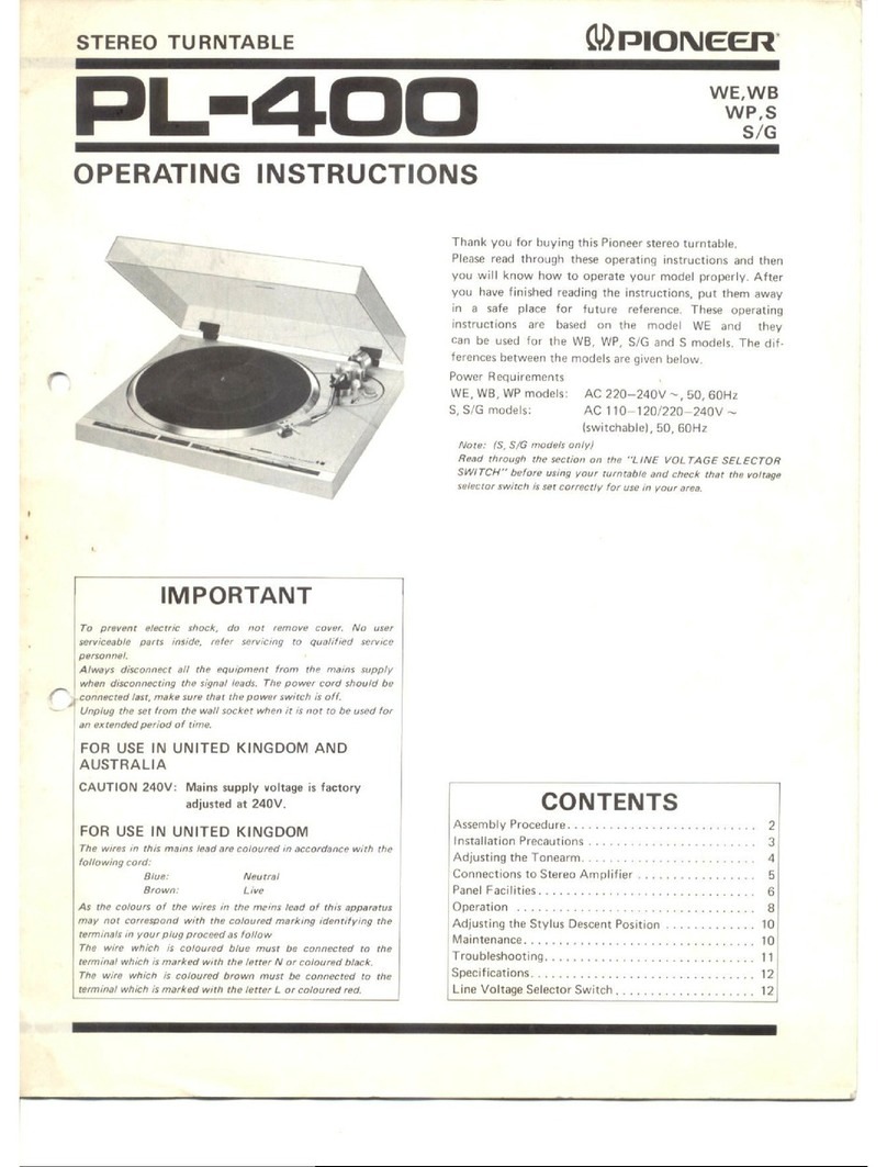
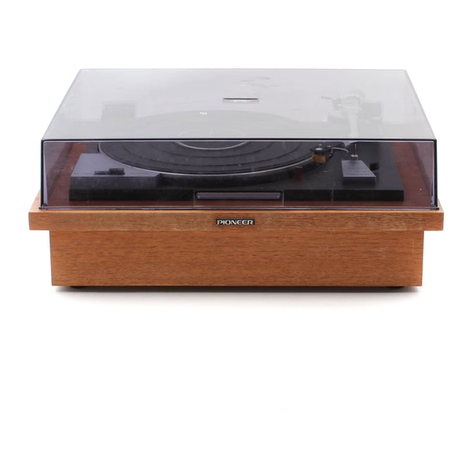
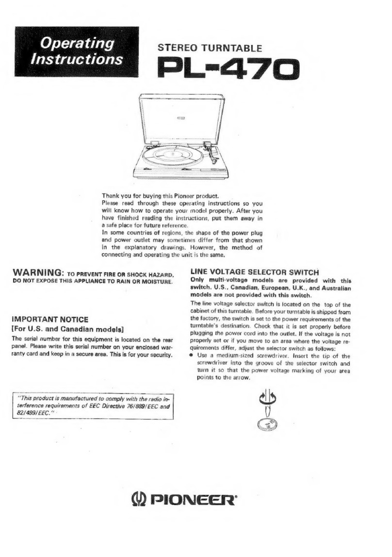
Pioneer PL-100 User manual

Other manuals for PL-100

1

This manual suits for next models

1

Other Pioneer Turntable manuals

Pioneer DEH-P6500 User manual

Pioneer

Pioneer DEH-P6500 User manual

Pioneer PL-5 User manual

Pioneer

Pioneer PL-5 User manual

Pioneer PL-560 User manual

Pioneer

Pioneer PL-560 User manual

Pioneer PL-5 User manual

Pioneer

Pioneer PL-5 User manual

Pioneer PL-3000/HB User manual

Pioneer

Pioneer PL-3000/HB User manual

Pioneer PL-55DX User manual

Pioneer

Pioneer PL-55DX User manual

Pioneer PL-55DX User manual

Pioneer

Pioneer PL-55DX User manual

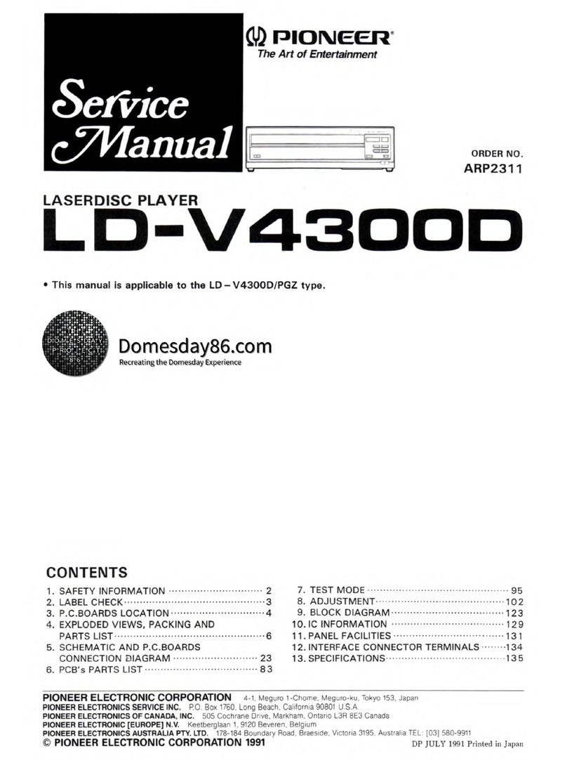
Pioneer LD-V4300D User manual

Pioneer

Pioneer LD-V4300D User manual

Pioneer PL-990 User manual

Pioneer

Pioneer PL-990 User manual
Pioneer C-5600DFV User manual

Pioneer

Pioneer C-5600DFV User manual

Pioneer PL-512 User manual

Pioneer

Pioneer PL-512 User manual

Pioneer PL-514 User manual

Pioneer

Pioneer PL-514 User manual

Pioneer PL-05 User manual

Pioneer

Pioneer PL-05 User manual
Pioneer PL-200 User manual

Pioneer

Pioneer PL-200 User manual

Pioneer PL-500X User manual

Pioneer

Pioneer PL-500X User manual

Pioneer Super Tuner III D DEH-P4800MP User manual

Pioneer

Pioneer Super Tuner III D DEH-P4800MP User manual

Pioneer LD-1100 User manual

Pioneer

Pioneer LD-1100 User manual

Pioneer PL-450 User manual

Pioneer

Pioneer PL-450 User manual

Pioneer PL-61 User manual

Pioneer

Pioneer PL-61 User manual

Pioneer PL-516 KUT User manual

Pioneer

Pioneer PL-516 KUT User manual

Pioneer DEH-P960MP/XN/UC User manual

Pioneer

Pioneer DEH-P960MP/XN/UC User manual

Pioneer CDJ-2000NXS User manual

Pioneer

Pioneer CDJ-2000NXS User manual

Pioneer PL-88F User manual

Pioneer

Pioneer PL-88F User manual

Pioneer PL-A45 User manual

Pioneer

Pioneer PL-A45 User manual

Popular Turntable manuals by other brands

Technics SP-10 MKIIP Service manual

Technics

Technics SP-10 MKIIP Service manual

Trevi Mpv 1745 SD instructions

Trevi

Trevi Mpv 1745 SD instructions

Noblex NXC1039BT Service manual

Noblex

Noblex NXC1039BT Service manual

I.A.V. Piccolo owner's manual

I.A.V.

I.A.V. Piccolo owner's manual

JVC QL-Y5F Instruction book

JVC

JVC QL-Y5F Instruction book

Gemini CDT-05 MKII product manual

Gemini

Gemini CDT-05 MKII product manual

Rotel RP-820 owner's manual

Rotel

Rotel RP-820 owner's manual

Shuman MC-250BT user manual

Shuman

Shuman MC-250BT user manual

Stanton STR8-150 owner's manual

Stanton

Stanton STR8-150 owner's manual

Audio Technica AT-LPW40WN user manual

Audio Technica

Audio Technica AT-LPW40WN user manual

Crosley McQueen CR7011-GY instruction manual

Crosley

Crosley McQueen CR7011-GY instruction manual

auna TT-Classic Plus instruction manual

auna

auna TT-Classic Plus instruction manual

COMO AUDIO Turntable Analog user manual

COMO AUDIO

COMO AUDIO Turntable Analog user manual

Dual 1009 F owner's manual

Dual

Dual 1009 F owner's manual

AXIOMTEK OPS883-H Series Quick installation guide

AXIOMTEK

AXIOMTEK OPS883-H Series Quick installation guide

Vestax PDX-a1 owner's manual

Vestax

Vestax PDX-a1 owner's manual

Denon DP-400 owner's manual

Denon

Denon DP-400 owner's manual

Audio-Techica AT-LP60XBT user manual

Audio-Techica

Audio-Techica AT-LP60XBT user manual

manuals.online logo
manuals.online logoBrands
  • About & Mission
  • Contact us
  • Privacy Policy
  • Terms and Conditions

Copyright 2025 Manuals.Online. All Rights Reserved.

snnnooenarees
Servicec
Manual
STEREO
TURNTABLE
L-1I00
L-IOOX
Y
PIONEER
MODEL
PL-100
COMES
IN
SEVEN
VERSIONS
DISTINGUISHED
AS
FOLLOWS:
ee
Pe
ce
oo
AC
220V
—
240V
United
kingdom
model
(with
cartridge)
AC
220V
—
240V
Oceania
model
(with
cartridge)
AC
110-120/220-240V
(switchable)
General
export
model
(with
cartridge)
©
This
service
manual
is
applicable
to
the
PL-100/WE,
WB,
WP,
PL-100X/WE,
WB.
For
servicing
of
the
other
types,
please
refer
to
the
additional
service
manual.
CONTENTS
:.
“SPECIFICATIONS:
.4.c5:05.06
ee
aes
aoe
ea
3
8.
EXPLODED
VIEWS
2:-
‘PANEL
FACILIMNES®
cia
cies
ee
oe
eee
a
ot
3
BS.
sEXtevor
44
2
o8
bs
Ge
ee
cea
eae
ss
12
3.
DISASSEMBLY
Si2.
“SUuD-DdaNel
2.4%
o.bacbh
SG
Ses
ey
oe
eo
15
3.1
Panel
and
Base
Plate
................
4
9.
SCHEMATIC
DIAGRAM,
P.C.
BOARDS
3.2.
Arm
Base
and
Sub-Panel..............
5
a
DISS
RANE
Apacer
4.
MECHANISM
DESCRIPTION
.............
6
Gt.
TPAC
MASE,
ce
oso
oS
hil
ae
oa
esac
ae
ew
16
5.
ADJUSTMENT
9.2
Schematic
Diagram
............+4-:
17
5.1
Auto-return
Adjustment
...........--
8
9.3.
P.C.
Boards
Connection
Diagram
.......
18
5.2
F.G.
Motor
Adjustment
.............-
8
10;
"PACKING
5
iat
eae
te
hcetacte
teats
19
5.3.
Arm-elevation
Adjustment
............
8
6.
TROUBLE
SHOOTING
6.1
Auto-return
Does
not
Work
...........
9
6.2
Return
is
Fast
(Return
at
1mm
Pitch).....
10
7.
PRECAUTIONS
FOR
REASSEMBLY
7.1.
Areas
That
Require
Lubrication
.......
10
7.2.
Precautions
for
Attachment
of
Parts
and
Reassembly
..........-20.0e00085
11
1.
SPECIFICATIONS
Motor
and
Turntable
Drive
SYStOM)
«26-2
con
8S
eae
Pe
eS
Ge
Sk
Pa
ee
es
Belt-drive
IEQNON
5
oe)
Sos
Sk
he
wal
oe
Se
ws
ie
Og
Wak
a
aes
FG
servo
motor
Turntable
Platter
.....2..
310mm
diam.
aluminum
alloy
die-cast
BOGGS
oso
he
ee
we
Oe
&
Be
Se
Bae
Oat
eS
33-1/3
and
45rpm
Speed
Control
Range..............00
202
ee
eevee
+2%
Wowand
Flutter
..............
Less
than
0.045%
(WRMS)
Signai-to-Noise
Ratio.
............
More
than
70dB
(DIN-B)
(with
Pioneer
cartridge
model
PC-135)
Tonearm
MV
DG
<5
.t5,
(eee
RO
SRS
ee
Static-balance
type,
S-shaped
pipe
arm
Effective
Arm
Length
..........
Re
Nig
cet
ag.
te
aa
ah
os
wy
Rapa
221mm
OVGEINANIO:
.-
&
oa
See
oe
ee
5.
Se
be
ee,
BAS
Bea
S
hee
15.5mm
Usable Cartridge
Weight
............
4g
(min.}
to
9g
(max.)
Subfunctions
Auto-return
mechanism,
Anti-skating
force
control,
Stylus
pressure
direct-readout
counterweight,
Cueing
device,
Strobe
light
,Free
stop
hinges
Semiconductors
Platter/Rubber
platter
mat
Speed
checking
window
a)
SPEED
SELECTOR
BUTTON
45
....
When
this
button
is
depressed,
the
platter
will
rotate
at
45rpm.
Depress
for
playing
45rpm
records,
singles
or
EP’s.
33
....
When
this
button
is
set
to
the
released
position,
the
platter
will
rotate
at
33-1/3rpm.
Release
for
playing
33-1/3rpm
records
like
LP’s.
(2)
SPEED
ADJUSTMENT
KNOB
Turn
this
knob
when
finely
adjusting
the
speed
of
the
platter.
The
speed
of
platter
will
increase
when
the
knob
is
turned
to
the
left
in
the
direction
of
“+:
it
will
de-
crease
when
turned
to
the
right
in
the
direction
of
*—”,
PL-100
Miscellaneous
Power
Requirements:
WE,WB,WP
models
.........
AC
220—240V
~,
50,
60Hz
Power
Consumption
............0...002..0
00-544
4WwW
Dimensions
...............
420(W)
x
96(H)
x
365(D)
mm
16-1/2(W)
x
3-13/16(H)
x
14-3/8(D)
in.
WeIQNE
-6
oo
oie
So
SRR
Se
Re
SE
...
5.2kg/11
Ib
80z
PC-110/I!
Specifications
WV
OO
SS
-n
och
ee
ke
a
eS
Ri
a
ae
a
Moving
magnet
type
SEVIS:
05
ods
ta8:
hs
Bees
ech
etc
at
ad
0.5
mil
diamond
(PN-110/I!)
Output
Voltage.....
3.5mV
(1kHz,
50mm/s
Peak
velocity,
LAT)
Tracking
Force
...............
1.59
to
2.59
(proper
2.2g)
Frequency
Response
..................
15
to
25,
OO0Hz
Recommended
Load...............
50k2
+170
~
300pF
Accessories
EP
AGsptet
6
osc.
6
tg
tng
fh
kk
&
Oho
el
ee
ae
Peeks
1
Operating
Instructions
(French
and
German
furnished
on
model
forWE)
......................
1
NOTE:
Specifications
and
design
subject
to
possible
modification
without
notice,
due
to
improvements.
Anti-skate
knob
3)
ARM-ELEVATION
LEVER
UP(¥):
When
this
fever
is
set
to
this
potion,
the
tonearm
will
rise.
Set
it
to
UP
before
record
play
and
when
you
want
to
stop
ncord
play
while
a
track
is
being
played
or
ashen
you
want
to
change
over
to
a
different
track.
DOWN
(¥):
When
the
lever
is
set
to
this
pojtion
the
tonearm
will
be
lowered.
If
itis
set
to
DOWN
for
record
play,
the
tonearm
will
be
lowered
onto
the
surface
of
the
record,
and
play
will
begin.
3.
DISASSEMBLY
3.1
PANEL
AND
BASE
PLATE
1.
Undo
the
4
screws
@
securing
the
insulator
case.
2.Move
the
tonearm
across
to
the
center,
and
raise
the
panel
a
little.
3.
Disconnect
the
circuit
board
connector
(2-Pin).
Base
plate
Float
spring
(GRE)
Float
spring
_§
Insulator
case
_&
“
(VLT)
°
&
0
Float
spring
Damper
rubber
!
I
Float
spring
(BLK)
S-
(VLT)
:
~
0
Fig.
3-1
Remove
the
panel
and
base
plate
EME
HR
EEA
REE,
3.2
ARM
BASE
AND
SUB-PANEL
1.
Undo
the
5
screws
@
securing
the
arm
base.
2.
Undo
the
2
screws
@
securing
the
sub-panel.
3.
Undo
the
3
screws
©
securing
the
center
shaft.
Arm
base
Tonearm
assy
Base
plate
Fig.
3-2
Remove
the
arm
base
and
sub-panel
PL-100
4.
MECHANISM
DESCRIPTION
PL-100
MECHANISM
OPERATING
The
PL-100
is
equipped
with
auto-return
only.
Fig.
4-1
shows
the
PL-100
in
the
stationary
state
with
the
tonearm
back
in
the
arm
rest.
Gear
A
Ae
es
a
>
UR
TAR
Gre
cs
¢3
=
&,
e
Fig.
4-1
Mechanical
parts
name
*
Start
of
Play
Lever
A
1.
When
the
tonearm
is
moved
across
to
the
disc,
the
PU
plate
located
below
in
the
arm
base
is
also
moved.
2.
Lever
A
is
moved
over
by
pin
A
connected
to
this
PU
plate,
resulting
in
lever
B
being
un-
locked
(Fig.
4-3).
3.
At
the
same
time
that
lever
B
is
unlocked,
the
microswitch
is
turned
on
(power
on),
and
the
motor
commences
to
rotate
(Fig. 4-3).
Pin
A
Microswitch
Fig.
4-3
Start
of
play
*
AUTO-RETURN
DETECTION
1.When
the
stylus
nears
the
center
shaft,
pin
B
contacts
plate
A
(Fig. 4-4).
2.
Plate
A
pushes
plate
C
by
an
amount
directly
proportional
to
the
amount
of
movement
of
ee,
He
the
tonearm
(Fig.
4-5).
Figen
erent
3.Plate
D
atop
plate
C
is
moved
toward
gear
B
by
the
movement
of
plate
C.
pant
Ricithe
ARERR,
Fig.
4-5
Auto-return
detection
2
Gear
B
Plate
D
Dav.
W/
Ce
»
CE
Fig.
4-6
Auto-return
detection
3
Gear
B
feces
q|
Gear
A
Yi.
>.
Plate
D
ya
/
Del
SA
Fig.
4-7
Auto-return
detection
4
PL-100
4.The
front
end
of
plate
D
moves
approximately
O.lmm
when
the
stylus
is
advanced
1mm
toward
the
center
shaft
by
one
revolution
of
the
record.
5.The
tooth
of
gear
B
has
the
dimensional
dif-
ference
shown
in
Fig.
4-6.
6.Plate
D
is
pushed
back
by
this
dimensional
difference
at
a
stylus
movement
of
within
1mm
per
revolution
of
the
record.
7.When
the
stylus
enters
the
lead-out
groove
in
the
record
at
the
end
of
the
performance,
it
is
moved
4mm
toward
the
center
shaft
by
one
revolution
of
the
record.
8.The
end
of
plate
D
contacts
the
protruding
section
of
gear
B
(Fig.
4-7).
9.
Gear
B
and
gear
A
are
engaged,
and
gear
A
is
turned
by
rotation
of
the
turntable.
*
AUTO-RETURN
1.
Gear
A
and
B
are
engaged
each
other
by
the
auto-return
detector
and
gear
A
consequently
is
turned
in
the
counter-clockwise
direction.
2.
Plate
B
is
then
shifted
across
towards
the
tone-
arm
due
to
the
groove
in
the
underneath
of
gear
A.
3.The
edge
of
plate
B
pushes
against
lever
C
to
force
the
arm
elevation
upwards.
4.
Plate
B
continues
to
shift
across
to
push-
against
pin
B
on
the
PU
plate,
thereby
returning
the
tonearm
back
to
the
arm
rest.
o.
At
this
stage
plate
B
commences
to
return
to-
ward
the
center
shaft
guided
by
the
groove
in
gear
A.
Gear
B
Gear
A
ig
eet
RRR
Fig.
4-8
Auto-return
1
6.
When
the
edge
of
plate
B
separates
frorm
lever
C,
the
arm
elevation
is
lowered
to
drop
the
tonearm
back
into
the
arm
rest.
7.And
at
the
same
time
that
the
tonearm
is
returned
to
the
arm
rest,
pin
A
returns
Jever
A
back
to
the
stationary
state.
8.Plate
B
continues
to
move
toward
the
center
shaft
and
pushes
against
pin
C
on
lever
B.
Lever
B
thus
switches
the
microswitch
off
(power
off),
and
is
then
locked
by
lever
A,
thereby
bringing
a
complete
operation
cycle
to
an
end.
5.
ADJUSTMENT
9.1
AUTO-RETURN
ADJUSTMENT
1.Turn
the
auto
return
adjustment
screw
full
around
clockwise.
2.
Move
the
tonearm
right
across
toward
the
center.
3.When
the
auto
return
adjustment
screw
is
turned
back
a
little
at
a
time
counter
clockwise,
the
tonearm
will
commence
to
return
to
the
outer
circumference.
4.Stop
turning
the
adjustment
screw
once
the
stylus
tip
is
383mm
away
from
the
center
shaft.
5.
Once
the
above
adjustment
procedure
has
been
completed
check
that
the
tonearm
returns
auto-
matically
as
designed.
5.2
F.G.
MOTOR
ADJUSTMENT
1.
Turn
the
power
on
and
start
the
turntable
plat-
ter
rotating.
2.
Turn
the
speed
adjustment
knob
around
to
the
mechanically
center
position.
3.
Adjust
VR2
and
VR83
in
the
motor
assembly
so
that
the
stroboscope
appears
to
be
stationary.
Again
this
adjustment
is
performed
from
below.
4.
Adjust
VR2
for
33rpm
speed,
and
VR3
for
45rpm.
|
5.3
ARM-ELEVATION
ADJUSTMENT
To
proceed
with
the
elevation
sheet
height
adjustment,
insert
the
hexagonal
wrench
(for
3
mm)
into
the
hole
at
the
front
of
the
EV
sheet
and
rotate
it
clockwise
to
reduce
the
height
and
coun-
ter-clockwise
to
increase
the
height.
The
height
of
the
stylus
tip
from
the
record
surface
is
7
+2
mm.
Fig.
4-9
Auto-return
detection
2
_
river
3
wy
Fig.
5-2
Motor
adjustment
Elevation
sheet
Fig.
5-3
Arm-elevation
adjustment
PL-100
6.
TROUBLE
SHOOTING
Use
the
following
directions
to
find
the
cause
of
each
type
of
breakdown.
Improperly
adjusted
units
should
be
completely
readjusted.
6-1
AUTO-RETURN
DOES
NOT
WORK
START
Change
in
starting
position
adjust-
ment.
Plate
D
does
not
follow
the
plate
C
After
starting,
incomplete
reset
of
the
plate
C.
See
@
Too
much
grease
between
the
plate
C
and
the
gear
A.
The
curved
section
of
the
plate
C
is
deformed.
Inner
diameter
of
the
plate
D
bear-
ing
is
small.
The
inner
areas
of
records
can
not
be
tracked.
Protrusions
on
the
caulk
section
of
the
plate
D
bearing.
Arm
lead
wire
is
caught
on
some-
thing.
Not
enough
grease
between
the
plate
D
and
plate
C.
PU
cord
is
touching
the
PU
plate.
Looseness
in
the
PU
plate
attach-
ment.
PU
plate
is
touching
the
leaf
spring
(plate
D)
Operation
of
the
plate
A
is
not
smooth.
Procedure
for
Dealing
with
item
@
After
performing
the
return
operation,
if
the
curved
section
of
the
plate
C
and
curved
section
of
the
plate
D
are
not
in
contact
with
surfaces
and
(B)
respectively
of
the
cam,
reset
will
be
|
select
incomplete
and
the
starting
position
will
be
late.
Gear
A
0.5mm
As
a
result,
the
return
function
may
not
operate
at
times.
In
this
case,
bend
the
plate
C
C)
so
that
Fig.
1-6
Incomplete
plate
D
and
plate
C.
dimension
A
is
0.5mm
or
larger.
6.2
RETURN
IS
FAST
(RETURN
AT
1mm
PITCH)
Protrusions
on
the
pinion
gear
sec-
tion.
See
@
Procedure
for
Dealing
with
Item
@
If
there
are
rough
areas
of
plastic
protruding
from
the
@)
section
of
the
protruding
section
of
the
pinion
gear,
the
return
function
may
operate
at
a
pitch
of
only
1mm.
In
this
case,
remove
the
plastic
protrusions
completely
(Fig.
6-2).
Gear
B
(pinion
gear)
protruding
section
Fig.
6-2
Elimination
of
pinion
gear
protrusions.
7.
PRECAUTIONS
FOR
REASSEMBLY
Follow
these
directions
and
precautions
when
reassembling
a
unit
after
completing
repairs.
Be
sure
to
lubricate
as
required,
make
no
mistakes
when
attaching
parts,
and
avoid
all
other
careless
mistakes
that
may
be
the
cause
of
trouble
later
on.
7.1
AREAS
THAT
REQUIRE
LUBRICATION
NOTE:
Types
of
lubricants
and
areas
where
they
are
used
are
listed
in
table
1.
Table
1
Type
of
Oil
Areas
used
|
Silicon
Oil
#50000
raising
shaft
GYA-008
all
other
areas
Lubrication
points
are
specified
for
oils
other
than
GYA-008.
Never
use
a
different
type
of
oil.
®
Cam
Section
Apply
oil
to
the
heart-shaped
grooved
section
(rear
side
of
the
cam)
and
lock
plate
sliding
section
in
order
to
minimize
wear
on
the
sliding
section
and
the
burden
on
the
mechanism.
@
Driving
Plate
Assembly
Decrease
the
burden
on
the
mechanism
and
the
wear
on
the
sliding
section.
sides,
top,
and
bottom
surfaces
(sliding
section
of
auto-stop
mechanism)
sides
surface
(sliding
section
of
auto-stop
mechanism)
top
and
side
(sliding
section
of
auto-stop
mechanism)
EV
cam
side
surface
(sliding
section
of
elevation
cam)
Fig.
7-1
Driving
panel
assembly
section
Switch
Locker
Section
10
®
Switch
Locker
Section
Apply
oil
to
the
switch locker
(opening)
and
sub-panel
base
sliding
section
to
decrease
the
burden
on
the
mechanism.
When
applying
oil
to
the
opening
(shaft
hole),
do
not
apply
any
oil
2—3mm
from
the
bottom
surface.
If
oil
is
applied
2—3mm
within
the
bottom
surface,
it
may
come
out
the
bottom
and
go
between
the
switch
lever
and
sub-panel
base
causing
the
switch
lever
to
operate
ineffectively.
switch
locker
Fig.
7-2
Switch
locker
section
e
EV
Lever
Unit
Section
Apply
oil
to
the
sliding
sections
of
leaf
spring
(A)
and
EV
lever
unit
to
decrease
the
burden
on
the
mechanism.
leaf
spring
(A)
sliding
section
EV
lever
unit
EV
lever
unit
sliding
section
Fig.
7-3
EV
lever
unit
section