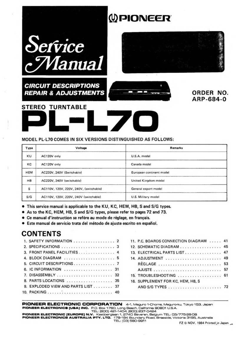
Pioneer PL-500X User manual

$eftice nual
STEREO
TURNTABLE
PLIE OOX
(DrrroNeER'

MODELPL-5OOX
COMESINTWOVERSIONS
DISTINGUISHEDASFOLLOWS:
Type Voltag€ R€merk3
HET 22OV and 24OV (Switchable) Europemodel (Without cartridge)
HBT 22OV and 24OV (Switchable) United Kingdom model (Without carrridgo)
CONTENTS
1.
SPEC|F|CAT|ONS
..... ........ 3
2. PANELFACILITIES. 4
3. DISASSEMBLY
3.1 Cabinet.
. 6
3.2 Tonearm 7
4. ADJUSTMENTS
4.1 D.D.Motor
OperationAdjustment I
4.2 MechanismAdjustments. 9
5. PACKING
6. EXPLODED
VIEWSANO PARTSLIST
6.1 Cabinet.. .......11
0.2 Subpanel .........14
6.3 D.D.Motor... ...........16
7.
SCHEMATICDTAGRAM .........17
8. P.C.
BOARDCONNECTION
DIAGRAM
8.1 Parts
ListofP.C.Board
Assembly
.......21
For description
of the D. D. motor, refer to the
PL-630
service
manual
(ART-314)
andfor full auto
mechanism,
refer to the PL-3000service
manual
(ART-350).

PL-5ClC'x
1.
SPECIFICATIONS
Motor andTurntable
Driv€System .. Direct-drive
Motor......... .. ..
...
Ouartz
PLLHallmotor
Turntable
Platter . .. . . . . ..33omm
dism.atuminumalloy
die-c6st
lvloment
ol lnertie 3ookg{m' {including
plaltermatl
Speeds,......... ... 331/3and4srpm
WowandFlutter ....... Lessthsn0.025%
(WRMS)
Signsl-to-NoisoRatio. ..... Morerhan
75dB
(DlN-Bl
(wilh Pioneer
cartridge
mod€l
PC-200)
Rotational Characteristica
Build-upTime . . Wirhin120"rotationar331/3rpm
Spoed
Deviation.. ... Lessthan0.002%
Speedvs.LoadCharacteristics
.......... Srabteupto
150
grams
dragload
SpeedDrift . .. . . LessrhanO.OOOOS%/h
at33-1/3rpm
Lessthan0.00o03%/d€greetemp.ch6ngeat 33-1/3rpm
Transistors.
Diodes........
Hall Elements
.
Miscellaneous
PowerRequirements
Pow€r
Consumption
Dimensions
Weight
Accessories
........3
........3
. ......3
. 22O|24OV
- (switchable),
s0,60H,
......10w
...... 440(W)x'140{H}x388(D}mrn
17-15/16(W)x
s-1/2{H)xl5-1/4(D)in.
. .9.1ks/201b
rA
EPAdapter
Screwdriver
Carlrjdgemounting parts
Carlridgemounting screws.
Cartridgemountrng
nuts .
C6rtridgemountingwashers
.
Operating
Instructions
(French
and Germanfurnished
on
rnodels
for HET)
NOTE:
.1
.1
1
Specifications and design subiect to po$ibte modification without
notice. clue to improvements.
Subfunclions
Full auto mechanism, Anti-skating force controf, Stylus pressure
direct-readout
counterweight,Cueingdevice,
Srrobe
light, Free
srop
hrnges
Semiconductors
lCs
)., v
LINE
VOLTAGE
SELECTOR
SWITCH
Thelinevoltageselector
switch islocatedon thetop surface
of the cabinetof this turntable,Before
your turntableis
shipped
from the factory, the switch issetto the powerre-
quirements
of the turntable'sdestination,
checkthat it is
s€t
properly
before
plugging
the
power
cordintotheoutlet.
lf thevoltageisnot properly
s€tor if youmoveto anarea
where the voltagerequirementsdiffer. adjust the selector
switchasfollows:
1. Oisconnectthe
Dowercord,
2. Provide
yourself
with amedium-sized
screwdriver.Insert
the tip of the screwdriver
into thegroove
of the selector
switchandturn it sothat the power
voltagemarking
of
your area
points
to thewhite markby thearrowonthe
label.
Scr€wdriver
2.
PANELFACILITIES
f--

rE\
O srnnr BUTToN
When
thisbuttonisdepressed,
thepower
isturnedonto
the turntable,the strobelight comes
on andthe platter
startsto rotate.with the REcoRD slzE SELECToR
setat oneof thepositions
- 30,25,or I7 - thetonearm
moves
automatically
to therecorddisc
as
the
platter
starts
rotating,thus startingrecord play
@ REPEAT
BUTToN
Push
thisbuttonwhen
you wantto listen
to thesamere-
cord
again.
Press
thebuttononce
moreto release.
NOTE:
All you have to do fot repeat play is to prcss the REqEAT button.
Therc is no need to push the START and C\JT button again.
@ CUT
BUTToN
lf thisbutton isdepressedwhil€
therecord
is
playing,
the
tonearm
automaticallyreturns
to the arm rest.and the
power
to theturntablewill be
cut
off.
@ RECORD
sIzE SELECToR
Thisselectorselects
thesizeof the recordfor automatic
play
and
alsoselectsmanual
play.
7"17
. . . . For
the
automatic
play
of 17cm
(7-inch)
LP
and
EP
records.
10"25.
. -. For
theautomatic
play
of25cm
{1o-inch)
LPrecords.
12"30.
. .. For
theautomatic
play
of30cm
(j2-inch)
LP
records.
MANUAL.. For
themanual
play
of records.
NOTE:
The toneam will not be actuated when the RECORD SIZE
SELECTOR is at the MANUAL posiaion fot play, even if the
START button and tha REPEAT button arepushd.
@ SPeeo
SELECToR
BUTToN
45 . . . . . When
thisbuttonisdepressed,
the
platter
will
rotateat 45rpm. Depressfor playing
45rpm
records,
singlesor EP's.
33 . . , . . When
thisbutton
issetto therelease
position,
the platter
will rotate
at 33-1/3rpm.
Release
for playing
33-1/3rpmrecords
likeLp,s.
@ STROBE
LIGHT
Thislight
comes
on when
thetonearm
moves
awavfrom
the arm resttowardthe platter.
lt irradiates
thestrobo-
scope
around
theoutside
of the
platter.
O TONEARM
This tonearmis designed
to apply the correct
tracking
force
to thecartridge
andto keep
thisforce
atthe
precjse
levelfor faithful
tracking
of therecord
grooves.
PL-E'clC'X
@ARM-ELEVATION
LEVER
Thislevercontrols
theascent
anddescent
of the
tonearm.
UP
{!) ..... Thetonearm
rises.
OOWN
(l) . . The
tonearmdescends
gently.
Set to this position
for auto play,auto
repeatand
otherautomaticoperations.
NOTE:
When the ARM ELEVATION lever is set to the UP position
for automatic play, the toneam will move over as fal as the
lead-in groove on the record but it will not descend and the
rccord will therefore not be played.
@ ANTI.SKATE
KNoB
This
knob is
usedto cancel
out theharmful
skating
force
whichis
geneiated
duringrecord
play.
For further details, see "ANTI-SKATING ADJUST-
I\4E
NT
".
@ nnru REST/CLAMPER
The arm rest
supportsthe tonearmwhen
it isnot being
used.
Setthetonearmonitsrestwhenit isnot playing
re-
cords.
Clampit into position
if you don't have
anyim-
mediate
plans
to play
records.
O PLATTER/RUBBER
PLATTER
MAT
Whenthe tonearmismoved
and
power
issuppliedto the
turntable,the platter
will startrotating
atthesetrotation
speed.The rubber
platter
mat stabilizestherecordsand
alsoabsorbsexternalvibration.
@ DUST
coVER
Keep
thisclosedunless
operatingthecontrols
ortonearm,
or changingover records.
Thisservesto keep
dust
from
adhering
to the recordsduringrecord
play.When
fully
openedand pulled
straightup, thisdust
covercanbere-
moved
fromthecabinet.
r
5

3.DISASSEMBLY
3.1 CABINET
(See
Fig.3-ll
1. Removethe dust cover.
2. Undo the 4 screwssecuringthe top cover.
3. Undo the 4 screwslocated in the rubber feet.
4. Move the tonearm over towards the center
shaft asshown in the diagram.
5. Disconnect the connectors when lifting off the
cabinet.
Cabinetsecuringscrews I
u
I
uFis.3-1

A
3.2 TONEARM
1. Undo the 4 screws securing the arm baseand
the sub-panel(see
Fig. 3-2).
2. Undo the 2 screwssecuringthe arm base
to the
sub-panel(see
Fig.3-2).
3. Disconnect the tonearm lead wires from the
PU board(see
Fig.3-2).
Note that some of the lead wires have been
soldered to the PU board, and must be dis-
connected with care.
4. Loosen the setscrews
with a hexagonalwrench
to remove the PU plate under the arm base
(see
Fig.
3-3).
5. Undo the screw securing the tonearm to the
arm base(see
Fig. 3-3)
f tg. J-z
PL-5C'clx
Arm basesecu
rrg. J-J

4. ADJUSTMENTS
4.1 D.D
MOTOR
OPERATIONADJUSTMENT
l. Rotate the tumtable platter.
2. Connect
a dual-image
oscilloscope
(or synchro-
scope)to the TP3 and Q2 terminals of ttre cir-
cuit board ass'y.
3. Adjust VR1 (for 33-1/3 rpm) and VR2 (for
45rpm) on the circuit board ass'yin order to
bring the rising edgeof the TPb terminal wave-
form within the width of the TP6 terminal
waveform asshown in Fig. 4-2.
Fiq.4-1
02 (tc=pA2oo4) Fis.
4-2
,
a
TP3
1'

Y
'J 4.2 MECHANISM
ADJUSTMENTS
Prior to commencing any adjustments, check
that the PU plate shaft moves along the center axis
of the slot in the sub-panelasshown in Fie. 4-4.
Fis.44
o Tonearm lowering position
Tonearm lowering position is adjusted by tum-
ing an adjustment screw located in the hole at the
baseof the tonearm (see
Fig. 4-5).
Tum the screw clockwise to move the lowering
position inwards.
Tum the screw counterclockwise to move the
lowering position outwards.
This adjustment may be simplified by using a
test record .
Fis.4-6
o Tonearm misoperation
If the tonearm should happen to stop midway
during the lead-in operation, adjust the nut shown
in Fig.4-7.
This nut should be neither too tight, nor too loo6e.
Fis.4-7
r Short switch
The short switch gap shouldbe 0.5mm during
record play. This gap may be adjusted by the
screwshown in Fig. 4-8 below.
Screw
driver
Adjustingscrew
Shortswitch
Rotatory
cam
PU
plate
screw
r
Lowering
position
toofarout dt-
IJ
t-
oFis.4-5
r Auto-return position
1. If the tonearm retums too earlv. screw the PU
plate screwoutwards (see
Fig. 4-6).
2. If the tonearm retums too slow. screw the PU
plate screwinwards.
Lowering
position
tootarin
g
i)
Fig.
4-8

PL-5ClC'X
5. PACKING
Parts
List
Key No. PartNo. Doscription
6.
7.
8.
9.
10.
1. PHA-077
2. H56-603
3. PBA-079
4. PRW-O38
5. PHG-369
PHC-069
N93.603
KEX,OO2
PRB.135
PRD{46
11, PEA{32
12. 822426
't3. PXA-720
14, PXA€76
15. PXB-125
Cautionlabel
Cover
45 adaptor
Driver
operating instructions
(English
)
Operating
instructions
(French/German)
Rubber mat ass€mbly
H€adshellassembly
Csrtridge
mounting screwassembly

6.EXPLODED
VIEWSAND PARTS
LIST
6.1 CABINET
#
V
56

*#e
fi:,,N.F:
[6? 1b ,t
at'
'/ 84
./A
rar
@
'o\4P - _""-"9:i
^&
@
g
&
H
tl
d,

PL-5ClC,x
.r PARTSLIST
OFCABINET NO?ES.
. Parls uithout part number cannol besupplied.
K6y No. P.rl No.
o The I marh found on
safely loclor ol the part.
desiEnation.
Doscription
some component parts ind.icotes
the importance of the
Therefore, uhen replocing, be sure to use
parts of id.entical
Key No. Part No. Description
1. PEA-032
2. PNR-089
4.
5. PNX-080
6. PAC-O24
7.
8. ........
10.
11.
12.
13.
14- PNW-473
15. PAG-001
16. PNW-472
17.
r8. PNX-078
A 20. PTr-093
21.
, 22.
24.
27. PXB-I03
30.
Rubbermalassembly
Turntable
platter
TapritoPscrew
3x8
Cover
Panel
Push
button
PSA
3x5
54. XWM{33
55.
36. PAG020
37. PSF-o12
39. PNV-014
40.
41. PEC-o5'|
42. PEC-o51
43.
44. PDE-044
45, PDG-O21
(HEl
POG_022
(HB)
46.
47. PNW-475
ra.
49. PNW-474
50. P8H-213
Angle
TapriteP
screw3x10
Speedselector
assembly
Lens
Mirror
Holder
TaptiteP
screw3x10
Neon
lampholder
TaptiteP
screw3x'l0
Power
lransformer
TaptitePscrew4x10
Spacer
Output
terminal
PSA
3x12
EW3
PSA
3x5
Sub
panel
assembly
Push
buttonunir
TaptiteP
screw3xl0
Buttonbase
Pushbutton
Startbutton
PSA
3x15
Oust
cover
PSF
3x8
Strain
relief
Strainrelief
Angle
Outputcord
ACpower
cord
Selectorlever
Selectorcam
Spring
Steelball5/32"
Selector
baseunit
TaptitePscr€w3x10
Circuitbosrd
TaptiteP
screw
3x10
Taptitescrew4x8
Hinge
assembly
He€dahell
assembly
Tonearm
assembly
Weight
assombly
Arm rest
assembly
Elevation
sheet
ASknob
Hexagon
socketheadless
iel screw4x8
Plastic
screw3x8
ASspring
washer
AScam
Taptit€screw
3x6
Shatr
EV
spring
EW4
EVlever
unil
EV
spring
ASlever
ASspring
Eiaslever
PU
plare
assembly
PU
plate
Hexagon
socket
headless
setscrew4x6
EW2
(SUS)
EW3
(SUS)
ASwash€r
Adjustshaft
Spring
Plastic
screw3xl2
Spring
PSA
4x10
D.D.
motor
Bas€
DampercushionA
Holder
Ring
56.
57.
59.
r
PAC-O24
61. PXA-720
62. PXB-002
63. PNW-577
64. PAC-026
65.
67.
68. PNX-088
69. PBEOT
2
70, PNW-379
71.
72. PLA-396
13. PBH-201
74.
15- PXT-301
76. PBK430
11.
78. PNC-O68
79. PBA-085
80. PBH-250
8t. PNB460
42.
83. PXB-001
83-1.
83,2.
83-3.
83-4.
83-5. PN8-224
83-6. PNB-519
83-7. PXT-l09
83-8. PXT-201
83-9. PBH-045
83,10.
83,11.PBH-193
84.
85. PXBOl0
86.
47. PEB-102
88. PNW,484
89. PNW-375
90. PYY-024
f
/.
{-.
It 31.
34.
A
A
A
)

Key No, Part No. Description Key No. Ptrt No. Dercription
NO?ES:
o Partswithout part number cannot besupplied..
64
,%
61
#
91. PBA-096
92. PBH-I97
93. PBH-I96
94. PBH-198
95. PBH-198
96. PNW-577
97. PNT-516
98.
6.2 SUB
PANEL
Screw
Spring
Spring
Spring
Spring
EV sheet
Sheet
cushion
FW3
16
17
18
19
99.
100. PAC-023
101. xwx-01
3
102. PXT-314
103. PBK-027
104. PXT-296
105. PBF-005
Aroo. PEc-os2
FW3
Knob
Switch assembly
Actuator D
Actuator B
Actuator A
AS knob washer
Insulator
s
,l
&.'
W,,,
q
&;ss
t
{
t
52-
50
51
3r,
34
&
o)+.--s8
\\hxr
4t>)==57
@=-se
22
25
44 4'r
42
-41
14
*-.u
#*,

PARTS
LISTOFSUB
PANEL
FL-5ClC,x
NO?'Sr
. Parts without part number cannot be supptied.
Koy No. Part No. Oo3cription Koy No. PartNo. De.cription
,a
1.
2. PXT
-297
3.
4. N5t-786
6. PXT-219
1.
8.
A 9. PX
M-o8o
10.
A rr. PEc{52
A rz. PsF{og
A rs. PsF{og
14. PXT-124
16. PBK-029
11.
18. KNA-101
19.
20.
21.
22. PNB-I
12
23.
24.
25. P8H-096
26.
21. PNW-476
28.
30.
31. KSN-001
32.
33.
34. PBH,194
35. PNW{77
36.
38. PNB-s19
39.
40.
41. PNB-519
42.
43. PXT-310
44.
45.
46.
47. 833609
48. PXT-308
49. PAKO06
50. PBF{03
51. PXT-300
52. KLA-I59
53.
54.
56.
57. PXT.3r
2
58. 833-635
59.
60. PLA-404
61. PBH-097
62. PNW-490
63. PNW-478
64. PBH-200
6s. PBH-l95
66.
67.
68.
69.
70.
Startleverunit
Nut
EW2
Stopper
unit
PM 2.6x6
Stopper
Taptite screw 3x8
Stopper
rubberunit
Polyethylene
washer4.10x0.25t
Trptit€ screw 3x5
Timing motor
Sub panel
unit
lnsulalor
Microswitch
Microswilch
Polyethylene
washer4.1Oxo.25t
Polyethylene
washer4.10x0.25t
EW3
Lever
EW3
Taptite screw
2x2.6
Cam
EW2
Lock lever
spring
PM2.6x8
Collar
Spring
EV cam
EV cam
spring
EV lever
spring
EW3
PSA3x25
Connector
assembly
f
f.
rL
Switch
FW2.6
PM2.6x5
Spring
Selector
plate
EW3
EW3
EW3
EW3
Spring
Rotor
unir
Spring
I
15

F
,\
7
II
,--@l
/-{
qr'-
A
g/-
tit
Y/
PSA3XlO
-
a
Fey No. Part No.
6.3 D.D.
MOTOR
Parts
List
Pllz.6x
Description
Pl!2.6xr0
Key No.
;'
I
t'
13
14
NO?ES:
o Partswithout part number cannot besupplied.
Part No. Description
l.
2. PEF-001
3.
4. PTL-003
5.
6.
7.
8. PHEO3OFA
9.
10.
Rotor assembly
Steel
ball
Speed
detector assembly
Core
unit
Positionaldetector
assembly
P.
CB
Base
Hall
element
Cordfixer
Angle
11.
12. MNT-001
13. MNW-001
14.
15. PDE-O38
16.
Base
Ring
Plate
Cover
Connector assembly
Taptite screw 3x8
16

7. SCHEMATIC
DIAGRAM
arJytrzzl
xwtra
-O33
CONTROL
10n6
+Q
I PD1003 Q2 PA2004
x- +Rl
rauHa.7
l't -_vvl
c2 R2
56p 1k
X-TAL
PSS-OO3
cI1 0.47/35
to
(r
.t!
oo
u>
uo
()
v,
a
f,
I
xc12 0.t8
U-
. Ld<>
Hfid
!
OI
G
dH
p>
l!O E,
lr,
F
E
<9
ILZ
o
(J
t
uJ|r)
zu,
lrJ (9
G<
lrj F
|!J
lrJ O
G>
lR3
Lloo
)
)
c9
o.o4
t|
|l
c8
100
/6.3
(NP)
SE
\I
dP
i; N
e
|!
rf
Er
EO
I(9
3E
AC POWER CORD
R02
II
-J
TP3 TP2
TPl
l--
ls5
I SPEED
D1 SI
RBAlO(Pcx-oro)
----t
or lN4OO5
PSG-Or5
swtTcH
s5
Ass'y XWX-
013
Q4
2SC945-Pr
o5
2sD234
DZ YtZ-Z$r
Q6 Rt13 4
Q6 2SC
+
tc23
100
/35
AC POWER
CORD
LINE VOLTAGE
ECTOR
A p66'l-oztrxo
sra
START
/ REPEAT
PSF-ol2
52A
CUT(STOP)
PSF-Or2
R14
820
BRN\
r-- --
lo* s4 ^ s4 MtcRo
(
sroP) i
A PsF-ooe i
r----
1
51
888

l--
I
H'lrr fl3
PHE - 3O3FA
FL-5OCIX
,BLK
/WHT i/l
MoroR ass'y I
PxB
-olo I
Rr6
8.2
k
(2w)
o6 R13 4.7k
Q6 2SC1279-S
1. RES
ISTO
RS:
f
ndicated in Q
, t/oW,
t5% toleranceunless
otherwise noted k : kCl,
M : Ma, (F) : !1o/o,
(G) : t2o/o,
(K) :t 10%
tolerance
2.
CAPACITORS:
Indicatedin capacity (!F)/voltage (V) unless
otherwise
notedp : pF
Indication without voltage is 50V except electrolytic capacitor.
3.VOLTAGE,
CURRENT:
U :DCvoltage
(V) at no input signal
fr mA: DCcurrentat no input signal
4.
OTHE
RS:
@ :
Adjusting
point.
The A mark found on some component pafts indicates
the im-
portance of the safety factor of the part. Therefore,when replacing,
besure
to use
parts
of identical
designation.
SWITCHES:
SI : START/
REPEAT ON
- OFF
32 : CUT(STOP) ON
- OFF
53 : MICRCXSTART/REPEAT)
ON
- OFF
54: MICRO(STOP) ON- OFF
55 : SPEEDSELECTOR 331/3rp 45rpm
58 : LINE
VOLTAGE
551E9198'UG.24OV
The
underlined
indicates
the
switcfr
positi6n-
This
is
thebasic
schematic
diagram,
but theactual
circuit
mayvary
dueto improvements
in
design.
NE-
WHT
NEON
PEL-O39
R11
680
(1w) +c20.
xlo
/35
Q3 PA
2005
R10
2.2U/2W) (r
lr.l
E
o
=zo
lrl -
E5
\ trj
Otr
la z
OJ
tr<
'-2
8e
cu)
3&
-1::l I
<&
(lo
Et
()(r
l!
9tc
i3E
OFJ
>an
g lfoot
(L
o
F
@
I
Y
()(9
z
=
F
H3 Tooo'
N
TL
L'
z
z9
ae:2
(lFur
u<>
>Ftrl
trtC)G
(rGO.
G
P
I
o
z
VR1 SPEED
ADJ (33Tl3) PCP-OI2
VRz SPEEO ADJ (45) PC
P
- O3I
Q4
zSC945-Por
Q
Q5
250234
02 wz-280
TE
lrJ
F
E
> t^l
\>
ILZ
o
o
rff
:o
IO
HE
A
1E|

8. P.C.BOARD
CONNECTION
DIAGRAM CUT
(ST(
SUBPANEL
Ass'yPXB-I03
I- - ruorbn-l
CONTROL
Ass'Y
XWM€33
MOTOR
Ass'yPXB{10
S'IIVITCH
Ass'y
XWX-01
3

START
REPEAT
lss'yPXB-I03
[-or.onl
I lvI
0L As'y XWM{33
l-
t-----l
Table of contents
Other Pioneer Turntable manuals

Pioneer
Pioneer PL-112D User manual

Pioneer
Pioneer PL-A35 User manual

Pioneer
Pioneer PL-L50 User manual

Pioneer
Pioneer PL-100 User manual

Pioneer
Pioneer PL-L70 User manual

Pioneer
Pioneer PL-41 User manual

Pioneer
Pioneer PL-990 User manual

Pioneer
Pioneer Super Tuner III D DEH-P4800MP User manual

Pioneer
Pioneer PL-570 User manual

Pioneer
Pioneer PL-470 User manual

Pioneer
Pioneer pl-930 User manual

Pioneer
Pioneer DEH-P960MP/XN/UC User manual

Pioneer
Pioneer PL-990 User manual

Pioneer
Pioneer PL-600 User manual

Pioneer
Pioneer PL-516 KUT User manual

Pioneer
Pioneer PL-71 User manual

Pioneer
Pioneer PL-L1000 User manual

Pioneer
Pioneer PL-520 User manual

Pioneer
Pioneer PL-530 User manual

Pioneer
Pioneer PL-6 User manual