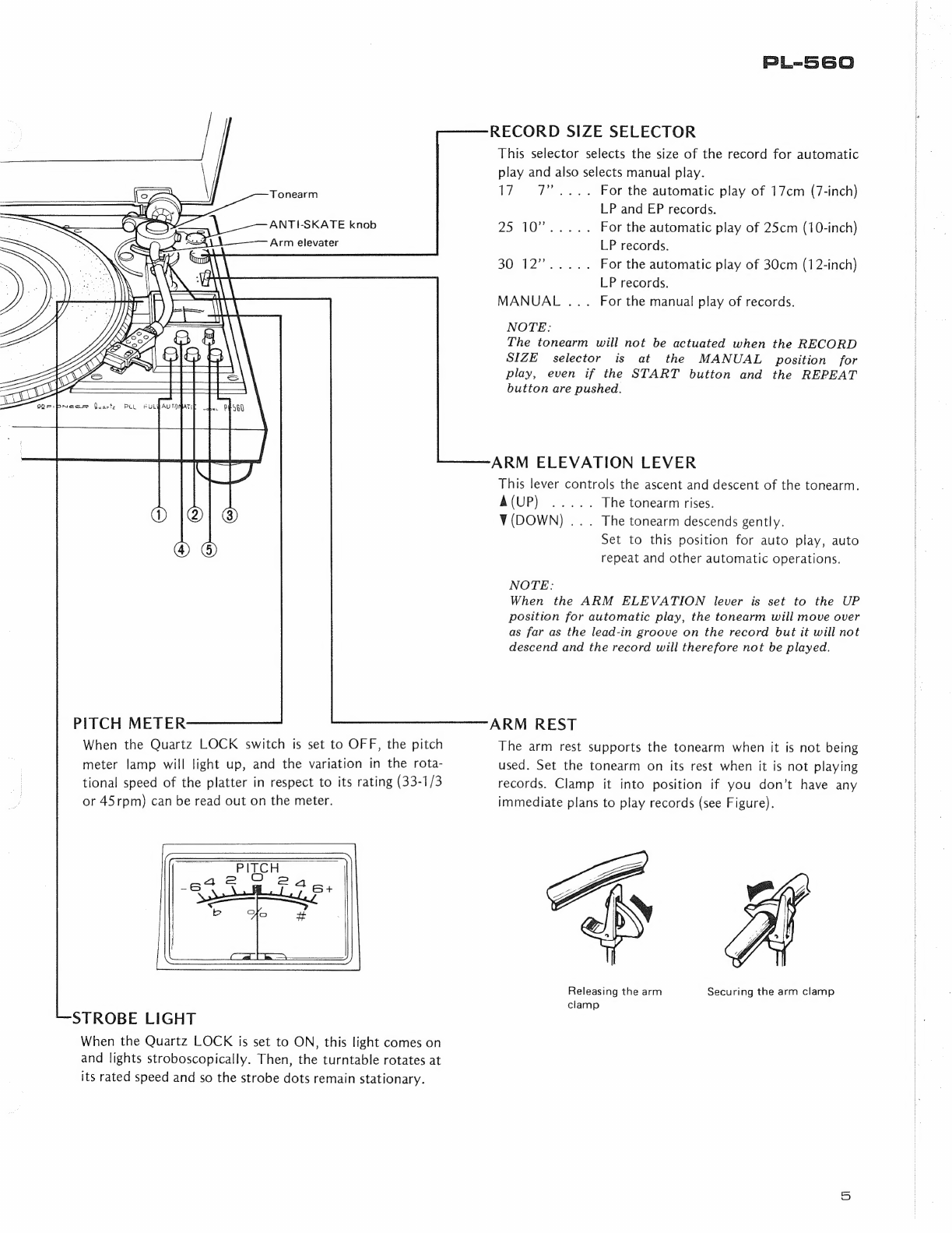
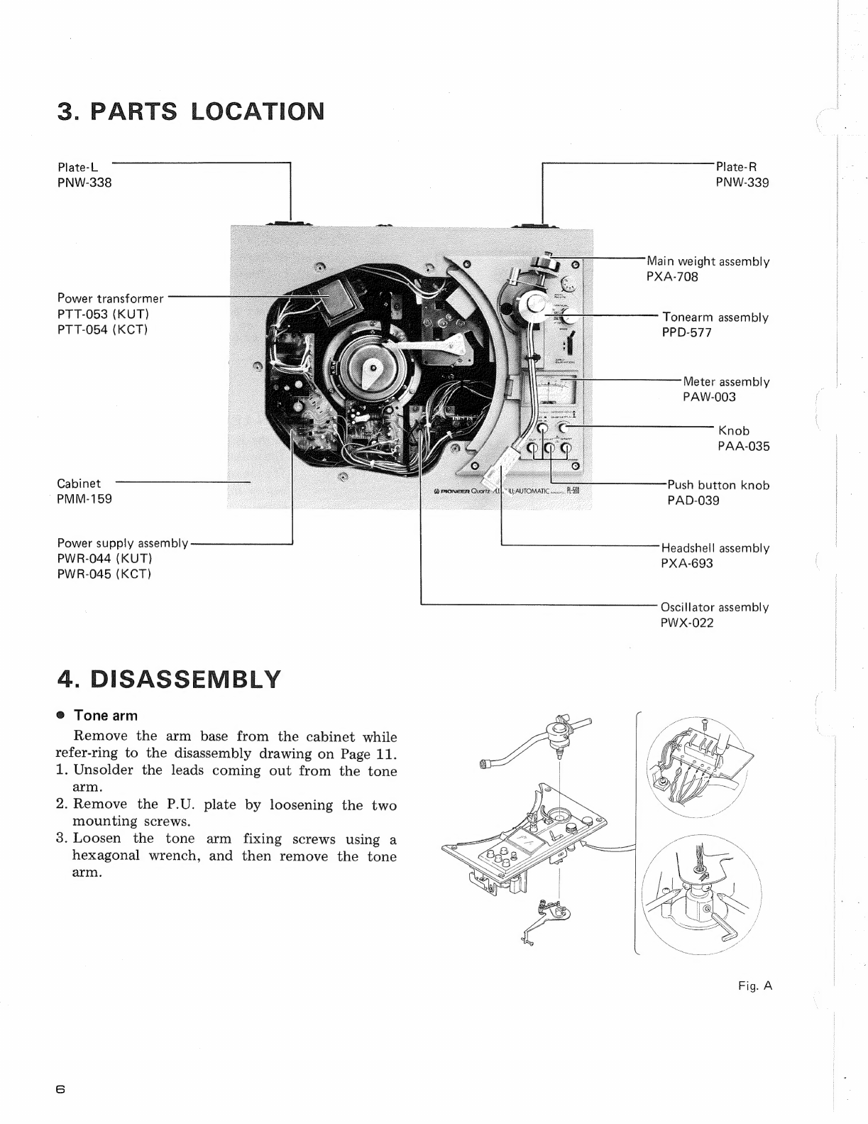
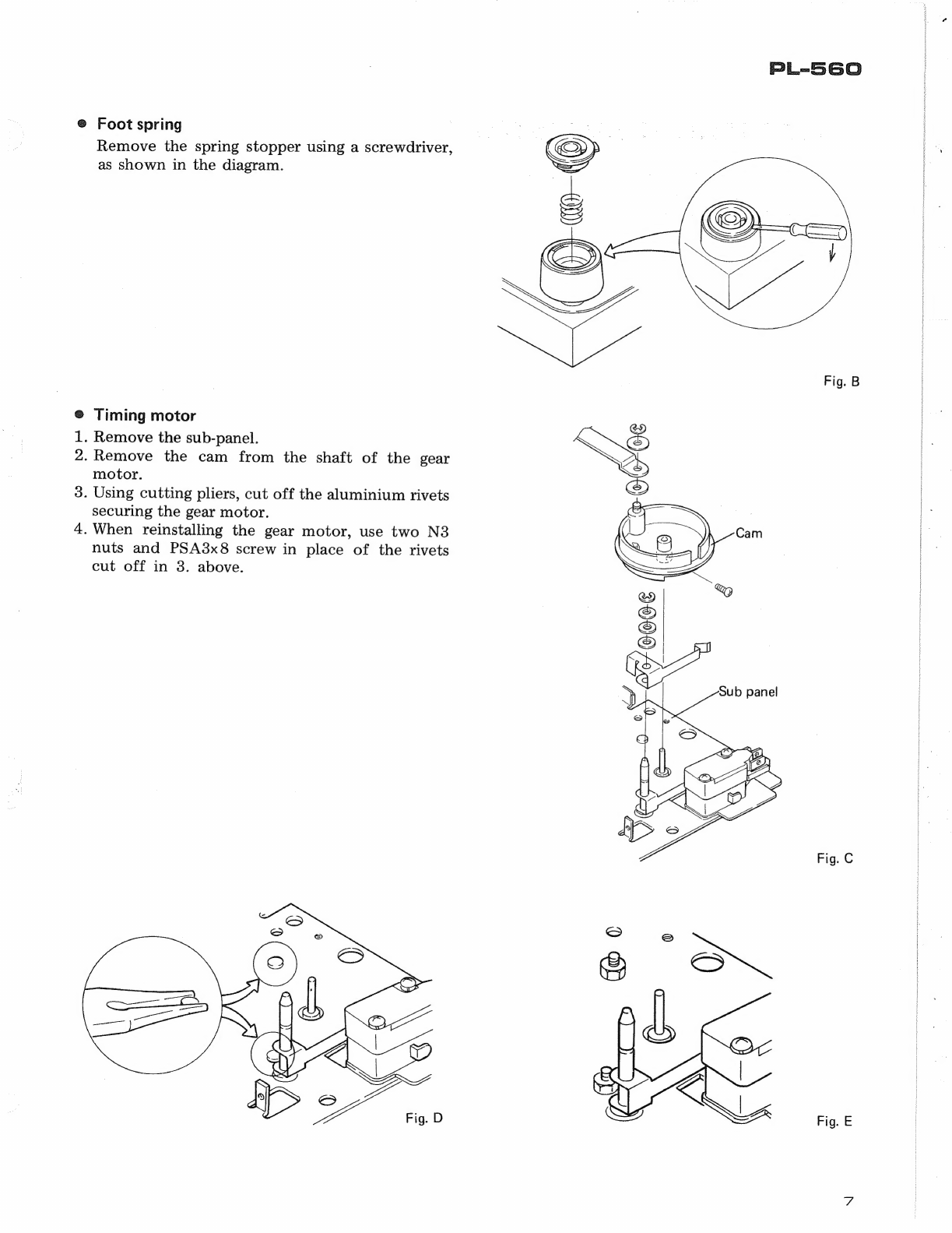
Pioneer PL-560 User manual

c/Manual
Service
motor
QuartzPLL
DIRECT
DRIVE
2
FULL
AUTOMATIC
TURNTABLE
PL=-560
Y
PIONEER

For
details
of
operation
of
the
mechanism
and
electronic
circuitry
of
the
PL-560,
refer
to
the
manuals
listed
below.
1.
Operation
of
mechanism
..............
PL-520
2.
Operating
principle
of
phono-motor
.....
PL-630
MODEL
PL-560
COMES
IN
FIVE
VERSIONS
DISTINGUISHED
AS
FOLLOWS:
Voltage
Remarks
120V
only
Canada
model
(without
cartridge)
;
120V
only
U.S.A.
model
(without
cartridge)
220V
and
240V
(switchable)
Europe
or
Oceania
model
(without
cartridge)
110V,
120V,
220V
and
240V
(switchable)
General
export
model
(without
cartridge)
110V,
120V,
220V
and
240V
(switchable)
U.S.
Military
model
(within
cartridge)
@
This
service
manual
is
applicable
to
the
PL-560/KUT,
KCT.
For
servicing
of
the
other
types
La
please
refer
to
the
additional
service
manuals.
CONTENTS
To
SPECIFICATIONS:
4.4545
uae
aie
eee
teu
oe
3
2.
FRONT
PANEL
FACILITIES
.............
4
BS:
PARTS.
LOCATION
§
x6
ih
beta
cous,
devadce
aac
6
4:
DISASSEMBLY
2:
dvd
parhtraceck
untae
eadee
6
|
5.
MECHANISM
ADJUSTMENT
.............
8
|
6.
ELECTRIC
ADJUSTMENTS
..............
10
7.
EXPLODED
VIEWS
TiV>
“AGADINO:
ahaiglac
Seay
ede
te
oe
ees
11
dia.
Bottom
Plate...
ace-tas.e
oe
8
ee
eee
se
8s
12
7.3.
Arm
Base
......
Bi
to
Ue
silcths
oh
deathecal
iB
te
Maat
13
7A.
Soulb
Parte).
4..0000.
2
vas
bese
Fe
Sas
15
So
PACKING:
<o-64
084.0040
Vee
see
es
we
tae
ea
16
9.
SCHEMATIC
DIAGRAM,
P.C.
BOARD
PATTERNS
AND
PARTS
LIST
9.1
Schematic
Diagram
..............205-
18
9.2
P.C.
Board
Connection
Diagram
........
20
9.3.
Drive
Control
Assembly
(PWG-017)
......
23
9.4
Control
Assembly
(PWX-028)
..........
24
9.5
Oscillator
Assembly
(PWX-022)
........
25
9.6
Power
Supply
Assembly
............-.
26
10.
D.D.
MOTOR
EXPLODED
VIEW
...........
27

1.
SPECIFICATIONS
Motor
and
Turntable
DEWE-
SV
SION
ag
th.
Lt
See
alee
aes
ie
Direct-drive
MOO
0
&
a.
Rae
aGala
etter
me
Quartz
PLL
Hall
motor
Turntable
Platter.
.
.
320mm
diam.
aluminum
alloy
die-cast
Moment
of
Inertia...
..
280kg-cm?
(including
platter
mat)
SHECUS
a5.
ge
ee
ewes
Poe
Oe
33-1/3
and
45rpm
Speed
Control
Range.....................2.
-£6%
Wow
and
Flutter...........
Less
than
0.025%
(WRMS)
Signal-to-Noise
Ratio.
........
More
than
73dB
(DIN-B)
(with
Pioneer
cartridge
model
PC-400)
Rotational
Characteristics
Build-up
Time
......
Within
120°
rotation
at
33-1/3rpm
Speed
Deviation
.................
Less
than
0.002%
Speed
vs.
Load
Characteristics...
.
Stable
up
to
200
grams
drag
load
Speed
Drift
.......
Less
than
0.00008%/h
at
33-1/3
rpm
Less
than
0.00003%/
degree
temp.
change
at
33-1/3rpm
Tonearm
Type........00%
Static-balance
type,
S-shaped
pipe
arm
Pffective
Atm
Length
ics
wy
aed Gis
oo
eke
s
221mm
Over
han
sy
ooo
aioe
SAA
lola
bp
oat
ed
15.5mm
Usable
Cartridge
Weight.......
4g
(min.)
to
10g
(max.)
Subfunctions
Full
auto
mechanism
Anti-skating
force
control
Stylus
pressure
direct-readout
counter
weight
PL-560
Cueing
device
Strobe
light
Pitch
indicator
Free
stop
hinges
Semiconductors
Ne
ein
a.
ig
Se
oe.
4
aS
es
wa
Renita
eee
wae
4
UP
AMSISUONS
a
deed
a:
See
aokegote
gk
gigas
Sc
e892 dete
ge
oa
teas
-
DI
OUCS
3
oo.
Fb
te
aor
ay
Klein
eee
Seek
ee
5
Fiat
ClCINGO
bse
gins
3S
ot
avert:
Glencwin
Ei:
em
yee
Oe
3
Accessories
EON
AD
LOR
a8
geet?
et
Are
cant
Wer
we
eodca
kn
Sah
obey
we
sad
4
1
DCECW
UMINEY
4.
20e
cat
tay
casts
Seki
Se
Hechinger
eg
oe
Bek
1
Cartridge
mounting
screws
...........0000
0000s
6
Cartridge
mounting
NUTS.
as
a4.6)s
c0ewawe
Ye
Ge
LER
Y
A
Z
Cartridge
mounting
washers
..............-00006
2
Operating
1NStructions
4.04
ys
oh
es
BE
Bo
SS
]
Miscellaneous
Power
Requirements
...............
AC
120V,
60Hz
Power
CONSUMDIION:
503.4
9a
4
64
Sete
ewe
BA
12W
Dimensions
...........
440(W)
x
145(H)
x
365(D)mm
17-15/16(W)
x
5-11/16(H)
x
14-3/8(D)
in.
WING.
sutatat
c
Sipty
aap
guste
ade ret
As
10.5kg/23lb
2
oz
NOTE:
Specifications
and
design
subject
to
possible
modification
without
notice,
due
to
improvements.

2.
FRONT
PANEL
FACILITIES
@
CUT
BUTTON
Push
this
button
to
stop
the
record
play.
When
pushed,
the
tonearm
will
rise
and
return
to
the
arm
rest.
The
power
to
the
turntable
will
then
be
switched
off
and
a
few
seconds
later,
the
platter
will
stop
rotating.
NOTE:
If
the
REPEAT
button
is
pushed,
the
tonearm
will
return
to
the
arm
rest
and
then
move
across
again
to
the
record.
(@
REPEAT
BUTTON
Push
this
button
when
you
want
to
listen
to
the
same
record
again.
Press
the
button
once
more
to
release.
NOTE:
All
you
have
to
do
for
repeat
play
is
to
press
the
REPEAT
button.
There
is
no
need
to
push
the
START
button
again.
@)
START
BUTTON
The
power
to
the
turntable
is
turned
on
and
the
platter
starts
to
rotate
when
this
button
is
depressed.
@
SPEED
SELECT
SWITCH
45
....
When
this
switch
is
depressed,
the
platter
will
rotate
at
45rpm.
Depress
for
playing
45rpm
records,
singles
or
EP’s.
33
....
When
this
switch
is
set
to
the
released
position,
the
platter
will
rotate
at
33-1/3rpm.
Release
for
playing
33-1/3rpm
records
like
LP’s.
(6)
QUARTZ
LOCK
SWITCH/PITCH
CONTROL
KNOB
@
When
the
Quartz
LOCK
switch
is
pushed
downward,
the
Quartz
PLL
will
actuate
and
the
strobe
light
comes
on.
Normally
use
it
in
this
position.
The
turntable
will
rotate
at
the
precisely
rated
speed
according
to
the
SPEED
SELECT
switch.
@
When
the
Quartz
LOCK
switch
is
pulled
upward,
the
Quartz
PLL
will
be
released
and
the
strobe
light
goes
off
and
pitch
meter
lamp
will
light
up.
If
the
PITCH
CONTROL
knob
is
turned
at
this
position,
the
rotating
speed
of
the
turntable
will
be
adjusted
up
to
6%
faster
or
slower
than
its
rated
speed.
If
the
knob
is
turned
in
the
(+)
direction,
the
turntable
rotates
faster,
and
if
the
knob
is
turned
in
the
(—)
direction,
the
turntable
rotates
slower
than
its
rated
speed.
The
variation
of
the
rotating
speed
can
be
read
out
on
the
PITCH
METER.
(Refer
to
“PITCH
CONTROL”)
Dust
ee
\
\ies
Rubber
platter
mat
Platter
PITCH
CONTROL
In
normal
circumstances,
the
platter
rotates
at
the
rated
speed
when
the
Quartz
LOCK
switch
is
kept
at
ON.
If
you
want
to
vary
the
speed,
set
this
switch
to
OFF
and
turn
the
PITCH
CONTROL
knob.
If
the
platter
rotates
faster
than
its
rated
speed,
the
musical
intervals
of
the
reproduced
sound
will
be
come
higher,
and
if it
rotates
slower,
they
will
become
lower.
Nowadays,
there
are
slight
variations
in
the
orchestra
and
other
tuning
sounds
recorded
on
discs.
Further-
more,
pianos
and
other
musical
instruments
for
the
home
are
tuned
to
high
international
standards
and
so
there
are
slight
discrepancies
in
the
musical
intervals
when
practicing
on
the
piano
along
with
a
record.
This
turntable
features
a
pitch
control
which
allows
you
to
compensate
for
the
slight
variations
in
the
musical
intervals
by
making
the
platter
rotate
up
to
6%
faster
or
slower
than
its
rated
speed.
The
com-
pensation
can
be
checked
by
ear.
An
adjustment
of
+6%
is
equivalent
to
about
a
semitone.
|

PL-560
|
RECORD
SIZE
SELECTOR
This
selector
selects
the
size
of
the
record
for
automatic
play
and
also
selects
manual
play.
\
Fonesin
17.
7”
....
For
the
automatic
play
of
17cm
(7-inch)
LP
and
EP
records.
=
ANTI-SKATE
knob
25
NOs
aoe
For
the
automatic
play
of
25cm
(10-inch)
Arm
elevater
LP
records.
geil
BOT
2
ee
eis
For
the
automatic
play
of
30cm
(12-inch)
WY
LP
records.
MANUAL
...
For
the
manual
play
of
records.
NOTE:
The
tonearm
will
not
be
actuated
when
the
RECORD
SIZE
selector
is
at
the
MANUAL
position
for
play,
even
if
the
START
button
and
the
REPEAT
button
are
pushed.
ARM
ELEVATION
LEVER
This
lever
controls
the
ascent
and
descent
of
the
tonearm.
BIUP)
ices
The
tonearm
rises.
Y(DOWN)
...
The
tonearm
descends
gently.
Set
to
this
position
for
auto
play,
auto
repeat
and
other
automatic
operations.
NOTE:
When
the
ARM
ELEVATION
lever
is
set
to
the
UP
position
for
automatic
play,
the
tonearm
will
move
over
as
far
as
the
lead-in
groove
on
the
record
but
it
will
not
descend
and
the
record
will
therefore
not
be
played.
PITCH
METER
ARM
REST
When
the
Quartz
LOCK
switch
is
set
to
OFF,
the
pitch
The
arm
rest
supports
the
tonearm
when
it
is
not
being
meter
lamp
will
light
up,
and
the
variation
in
the
rota-
used.
Set
the
tonearm
on
its
rest
when
it is
not
playing
tional
speed
of
the
platter
in
respect
to
its
rating
(33-1/3
records.
Clamp
it
into
position
if
you
don’t
have
any
or
45rpm)
can
be
read
out
on
the
meter.
immediate
plans
to
play
records
(see
Figure).
hy
Releasing
the
arm
Securing
the
arm
clamp
clamp
STROBE
LIGHT
When
the
Quartz
LOCK
is
set
to
ON,
this
light
comes
on
and
lights
stroboscopically.
Then,
the
turntable
rotates
at
its
rated
speed
and
so
the
strobe
dots
remain
stationary.

3.
PARTS
LOCATION
Plate-L
Plate-R
PNW-338
PNW-339
Main
weight
assembly
PXA-708
Power
transformer
PTT-053
(KUT)
Tonearm
assembly
PTT-054
(KCT)
PPD-577
Meter
assembly
PAW-003
Knob
PAA-035
Cabinet
Push
button
knob
~PMM-159
PAD-039
Power
supply
assembly
PWR-044
(KUT)
PWR-045
(KCT)
Headshell
assembly
PXA-693
Oscillator
assembly
PWX-022
4.
DISASSEMBLY
®
Tone
arm
Remove
the
arm
base
from
the
cabinet
while
refer-ring
to
the
disassembly
drawing
on
Page
11.
1.
Unsolder
the
leads
coming
out
from
the
tone
arm.
2.
Remove
the
P.U.
plate
by
loosening
the
two
mounting
screws.
3.
Loosen
the
tone
arm
fixing
screws
using
a
hexagonal
wrench,
and
then
remove
the
tone
arm.

PL-560
@
Foot
spring
Remove
the
spring
stopper
using
a
screwdriver,
as
shown
in
the
diagram.
Fig.
B
®
Timing
motor
.
Remove
the
sub-panel.
.
Remove
the
cam
from
the
shaft
of
the
gear
motor.
3.
Using
cutting
pliers,
cut
off
the
aluminium
rivets
securing
the
gear
motor.
4.
When
reinstalling
the
gear
motor,
use
two
N3
nuts
and
PSA8x8
screw
in
place
of
the
rivets
cut
off
in
3.
above.
Ne
Fig.
C
Fig.
E

5.
MECHANISM
ADJUSTMENT
Prior
to
making
any
adjustments,
check
that
the
PU
plate
shaft
is
located
in
the
center
of
the
cut
out
section
of
the
sub
panel
(as
shown
in
Fig.
1
below).
Cut
out
section
of
=
sub
panel
PU
plate
shaft
Fig.
1
Tonearm
Descent
Positions
The
tonearm
descent
positions
may
be
adjusted
by
turning
the
adjustment
screws
located
in
the
panel
holes
at
the
base
of
the
tonearm
pivot
(see
Fig.
2
).
When
turned
clockwise
..
the
descent
position
is
center.
When
turned
counter
clockwise
...............
the
descent
position
is
moved
outwards.
This
is
quite
a
simple
operation
when
a
test
record
is
used.
For
80cm
records
......
tonearm
descent
should
occur
in
the
304
to
319
count
range.
For
25cm
records
......
tonearm
descent
should
occur
in
the
252
to
267
count
range.
For
17cm
records
......
tonearm
descent
should
occur
in
the
173
to
184
count
range.
ey,
Tonearm
descent
position
~
adjustment
screws
The
tonearm
must
be
returned
to
the
arm
rest
to
provide
access
to
these
screws.
Fig.
2-a
Turn
adjustment
screw
in
the
counter
clockwise
direction
Turn
adjustment
screw
in
the
clockwise
direction
OD
D
Ss
oo
ed
AAA
Descent
position
too
far
inside
Descent
position
too
far
outside
Fig.
2-b
When
Tonearm
Fails
to
Return
1.
Adjust
the
stopper
angle
so
that
it
makes
contact
with
the
return
lever
pin
(Fig.
3).
Return
lever
Stopper
angle
Fig.
3
Arm
Elevation
Adjustment
1.
Leave
the
tonearm
in
the
up
position,
and
adjust
the
height
of
the
arm
elevation
sheet
so
that
the
gap
between
stylus
tip
and
record
surface
is
about
10mm.
(Fig.
4).
Arm
elevation
sheet
Fig.
4

Auto
Return
Lift
Off
Position
First
check
that
the
turntable
pin
(attached
to
the
turntable)
has
not
been
bent
over.
Strighten
out
if
necessary.
1.
Tonearm
lifts
off
too
soon.
Unscrew
the
screw
in
the
tip
of
the
PU
plate
by
a
suitable
amount
(Fig.
5).
2.
Tonearm
too
slow
in
lifting
off
Screw
the
PU
plate
tip
screw
in
further
(Fig.
5).
Screw
in
tip
of
PU
plate
Sending
plate
Screw
driver
Fig.
5
Faulty
Tonearm
Movement
If
the
tonearm
is
interfered
with,
or
halted
altogether
during
the
lead
in
operation,
tighten
up
the
screw
shown
in
Fig.
6.
NOTE:
This
adjustment
screw
should
be
made
neither
too
tight
nor
too
loose.
Q
eee
Bracket
=
<—
Nut
Plate
spring
Operations
plate
Fig.
6
Shorting
Switch
Adjust
the
switch
mounting
screw
so
that
the
gap
between
contacts
during
play
is
0.5mm
(Fig.
7).
Screw
dirver
Spring
mounting
screw
(for
adjustment)
—-
Fig.
7
PL-560

6.
ELECTRIC
ADJUSTMENTS
6.1
SPEED
ADJUSTMENT
WHEN
QUARTZ
LOCK
IS
OFF
1.
Put
the
quartz
lock
off.
2.
Turn
the
ADJUST
knob
on
the
control
panel
to
the
mechanical
center
position.
3.
Insert
a
screwdriver
through
the
small
hole
in
the
baseplate
of
the
player,
and
turn
the
semi-
fixed
speed
adjustment
potentiometer
VR:
until
the
strobe
pattern
on
the
turntable
becomes
stationary.
6.2
ADJUSTMENT
OF
D.D.
MOTOR
OPERATING
POINT
@
Adjustment
Conditions
Connect
the
SP
and
TP23
terminals
of
PWG-017
to
each
input
of
a
double
image
oscilloscope
(synchroscope).
Put
the
turntable
in
the
Quartz
Lock
ON
condition,
and
then
start
it
up.
®
Method
of
Adjustment
1.
Observe
the
output
waveforms
from
SP
and
TP23
(Fig.
8).
(Two
output
pulses
from
terminal
TP23
will
correspond
with
one
pulse
from
terminal
SP.
2.
Adjust
the
semi-fixed
resistor
in
the
control
circuit
assembly
(PWG-017)
so
that
the
rising
part
of
the
pulse
which
comes
out
of
terminal
TP23
fits
into
the
middle
of
the
pulse
which
is
generated
at
terminal
SP.
For
33-1/3
rpm,
adjust
VR21.
For
45
rpm
adjust
VR22.
Waveform
at
TP23
terminal
Waveform
at
SP
terminal
Fig.
8
10
6.3
METER
ADJUSTMENT
ds
Adjustment
Conditions
Connect
a
frequency
counter
between
the
TP1
and
Gnd
terminals
of
the
oscillator
assembly
(PWX-022).
.
Turn
the
speed
adjust
knob
to
its
mechanical
center.
3.
Put
the
Quartz
Lock
off.
.
Adjust
VR3
Adjustment
.
Put
the
speed
selector
button
in
the
‘45”
position.
.
Turn
VR
in
the
oscillator
assembly
(PWX-022)
until
the
reading
on
the
frequency
counter
becomes
750.0Hz.
.
Turn
VRz2
in
the
control
assembly
(PWX-028)
until
the
meter
reading
becomes
zero.
.
Put
the
speed
selector
button
in
the
“33”
position,
and
turn
VR:
until
the
meter
reading
becomes
zero.
.
Turn
the
speed
adjust
knob
until
the
reading
on
the
frequency
counter
becomes
795Hz
(750Hz
+6%).
so
that
the
meter
indication
becomes
+6%.

PL-560
NOTE:
7
8
EX
P
LO
DE
D
Vi
EWS
|_|
marked
parts
cannot
be
supplied.
7.1
CABINET
A
Hinge
assembly
A
Rubber
mat
assembly
PEA-034
(KUT)
Dust
cover
PEA-032
(KCT)
PNV-014
PBA-073
B
B
RW
3.1
x
13
Turntable
platter
PNR-072
-
PBA-076
4
—
PSB
4x
8
|
la
_B
Cabinet
|
-338
AK
PMM-159
ewe
‘
Sy
Ege
Plate-R
PNW-339
C
Foot
rubber
Cc
PEB-086
Spring
PBH-181
Stopper
PNW-415
Screw
PBA-066
Spring
PBH-179
a
Screw
PBA-077
See
page
12
11

NOTE:
7.2
BOTTOM
PLATE
[|
marked
parts
cannot
be
supplied.
FW
4
_-—~
Power
transformer
PTT-053
(KUT)
&
7
PTT-054
(KCT)
S
Rubber
cushion
D.D.
Motor
ae
PEB-037
PXM-065
(Include
oscillator
assembly
PWX-022)
PSA4x8
@
B
AC
power
cord
Power
supply
assembly
PDG-010
Sig
PWR-044
(KUT)
>
SX
PWR-045
(KCT)
P.C.
board
holder
Cc
8
|
aie
Cord
holder
C
Output
cord
PD
X-008
(KUT)
PDX-007
(KCT)
Oscillator
assembly
PW
X-022
\
5
x
D
D
12

7.3.
ARM
BASE
Meter
assembly
PAW-003
Meter
lamp
PEL-036
Push
button
unit
PXT-277
Nylon
washer
4.26
x
10¢
x
0.5t
EW
aC
Polystyrene
washer
4.2¢
x
8¢
x
0.25t
Spring
PBH-189
Button
guide
PNW-461
SS
SS
a
Ja
|
A
Steel
ball
5/32”
Washer
3.26
x
10¢
x
0.8t
Spring
PBH-188
Neon
lamp
PEL-03
»
A
Cam
spring-B
ee
PBH-018
ey
EV
cam
PNW-251
Neon
lamp
holder
EW
3
PNW-455
U
eo
Rubber
cap
N6
Microswitch
PSF-007
PSA
3
x
16
PSA
3 x
16
Microswitch
PSF-006
Insulator
PEC-044
PAC-017
Arm
rest
stand
PLA-382
SF3x4
Arm
rest
unit
PXT-292
PNT-516
~J
Sheet
cushion
Size
selector
knob
SF3x5
Adjust
cam
PNW-458
CS)
——
washer
PBE-012
Rubber
bush
Washer
PBF-005
Shaft
PLA-371
SS
_
PNR-086
Lever
PNB-432
PXT-201
Screw
KBA-002
(Gorm
(
V7
N3
Plastic
screw
PM3x
15
Washer
4
PBF-005
Arm
base
PPD-577
Elevation
sheet
PNW-577
ee
ee
Adjust
shaft
unit
Tonearm
assembly
PL-560
NOTE:
[|
marked
parts
cannot
be
supplied.
Adjust
cam
unit
PXT-109
Spring
PU
plate
unit
Washer
PNB-224
PBH-190
444

NOTE:
[|
marked
parts
cannot
be
supplied.
7.4
SUB
PANEL
EW
3
|
ae
5
Nylon
washer
EW
3—_
Lever
4.
A
=
KNA-100
Qa
26
x
109
x
0.5t
oe
washer
Al
5
W4x0.1t
=
Nvlon
washer
:
|
3.26
x
5.56
x
0.3t
4.2
x
10%
x
0.5%
aever
iL
ee
Sprin
®
-.
g
Be
Fwa—<e
wee
Teflon
washer
4.26
x
8¢
x
0.3t
Rotor
aun!
PXA-355
(KCT)
|
PXA-406
(KUT)
|
Colle
:
KLA-068
B
~
Lever
KNA-104
EW
3
Spring
B
Switch
FW
4
KNA-102
:
KSN-001
Teflon
washer
ra
3
4.26
x
86
x
0.3t
FW
4
eo
@
Lever
Spring
A
ya
:
KNA-101
PM
3x8
ge
ENB
he
bee
-Spring
Angle
Plate
Rubber
KBH-040
PNB-341
PNM-011
cushion
PM
2.6
x
25
ul
SS
PEB-059
|
ic
L
Cc
:
S>
Rubber
bush
SW
2.6
P.C.
Board
(output)
PYY-021
Microswitch
y
PSF-007
et
Microswitch
spacer
PSF-006
Spacer
cae
Plate
Insulator
KWM-015
PEC-044
D
Timing
motor
PXM-064
Stopper
unit
PXA-206
1
15
8.
PACKING
Cartridge
mounting
washer
B22-642
Cartridge
mounting
nut
B71-653
Cartridge
mounting
screw
B11-657
Upper
pad
;
PHC-049
Cartridge
mounting
screw
KBA-044
Main
weight
assembly
ting
instructions
Operating
|
By
AOS
PRB-111
Cartridge
mounting
screw
Headshell
assembly
KBA-045
PXA-693
Screwdriver
KEX-002
Rubber
mat
assembly
Protector
PEA-034
(KUT)
PHA-061
Packing
PEA-032
(KCT)
PHA-068
j
yl
Spacer
fl!
PHC-060
oD
|
2
Vinyl
bag
—
H56-603
Vinyl
sheet
PHL-024
Cok-
6-5
Packing
case
PHG-279
(KUT)
PHG-281
(KCT)
Flap
stopper
KNK-403
16

Code
numbers
of
resistors
used
in
Pioneer
equipment
are
expressed
in
the
following
way:—
Code
number
—~————-———>
RD
%
PS
473
J
NL
Type
of
resistor
<
J
|
Power
rating
Shape
(tubuler)
Resistance
(code
value)
Tolerance
Low-noise
marking
<———
Furthermore,
in
the
list
of
parts
found
in
the
Service
Manual,
the
resistance
(code
value)
part
of
the
above
code
number
is
expressed
as
(OO
or
i
ms
Resistors
included
in
the
Service
Manual
list
of
parts
|
Ex.
RD%PSOO0O
JNL
When
ordering
resistor
components,
first
ascer-
tain
the
actual
resistance
value
from
the
circuit
diagram,
and
then
convert
it
into
code
no.
form
as
shown
in
the
following
examples.
For
further
details
on
code
numbers,
refer
to
“Tuning
Fork”
VOL.
1.
Ex.
1
For
DOOO
Codes
*
General
resistors
CJ
C
O
fe]
Significant
figures
Multiplier
(10%)
*
Resistors
with
fractional
values
C
C]
Ed
CO
Ei
OR
115
Significant
figures
Decimal
point
i)
O
R
C)
ee
Significant
figures
Sur
td
Decimal
point
Ex.
1
Nominal
resistance
|
Significant
figure
Multiplier
|
Resistance
|
(2)
{three
figures)
(10X)
value
a
5.1
BVO
=
shatadtn
cee
5R10
5.62
562
li
ea
es
5R62
10
100
9
.V...e.
10RO
22.5
P25
aed
22R5
110
110
x70°
1100
1k
1
(1000)
100
x10
1001
1.56k
1
(1560)
156
x10
1561
10k
2
(10000)
100
x10
1002
33.6k
2
(33600)
336
x10
3362
112k
3
(112000)
112
x10
1123
1M
4
(1000000)
100
x10
1004
1.56M
4
(1560000)
156
x10
1564
Ex.
2
For
OOO
Codes
*
General
resistors
0
CO
O
ae
Significant
figures
Multiplier
(10%)
*
Resistors
with
fractional
values
C
O
O
ORO
Significant
figures
Decimal
point
Ex.
2
Nominal
resistance
(2)
Resistance
value
code
Significant
figure
Multiplier
(two
figures)
(10X)
os
|)
<“@e
~
iiss
1.5
fo.
tata
1R5
1
01
«10°
010
22 22
x10°
220
330
33
x10!
331
1k
2
ps6
10
x10
102
5.6k
3
(5600)
ne
aa
28?
68k
3
(68000)
oe
ee
oe
820k
‘5
ene
82
x10
824
1M
5
1
(1000000)
He
a
vp
a
22
x10°
(2200000)


Peace
Oe
Sa
ek
args
OE
Sc
ee
oe
ee
el
_
6
_|
7
9.2
P.C.
BOARD
CONNECTION
DIAGRAM
ARMATURE
CO!
Power
Supply
Assembly
PWR-044
NEON
PEL-031
METER
AC
120V
ASSEMBLY
6OH2z
PAW-003
Saas
|
I
1
i
t
|
{
i
SUB-PANEL
ASSEMBLY
ae
Pee
|
1
\
;
|
|
\
i
{
i
!
oe
fue
t
rg
tf
|
WHT
Sie
eae
I
O
3
'
<>
|
j
ATC
OR
O
OQ
S1
i
Q
:
S
START
y
O
SIG
RED
REPEAT
96 M7
1)
_984_!
S
|e
BS
BRN
SINC
RED
©)
STOP
““~o
a
©
S2
Oscillator
Assembly
PWX-022
Cc
roe
1
5
6
7
20

_
3.
4
|
5
pe
Oe
ed
8
9
ARMATURE
CORE
ASSEMBLY
PTL-003
[oa
oo
eee
ge
ee
ea
NEON
PEL-031
A
|
Drive
Control
Assembly
PWG-017
METER
ASSEMBLY
|
;
Tare
PAW-003
ms,
: 2
1.90
s
SPEED
eae
:
Es
DETECTOR
I
i
So
ASSEMBLY
1
a
g
PWX-023
PA2005
5
3)
ee
Bt
{
: “
‘
|
.
)
i
|
|
\
,
|
1
I
|
I
{
{
{
{
eS
t
:
!
\
{
ek
{
{
O
|
{
t
|
Giada
eed
|
\
|
|
|
WX-022
|
,
Cc

PL-560
1
i
eee,
Peart
Sens
ee:
eT
CEO
ea
nee
6
|
9.1
SCHEMATIC
DIAGRAM
'
a
Sa
os
ee
Se
:
DRIVE
CONTROL
Ass’y
OSCILLATOR
Assy
PWX-022
PWG-
O17
vee
2
G_
Tee3["
stop
CONTROL
Ass’y
PWX-028
A
Ql
PDIOO3
\vce2
|
ar
4G
a@i,2
escaaee
;
a.
Bele
:
:
:
A
1O7V
|
vec2}
10.7V
“LAs
iL
10.7V
z
Panes
emu
i
1
t
Q2i
PAZODG
O
Vee
2
10.7V
aii
d
a
“:
a22
PAZ2005
+
cA
RI
gik=
CS
mm
MCE
'
|
C34
10/38
22k
R2
Ae
(G)
[°%%5
047/35
Q3
3/4
Ho
oO
'
100k
47k
,
i
'
1/50
+]
038
LB
|
gle
a
Si
RUB
(10k
:
10/35
2m
RI2
'
C10
0.01
Is
oh
R29
240k
S
eane
1$2473
—
3
SOL
’
t
{
R3I
uc
‘
ac
‘
ae
L
Ria
36
|
M2
feat
“
bi
i
el
wow)
ARMATURE
42/6
RG
IM
C3
|
ol
cana
Q2
15k
(G)
eek
|
|
4
t
a
HA~HC
Cc
E
;
ee
|
-
1
t
q+
RQ
(i
+
?
VR3
t
DEES
Sor
TP
PHE
303FA
ORE
Ass’y
i
00033
‘4
c
680
C8
fp
|
ata
t
:
.
PTL-003
03
1/4
ook
OS
As
(8)
470/63
:
:
(NP)
R2
Ik
R27
|
c30
R4
47k
a
Ci
x
|
|
i
82k
7
O01
a
oes
ae
4
=
z,
|
re
WW
Be
ca
‘
33p
|
:
220
|
|
;
f
Res
cat
rr
3830
|
|
sen
res
RIS
36k
(G)
68k
1/50
k
RT
RB
22k
(B)
C2
56p
:
(NP)
+
1
4
4
E4
AA
9
Vv
R224
C23
R28
56k
C35
0.33/35
’
150k
39k
rT
.
R3
680k
'
220k
@680p
C33
0.056
ae
R2I
1
10k
ey
62k
os
Tees
Trea
|"
R32
t
0.01
(6)
t
0.0056
ae
22k 22k
56k
SPEED
DETECTOR
'
317
'
.
C22
|
VR21
vR22
Ass’y
30k
a
0.04
isk
#758
636
PWX-023
(B)
(B)
pig
eet
0.0047
10/16
‘
Zz
71
'
i
‘
Lin
t
Cal
FGI
stl
|
:
4.
'
0
|
vn
rT
et
|
st
---
===}.
F=5
i
(8)
C2
-
FG2
VR2-b]
JVR2-a;
vR2
-
763,
j
4
PITCH
CONTROL
:
4
4
a
fe.
1
e
°
ab
ste
s
1
"i
°o
t
—-
>
‘
5
‘
x
ot
*|
'
oO
w
x
L
oft
nn
=
NS
Eo
4
a
a)
~
N
=
een
ee
oS
oO
°
=
4
3
N
=
Pe
1
ar
mas)
aot
DH
fo)
2°
“iy
ae
Q
1
ol8y
ats
=
“3
a
:
=a
6
°
'
a
m2
ol
Ba
1
zo
/
|
ou
am
i
3
nN
‘e
Of.
80
w
oat
a
O
<
s
oO
ar
i)
N
<
X/CR
Li
--O—OQn
=
<>
>
oD
Om
Gnd
JGnd
[COI
|cO2
jad!
[402
[Gnd
|x/cR
ae
<fT
(|
4
aes
SUB-PANEL
Ass‘y
,
PWR-045
(KCT)
.
POWER
SUPPLY
Assy
PWR-044
(KUT)
CS
ee
ee
eS
SS
ae
|
vs!
NE+
|
D3
R2
8.2k
|
R3
100k
H
©
bein
Cc
|
3
-
TR3I
>i
150V
pris
L
ee
2sci279$
NE-
PEL-O3I
METER
Ass'y
:
WHT
>
OR
=
2
1sise8+|
&,
feNes
Ra
as
R6
47k
ST
MBS)
O
‘
ui
:
NWA
{
1
|
2
10/250
240k
R5
‘
:
1
+
[7
1
START
we
O
JR32}
a
sn
REPEAT
|
OR
I
C24
|
p2
an
—_
TR2I
i
eee
1
O%5|+
7’
WZ-260
J
c3
os
a
\
°
1g—p—t
28.2V
133/35
(Ss)
i
i
1
RED
:
;
|
RI
al
cy
;
METER
LAMPY
$2
|
tk
(A)
2
c4
Pa
t
i
8V
55mA
Stud.
ke
I
cM
2
ce
0.01
220k
X/CR
i
(0)
SWITCHES
:
{
{
+1a7
50
R
S1
START
/
REPEAT
ON
—
OFF
3
:
ghee
i
>
:
ZS
|
+8
i
H
$2
CUT
(
STOP)
ON
~—
OFF
BRN
REO
:
ieate
aes
;
38v
27v
I
'
S3
MICRO
(START/REPEAT)
ON
-—
OFF
sa.
DI
aay
a!
28C945P
RB
33k
WZ-08)
|
i
are
So
u
$4
MICRO
(STOP)
ON
—
OFF
at
(PCX-O10)
a2
280234
oon
TH
:
S5
SPEED
45rpm
—
33
¥3rpm
Za)
R?
Qs
‘
S6
QUARTZ
LOCK
ON
—
OFF
H
Se
240
(A)
8V
{us
bc
a
ACI
ee
ae
ascent
(3W)
i6V
Y
RESISTORS
:
The
underlined
indicates
the
switch
position.
ahs
ole
AC2
rr
tt
a4
2S0571
|
IN
OHM
I/4W
#5%
TOLERANCE
UNLESS
OTHERWISE
|
as
2SC945P
‘
NOTED
k:kQ
M:MN
(G):
£2%
TOLERANCE
Le
-
- a
Pa
er
28
ee
pees
|
CAPACITORS:
SH
Wo
pie:
Jawan
cM
IN
pF
UNLESS
OTHERWISE
NOTED
p:
pF
D
V:
DC
VOLTAGE
AT
NO
INPUT
SIGNAL
This
is
the
basic
schematic
diagram,
but
the
actual
circuit
may
vary
due
to
improvements
in
design.
1
2
Le
a
8
tre
se
i
ee
19

PL-560
9.3
DRIVE
CONTROL
ASSEMBLY
(PWG-017)
TP23
H
Qazi
PA2Z004
a22
PA2005
R29
240k
Loe
mie
ee
co fo
sam
a
mee
oe
C28
°
ARMATURE
0.47/35
CORE
Ass’y
|
PTL-0O03
0.
eee
|
;
O
|
R26
C3!
68k
1/50
R28
56k
a
R23
Zoe
22k
22k
VR22
a
15k
B)
(8)
0
tae
=a.
t
Os
ce?
1
Gos
tL
2
see
|
col
co02
co
Part
List
of
Drive
Control
Assembly
(PWG-017)
CAPACITORS
RESISTORS
Part
No.
Symbol
&
Description
Part
No.
Symbol
&
Description
CEA
101M6.3NP
C21
PCP-019
VR21,
VR22
15kQ-B
CKDYF
403250
C22
CKDYB
681K
50)
C23
RD%PS
000
J
R21—R30,
R32—R35
CQMA
154J
50
C25
CQMA
104J
50
C26,
C30
RD%PS
000
J
R31
RSiP
O00
J
R36
CQMA
153J
50
C27
CSZA
R47K
35
C28
SEMICONDUCTORS,
OTHER
COQMA
104K
50
C29
CEA
810M
SONP
C31
Part
No.
Symboi
&
Description
CQMA
563K
50
C33
PA2004
Q21
CEA
010P
50
C34
PA2005
Q22
CSZA
R33K
35
C35
CSZA
100K
16
C36
PCX-039
HA,
HB,
HC
Hall
element
(PHE303FA)
CEA
101P
35
C37
CEA
100P
35
C38,
C39,
C40
PTL-003
Armature
core
assembly
CKDYF
103250
C41
23
Other manuals for PL-560
2
Table of contents
Other Pioneer Turntable manuals

Pioneer
Pioneer XDJ-1000 User manual

Pioneer
Pioneer PL-5 User manual

Pioneer
Pioneer PL-530 User manual

Pioneer
Pioneer PLX-1000 User manual

Pioneer
Pioneer PL-05 User manual

Pioneer
Pioneer LD-V4300D User manual

Pioneer
Pioneer PL-5 User manual

Pioneer
Pioneer CDJ-2000NXS2 User manual

Pioneer
Pioneer PL-41 User manual

Pioneer
Pioneer PL-X505 User manual

Pioneer
Pioneer PL-112D User manual

Pioneer
Pioneer PL-55X User manual

Pioneer
Pioneer PL-51 User manual

Pioneer
Pioneer PL-500 User manual

Pioneer
Pioneer PL-L1000 User manual

Pioneer
Pioneer PL-100 User manual

Pioneer
Pioneer PL-520 User manual

Pioneer
Pioneer PL-05 User manual

Pioneer
Pioneer PL-518 KUT User manual

Pioneer
Pioneer PL-990 User manual