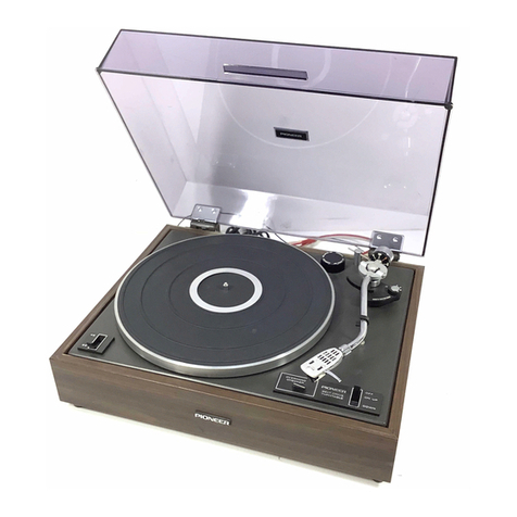
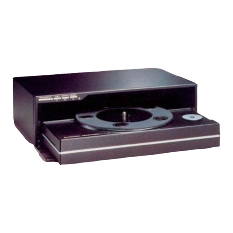
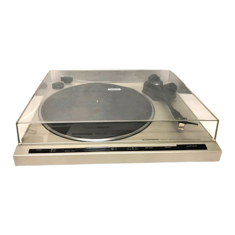
Pioneer PL-L1000 User manual

LINEAR
MOTOR ARM
STEREO TURNTABLE
OPERATING
INSTRUCTIONS
@PIONEER
"
HET
HBT
S/G
Thank
you for buying this Pioneer stereo turntabl
e.
Please read through these operating instructions and then
you
will know
how
to
operate
your
model propely. After
you
have finished reading the instructions,
put
them away
in a safe place for future reference.
These operating instructions are based
on
the
model HET,
and
th
ey c
an
be used for the HBT and 5/G models.
The
differences between the models are given below.
Power Requirements
HET, HBT models:
AC
220
/2
40V
"-(
switchable), 50, 60Hz
5/G model: AC110/120/220
/2
40V'\.(switchable), 50, 60Hz
NOTE:
R•ad
rhrough rho sscrion
on
rho
"LIN
E VOLTAGESELECTOR
SWITCH"
before
us
ing
your
rurnrablo
and
check thor rho
volt~>ge
wlec
tor
switch
is
sot
correctly
for
us11
in your
area.
Accesso
ri
es
HET, HBT models:
A cartridge is
not
provided with these models.However,
screws
for
mounting
the
cartridge. as well as washers
and nuts come wi
th
each model, and so before use,
provide yourself with the cartridge you intend
to
use.
read through the section "ATTACHING THE
CARTA lOGE" and then attach the cartridge
to
the ac·
cess
orv
headshell.
5/G
model:
This model comes with tho PC·6
00
cartridge (which is
a
tt
ached to
the
accessory headshell
).
Scr
ews
for m
ount
·
ing
a cartridge as we
ll
as washers and nuts are
not
pro·
vided.
IMPORTANT
----------------------------
--~
To
pr
ovent eloc
rr
ic
shock.
do
not romove cover. No user
servic~
DbltJ
pans
insldD,
r•
fer setvicing
ro
qunHfied
s1rvlce
personnel.
Alw1ys
di~t:onncct
all
tho
equipmt~nt
from
tht
m•
i
ns
supply
wMn
dlsconn«ring the
signal
leads.
Tht power cold should
be
conntJCttd
l•st. make sure thsr thllpowerswitch
is
off.
Unplug
tht
sec
from tho wall
wckot
whtn
It
is
not
to
b11
used for
on
oxt~ndod
ptrlod
of
time.
FOR
US
E IN UNITED KING
DOM
AND
AUSTRALIA
CAUTION 240V: Mains supply voltage
Is
factory
adjusted at 240V.
FO
R
USE
IN
UNIT
ED
KINGDOM
Tht
w
ir11s
;,
this mains lelld
11ro
coloured ln
«cordance
with
thD
following cord:
Blue:
N~utnl
Brown: Live
As
thl
colours
of
the wirts In thD mains lead
of
this apparatus
may not
corrBSPond
with tho colour
ed
marklng ldentllylng tho
UJrmlnols
in
yourplugproceed
os
loll
oW$
.
Tlr11
wire whlch
is
colouriJd blue must
})o
connoccod co tho
tOmJ/nol
wh
ich is morked wltll
th
olo
tr
er
No
r coloured
b
lt~
k.
The wire which is coloured brown must bl! connecced
10
th
u
rormlnal which
is
markedwith
lhl
/O
rt
llr
L
or
coloured
rtJd.

CONTENTS
Assembly Procedure ... .......... ........
lnstalletion
•....
..
. .
..•
•....
....
•
••
.
•.
Connect
io
ns
to
S1
·ereo
Amplifier
...
••••
•
••
...
AdjuJtlng the Tonearm . . •
•.....
, . • •
••.
. . •
2
6
6
7
Panel Fecilitl
ts
. . . . • • . . . • • . . . . . . . . . • • . . .
10
Ope11ti
on
. . • . • . . • . . • • • • . . . . • . . • . • • . . .
t2
ASSEMBLY
PROCEDURE
\
---.........
Rubbet plettt1'
IN<-
----
-
-....
Platttr
--
- - ,
Soeedswh<:h
- - -
""
Disc
slr•
rwiltch- - -
-.../
,._,
owillch--
-
---"
A"
n
•levttion
.,.;«.,._ _
.-./
Aemote OOIHetlon
k~ob
·-
-
--"
Mllnttntnc:e . .
....
•
......
..
. .
•.•
...•
, • 14
Line Voltage Selector
Sw
itch
..
......
•.
, . . . . 14
Features . . . . . . . . . . . . . . . . . . . . . • . . . . . . . 15
Troubleshooting . . . . • • . . • • • • . . . . . • . . • . . .
16
Speeificetions . • . • . • . . • . . . . . . . . . . . . • . . . 17
r-
--
·
G!Ikllbon

STEP
1: CHECK
THE
ACCESSORIES
The styrene
pad
contains
the
pans
shown
in
the
figure.
Check
that
they
are all inside.
The
EP adapter
is
used
for
records with a large
center
hole.
Sty
r
ene
pad
[
L
arge
s
iz
e
cou
nterweight
,.-.:..._ Level
c~
EP
adapter
Small
size
counterweight
Styrene
pad
~
Planer
clamp
screws
Overhang
gauge
'---
Screwdriver
Cartridge
mounting
parts
Head
shell
(H
ET,
HBT
models
only)
STEP
2:
REMOVING DUST COVER
1. Fully
open
the
dust
cover.
2. Hold the
dust
cover, and l
ift
it
off
by
pulling it straight
upward.
STEP
3:
REMOVAL
OF
TONEARM
CLAMP
SCREWS
AND
TONEARM
HOLDER
A
1. The
tonea
rm
is
anchored
to
prevent damage which
mi
ght
be sustained during transp
ortation.
Use
a Phillips
screwdriver
to
remove
the
four tonearm clamp screws on
the
re
ar
panel as shown in
the
figure.
·
r;:
~-
(,
fJw
'"
/
;;1
~.
·
;>
"'
c!
I
~
~)
1
1#
/
. .
Lronearm
clamp
sc
rew
:
::
-PIO
N
EER
2. Pull tonearm holder A in
the
direction
of
the
arrow
given in Fig. A
and
then
remove it. When removing
the
ho
lder, bend its c
enter
part with
your
fingers
as
in
F
ig.
B.
. T
arm
holderA
f one
-
~
-
~
Fig. A
I /
--/
; v
't
/'
~
~
•
'-
Fi
g.
B
ST
EP
4:
REMOVAL
OF TONEARM HOLDER
B
1. Rotate
the
tracking·force scale ring 5 - 6
tu
rns in
the
directi
on
of
the
arrowshown in
the
figure.
2. Use a Phillips screwd
ri
ver
to
remove
the
two
clamp
screws.
Be
careful n
ot
to
drop
screws into the hole in
the
tone·
arm base.

3.
Remove
the
tonearm
hold<!r 8
from
the
tonearm
base.
'---Toneerm
t..lst
STEP
5: REMOVING TRANSIT
SC
REWS
Re
move three
transit
scn~ws
w
ith
a Phillips
scn~wdriver
as
shown
below.
ii'I--
-"Trensft ICt'IW
®
I
..
STEP
6: MOUNTING THE PLATTER AND
RUBBER PLATTER
MAT
1.
Slip
the
platter
over
the
center
shaft
and secure
it
usi
ng
the
accessory
platter
clamp screws (3) and
an
ordinary
slot
screwdriver.
2. Place
me
rubber
platter
mat
on
top
of
th
e
platter
.
Plttttr
c•mp-
--
-._
SCfiW
Ctnttr
shift
·
4
STEP
7: MOUNTING THE HEADSHELL
lnottll
the
certridge as d
tseribld
on
page 5 "ATTACHING
THE
C
ARTR
IDGE" and
attiCh
tht
hudshell
to
tho to
no
·
arm H follows:
Insert t
he
headshell
into
the
end
of t
he
tonearm, and
rotate
the
locking collar
In
the direction Indicated by
the
arrow
in
the
figure until
it
stops.
Then
secure
it.
STEP
8: MOUNTING THE
CO
UNTERWEIGHT
Slip
the
small size
counterwe
i
ght
onto
the
trackin
~tf
orce
scale ring
at
the
end
of
the
tonearm.
Next, adjust
th
e
position
of
t
he
weight
so
that
the
clearance between
the
weight and
the
tracking-force
SC4Io
ring comes
to
0·\mm
(depending
on
t
he
weight
of
the
cartrid
ge, It
may
be
better
to
vary
th
is clearan
ce
slightl
y)
,
Rotate
tht
screw with
tha
accessory screwdri
•t
r and tigh
ten
It
socurtly.
NOTES'
0-1mm
,.j::t-.,.,.-
_.--- CountlfWOight
/'
--
Treckl"!!·force
ICIIt
ring
•
If
you
p4an
to
UN •
c:41rt
rid
" wtlfhlnt fY'IOtt
th
•n 14f ltuchu
tht
Ortofon SPU
/GT).
mount
thl
KCHIO"V
l
lflllizl
count
.,
•
wt
itht
.
•
Not•
thlt
the proper tracklne f
oro
t adjunment can
not
be
Mt
unlm
tht
coun
t
trw
ti
Qht
iaMcu,.ly
and correctly
intt.lltd
.
STEP9
: MOUNTING THE
DUST
COVER
To
install, insert
the
hinge>
of
the
dust
cover
into
the
hinge
sockeu
of
the
cabinet,
a
nd
push
tht
dust
cover
downward
.

................................................
PIONEER
STEP
10: ADJUSTING THE HEIGHT OF THE
CABI
NET
Because
of
th
e construction
of
the
model's
tonearm~
the
turntable
shou
ld
be
insta
ll
ed
so
that
the
cabinet
is
level.
If
it
is not perfectly level,
the
tonearm will slide
to
the
left
or
right and so follow
the
steps below and install
it
prop-
erly.
1.
In
stall
the
turntable.
2. P
lace
the
acce~ory
level on
top
of
the guide bars.
?::S::::
LG"'I
NOTE'
The
Pl
·L
1000
tdopt-s
the
lintlf
trec.klng fYrttm in which tho
ton
earm moves t l
OOQ
two guido bars. Level edjurtmo.
nt
of the
gu
ldo bar1 k neceuatV. Be sure
to
tttaeh
the
hwel
to
the
suide
ban
end .cijust
before
use.
3. Refer
to
the f
igu
re.
Adjust the
front
and
back,
left
and right insulator feet
by
rotat
ing
them
so
that
the
air
bubble
in
the
level
is
brought
to
the
center.
To
rotate
the
insculators. lift
the
cabinet
up
to
allow rota·
tion.
lnsu
la
lo
r
When cebinot Is perfee1ly
fltl.
NOTE:
Aftot
edju.sting
tht
eablnft
he;gh1,
be
sure
to
tarnovl
the
leveJ
from
thuuldo
b1r.
ATTACHING THE CARTRIDGE
(Applicable
to
HET
and
HBT models only)
You can
attach
any cartridge
to
this turntable weighing
between 4g
and
24g providing
that
only
the
accessory
headshell
is
used with
it.
Follow
the
proc.dure
outlined
be
low for attaching
the
cartridge
to
the
headshell.
1.
Take
out
the headshell. cartridge mounting screws. nuts.
washers and small screwdriver from
the
styrene pad.
The
screws come in three different lengt
hs
so choose
the
screws according
to
the
height
of
t
he
cartridge
you
intend
to
attach.
2. The terminals
on
tho accessory headihe
ll
are aligned as
shown in Fig.
A.
Check
the
location
and
polarity
of
each
of
the
cartridge's terminal pins
and
then
connect
the
lead wires.
tak
ing care
to
get
the
polarities connected
properly.
3. Attach
the
cartridge loosely
to
the
headshell using
the
screws. nuts and washers {Fig.
A}.
Be careful
that
the
cartridge mounting
nut
does
not
come into
contact
with
the
eartfidge
body.
If
the
nuts
touch
the
cartridge,
hum
(buzzing noise} may
ba
gen·
erated.
NOTE:
Do
not
t41d't
wh~tJ
YQU
connect
th~
IUd
wir~
ro
rht
c1nridgt.
If
tht
I«Mi
win1
lugs 6
ttl
loose, use a
{)dlt
of
tweezers
or
a similar
obj~t
to
pi~h
in
tM
#nd
lightly.
4. Refet
to
Fig. 8 and use
the
accessory overhang gau
ge
to
adjust
the
overhang
so
that
cartridge stylus
tip
is
position
ed
ovet
the
indicator line
of
the gauge, and then
t
ig
hte
n
the
cartridge mounting screws. Make sure t
ha
t
the
cartridge does
not
tilt to
one
side (Fig. C).
v••
Fig. 8
GUIDE BAR MAINTENANCE
l.e3<1
wit
t
Right
ch
an
n.ol
l.eh eh.an
n.O
I
Right
chenntl
gtOUnd
t.eh
ch1nntl
gtound
No
Fig. A
Fig. C
Use
the
accessory cloth
to
wipe
the
gui
de
bars and remove
the
dust
and
dirt.
Accessory
cloth
5

INSTALLATION
INSTALLATION PRECAUTIONS
When inS1alling this
turntable,
mal<e,.uc
lhot
you
avoid t
he
tollwing
conditions
:
Cond.I~
\
OM
\0
bt
.wyo)6tct Po,sibt• probJemt
er~
u
ttd
Ill
€xpOS\,Ire
to
di
ttel
w
nti~l.
hiQn tifiTIPIU'et
uft.'$
Of
high
Ill
C.an
cwso
rvst
or
Jnt
Ot",ere
w i
th
imularion.
hurnkfitv.
121
Unst
able
$Orlttc'-"· m Will
int
trfe
rt
w
it
t\ t\Ottna$
op
erat
io
n
of
t\.ttn
r~h:
fstvh.IS
w•lt
lurnJ), O
tc
,l,
131
Oirw
or
du
.
uv
r
out
ion(.•
131
Ct,
CIUM
Kt.tiCI'IeS.
141
F.
xo
OfUte
to
l\•tvv
"'
ibr&tl
on
s,
such
M
on
tM
tOP
ot
speak
ot
!f.
14
1 Con
c.~t
ll
u~
I
C!tdOfe
lr
.
(51
Plo:..tmi
1y
lo
po-N"tr
crens'o'mt~r
of
U\
• amotifier.
lSI
C.M
CIUM
hurn
.
(
6}
l.ou
c.ons !Nhtn:
atc:Q.hol.
f
nJ«t~
dts.
0<
flvnm~~,.~
..,.,.
16
1
C!raf\
<Of'~•
do..\\
tO'It•
or
Oourslde
of
cabfnrl
.
na.nns
a,.
f"-Qv!nl
ly
ult'Cf
,
1>1
louti-oru
exoosed co
Mlt·lldtn
• '' · m
T~b
couad~
\tw
l)afls.
and
pre-.-"!'niS
lhM'
ttom
QptrOf1"9
,
--
-
--
-------
If
che turntable is
bro
ugt'lt i
nto
•
wac-m
coom
trom
l>
n
rv~s
l
y
In 1 $lh.tfnio n
lib
1
1'141.,
le.t'lf
r11o
tumtJble
i,.
iu
ne.v
~n'll
r
On
•
cold
s
uuoun
cHn9J, o r
if
tho
roof'!\ ltomCM"
Iu
rt
r
i
~
wddt>OIV,
rn•nl
tor
a'l>out
~n
hour,
Of'
t
ry
and
incrti
Jt
t~t
r
oOM
C41
ti'()Or•·
/n()fUUf! will fOrM On ll'le
(IC)florAI
IMI
.ftctiGn$ lind 1
ht
tornttble
IUf
CI
~tKJua\IV,
\»tort
OC)t(
Ai
iOil,
wrn
not
l)trfOf'm
Df'
opcrly
. -----
CONNECTIONS
TO
STEREO AMPLIFIER
BEFORE CONNECTING.
CHECK
THE
FOLLOWING
;
• Switch
the
J)Ower
to
the
amplific•
off
to
preventdamage
to
the
speaker
sys:
te
m.
• U
you
are using a
lo
w
-outP
ut
moving
coi
l {MC) car·
tr
idge,
you
will
ne~
a spcelol
MC
tronsforme•
or
a head
amplifier,
or
•
stereo
empli
tr
er wilh 1
bui
lt·in
MC
ampli·
tier
.
..
___________
_
___
_
__
_
W/
th
th~
$/G
modtf
(t
ht
modtl
w
:th
fht
PC·G
OO
Clf
tr
idgt.
plug
t
it•
phono
t:
•b
l•s
i
mo
tM
PHONO or PHONO MAG
j«ks
ol
rh
~
Jtlrt
JO
.mph'(~r.
------·
---------
---·--·
CONNECTION
PROCEDURE
I.
Insert
the
phono
cable1 (whi
tt
and rl(J)
in
to
the
PHONO
input jacks
oi
the
~1ereo
amptiti(r
Cwhi~t
tor
leh
char1nel
into
l
iacl<,
and
red
lor
•igl>t
channtl
into
R iack).
"2
.
Connect
the
groun<1
load
wot
.h
tht
Y·shaped
connector
at
the
end
to
the
ground term
in
a
l.
3.
lnsen
the
power plug
into
the
conven
ience AC Outler
of
ttl
e-
arnp\ifier
or
a wall
outlet.
•
Do
not
allow
the
phono
cob
l
ts
to
stretehad
tout
but
gi••
them
some slack
w~n
conMCting
lh
tm.
If
they
are
completely
teut
,
th
is
may
gi•t
rltt
to
feedback.
6
I

...............................................
PIONEER
ADJUSTING
THE
TONEARM
The
tonearm
adjustments have a great effect
on
the
sound
which is reproduced from
the
records. Proceed with these
adjustments after
you
have
completed
the
assembly. instal·
latlon
end
the
connections
toth
e
stereo
amplifier.
Make absolutely sure
that
you
perform
the
adjustments
after
securing
the
tonearm with
the
cl
amp.
Furthermore,
check
that
tho
stylut
position has been properly adjusted.
Especially
when
the
cartridge has been
rep
laced, proeeod
with
the
tonearm
adjustments
after
adjusting
the
nylus
tip
position following
th
t steps
under
Headshell mounting
on
P~~t~S
.
ST
EP
1: TRACKING FORCE ADJUSTMENT
1.
Depress
the
POWER switch
to
ON
(the
UP (!
)Indicator
of
the
ARM ELEVATION
sw
i
tch
comeson).
2. Rotate
the
arm
reSt
in
the
directi
on
of
the
arrow in
the
figure.
Re
lease the tonearm pi
pe
clamp.
3. Dtpre$S
the
ARM ELEVATION
sw
it
ch
to
DOWN
(tho
DOWN
(!
)Indicator
comes
on).
_.,.--
--
T<aek"'t40<CO
~e~~le
ttne
4.
If a stylus cover
is
mounted
on
the
cartridge, remove
it.
Hold
the
headshell with
one
hand end
rolltt
the
coun·
terweight with
the
other
and
adjust
so
that
the
tonearm
does
not
incline toward
the
headshell side
or
counter
·
weight side
but
remains parallel
to
the
platter as shown
in
the
figure.
NOTE
:
If
It
is
not
possible
to
obtain
horbontel
belence IYtn
by
rotatiog
the
counterweight. loosen
the
count•rwelca'ht~s
Itt
screw and shift
tM
mounting posicion
to
tM
front
or
..
..
,.
Headshe-U
Hte<bhtll is heavier
Counterweight it
hnv
1er
7

5.
Rotate
t
he
tracking·for
ce
scale ring
and
set
the
"0"
to
the
index
li
ne
of
the
counterweight
shah.
Do
not
rotate
the
counttrweight
since this
will
throw
the
cartridge
out
of
horizont
al
ba
l
ance
and prevent
the
COt(CCt
uack
ing
force from beingapplied.
I
ndex
line-
-
~
TrOM;I(i
ng
·
lorc~
se41e
rl
n.g
6. Rotate t
he
counterweight in
the
direction
of
the
arrow
in
the
figure
and
adjust for
the
recommended tracki
ng
force
of
the
canridge
with
the
index line
on
the
counter
·
weight
shah.
One scale unit
on
the
uacking
·force
scafe ring
is
equivalent
to
O.
lg
, and when
the
counter·
weight
is
r
otated
one
turn,
the
tracking force comes
to
lg
.
When using
th
e lar
ge
size
co
unt
erweight,
one
scale
un
it
is
eq
uiv
alen
t to 0.1
5g
(0.3g at position 0.2, 0.9g at
po
si
ti
on 0
.6.
and an additional 1racking force
of
1.5g
wi
th one
turn
of t
he
weig
hd
.
---------
-----
--
--
-
--
-----
--
iht
PC·
600
e.&rtridgo
thot
c:omtt.
with
thG
SIG
model
has
a
track·
ing
torc:t
ot
t.5
grtms
.
..
--
--------·-·--
----
--
----·
NOTE
:
Whttn pl••,4ng ret:Otdl
•t
low
t~mpea,turts
or
when
pl#yl
ng
r«Ord&
tNt
C
(NJStl
ths
stylus ro
jump
or
rh~
,.produe«J
sound
Is
dl:itOrtl!d
(r«o
rds
whitt/
ptm
of
thtl
NCOtdf
ng
INel
Is
&ttt
lit
~~~
•~trt!mtll'f
high lfVtiJ. lncrt#IW
tM
t'r.ck
lng
lore•
slightly ro minimize
rN
mitrr«
lting.
9
ST
EP
2: TONEARM HEIGHT ADJUSTMENT
If
the
tonearm
and
the
pl
aner
are
not
both para
ll
el
when
a record
is
be
ing played, t
he
cartridge srylus will
not
come
i
nto
contact
whh
the
grooves
on
the
record at
the
right
angle
and
th
is
may
result in
diuottion
of
the
reproduced
sound. Perform
the
adjustments as follows;
l.
Ptace a record on
the
platter.
2.
(l)
Raise
the
arm
clamp
as
in
the
figure first
and
then l
ift
the headshell and move it toward the
record. The pl
aner
w
ill
start
to
move so take
care
not
to
allow
the
stylus
to
touch
the
record.
121
Depress
the
POWER switch and
set
;t
to
OFF.
The
planer
now
stops
rotating.
~3)
Place
the
stylus. on the record.
(4} Use a
coin
or
hand
to
rotate
th
e
arm
lock screw
in
the
direction (
1)
of
the
arrow
as in
t:he
f
ig
ure
and loosen lt. Tho tonearm will
go
to
hs hights:t
position.
(5}
Move
the
tonearm
up
and
down
t2)as in
the
figure,
adjust
It
so
t
ha
t
it
is
parallel with
the
planeT.
tight
en
the
arm Jock screw in
the
opposite direction
to
(1) In
the
figure and secure.
Use
the
lines located
al
lmm
interva
ls
on
the
front
surface
of
the
tonearm base
is
a guide for adjusting
the
tonearm.
Coin
or
hand
-
--,
Arm
lock
screw
. h
,-
twtdlhtll
Coun
te
rweug 1
..
,.,.,
~
.J__
L
.,.,,.,
-
l j
;r:
-n
L_
I
'---'

STEP
3:
ARM
ELEVATION HEIGHT
ADJUSTMENT
Make sure
you
proce
ed
with
the
arm elevation adjustme
nt
after you have adjusted the tonoorm height.
1. Depress
the
POW
ER switch
and
switch
on
the
power.
The arm elevation automatically rises.
2. After checking
that
the
arm
elevation ha.s risen
com·
pletely, depress the
POW
ER
switch again and switch
off tho power.
3. Rotate
the
arm elevation screw in the direction
of
the
arrow as in
the
figure
to
loosen it (1
).
and use the
accessory screwdriver
to
rotate the arm elevation height
adju
st
screw (2). Adjust it so
that
the
clearance between
the
~rtridg
e
stylusand
tho record
Is
about
8mm
(5/ 1
6")
.
Th
is
clearance
is
increased when the
arm
elevation height
adjust screw
is
rotated clockwise end decreased when
ro
t
ated
counterclockwi$e.
Acc
essory
screwdr
i
ver
c;;:x:;;zF:
mm
"!;!'
____::
I
Acc:euory screwdrM>r
fo
Arm elevation screw _
__;
Arm
elevation
height edjutt screw
4.
As
in
the
figure, check
that
there is a clearance between
the
arm elevation and
the
tonearm pipe. If th
ey
are
touch
in
g,
it
means
that
the tonearm height has
not
been
adjusted properly and
so
re·adjust.
Yes No
./
c I 0
o I
ltarance
~
·"'
'· 0
-··
5. Rotate the arm elevation screw
to
the right and secure.
------PIO
NEER
STEP
4: OPERATIONS AFTER TONEARM
ADJUSTMENTS
1. Lift the
arm
clamp
(11
. hold the tonearm body and
then
move it gently to the right until
it
stops (2).
If
the
pipe
is
held instead
of
the body,
th
is may unneces
sa
rily
strain the tonearm e
nd
soalways
take
ho
ld
of
the body.
2.
As
In
the
figure, push down
the
arm clamp and secure
the tonear
m.
Push
downarm
clam
~
3. Rotate the
arm
rest andsecure the pipe.
9

PANEL
FACILITIES
•
J}
Plattf!
rf
Ru
hber
pl
atter
mat
-~
~
<f•
Rem
ott
ooeratlon knOb - - /
Q)
POWER
SW
ITCH
Used to
~witco
on
and
off
the
power
to
the turntable.
Power
is
supplied
when
the
switch
is
depressed
{ON).
The SPEED switch indicator (33) comes on. The power is
switr.hed
ott
wnen
the
POWER switch
is
re
leased.
ND1'eS:
•
lht
phtu•r
doe•
not
rotate
when
tM
tonearrt~
is poSitiOned
at
the
f11
tight
w en If
the
5Witctl k dep.-.s:sed •l'ld
tht
POW~
supplitd
.
• Wi
th
Men
push,
th
is
swi
rc
h 111termnes between rhl 0/'J
and
OFF
AJOlitions.
•
Kelp
Ult
POWER
~witch
at
the
OFf!
I>Otiticn when
you
drf!
not
using rho cumtablc.
® QUARTZ
LOCK
INDICATOR
This indicator
illum~nates
wh~n
the
p\atter is revolving
at
the
specifie<.J
cat•
of
33·1/3
or
45 rpm.
10
(\}>
Ou>1
oove
t
'...
......
--
,
... .
\
L @
Arm
C18tnp
'--
---(t
•
T0!1C0tffl
N
OTE,
If
tht
plentr
spetd
vari,.,
11.1eh
••
~~When
the 19e
ed
.wjteh
i'
changed from
on•
position
to
t n
othtr
or
wtwln
vou pr
ea
mQ
·
mMtari
ly
on
the
pllft•r.
cht
indicator
will go ott.
A•
tftt
p13tter
r~olutlon
rltfUtrl$
to
the
IPtciH.:f
'P•ed.
t~
ifldic•tor
will il·
tumlnau
again.
@ SPEED
SW
ITCH
33
. . . . . . Ser
tho
switch
to
th
is POSition
when
playing
a 33-1/3 rpm record such as an
LP
. When
it
is
depressed, rhe
33
indicator lights
up.
and
the platter rotates ar a speed
of
33·1/3
rpm.
45 . . . . . .
Set
the
switch
to
tl>is
position
when
playing
a 45
T(lm
re
co
rd
lil<.e
an
EP. When
it
is
de·
pressed,
the
45
il\<!icator lights up,
and
the
platter rotates
at
a
sp..o<l
ol
45 rpm.

...............................................
PIONEER
@ DISC SIZE
SW
I
TCH
Selects
the
switch
that
co
rresponds to
the
size
of
the
rec-
ord you want
to
hear for auto play ope
ra
tion.
12"30
For
30cm records
10"25
. . .
For
25cm records
7"17 . . .
For
17cm records
• Used
to
select the record size when depressed. For in·
stance, when the 30cm indicator lights up, depress
the
switch for the 25cm position, and depress
it
again for
the 17cm position. Depressing
the
switch once more
sets
it
to
the 30cm position.
•
Whe
n the power switch is turned ON,
the
turntable
will always
be
set
for records with a diameter of
30cm
and
the
corresponding light will come
on.
NOTE:
This
switch will
not
work
if depr8S$8d
wMn
th
e tonearm
is
mo
ving {auto lead·in,
oo
to
·return, au
to
cut).
® REPEAT SWITCH
Press this switch f
or
repeat play. When pressed
the
indi·
cator will light up, and the record wi
ll
be played again
(refer
to
page
12
for fur
ther
details
on
repeat play).
Press this switch again to release
it
.
The
indicator will
go
off
and
the
repeat play function will be released.
NOTE:
This
switch will
not
work if depressed
when
the
tonearm
is
moving (auto-return. auto
cut).
@ ARM ELEVATION
SWI
T
CH
Use this switch
to
interrupt pl
ay
temporarily
or
to per-
form manual play.
When
the
DOWN
position
is
depressed the tonearm will
descend and when the UP position
is
depressed the
to
ne·
arm will rise. These two operations
wil
l be performed
al
·
ternately every time the switch
is
pressed.
N
OTES:
• When
the
POWER
switch
is
set
to
ON,
the
tonearm
will
start
in
the
UP
po
.sition.
• This
switc
h
will
not
work if depressed
when
the
tonearm is
moving ta
uto
lead·in,
euto·
return,
auto
cut).
• When
the
switch is at UP,
the
au
to-
return cancelling mocha·
nism is actuated and
so
there will be
no
auto•return.
(i) START/STOP SWITCH
Press this switch for
auto
play. The platter will start
to
ro·
tate, the tonearm w
ill
auto
matically move over to the
edge
of
the record and play wi
ll
begin
(a
ut
o lead·in).
If
this switch
is
pre
ss
ed during play, the tonearm will
automatically return
to
the
arm clamp positi
on
,
the
plat-
te
r wi
ll
stop
rotating and play
will
be suspended (auto
cut).
NOTE:
This switch will
not
work if depressed
when
the
toneann
is
moving tauto lead-in).
@
RE
MOTE OPERATION KNOB
Used when moving
the
tonearm
by
remote control.
Rotate
cou
nt
erclockwise
to
move
the
to
nearm
to
the
l
eft.
Rotate clockwise
to
move
the
tonearm to
the
right.
NOTE
:
When
the
a
rm
elevf!tion
$Witch
is
at
DOWN
or
auto l
eid·
in, auto
eut and auto-return,
the
tonearm
does
not
move even
whon
the
remote
operation is released and
the
knob
rot81ed.
® TONEARM
The tonearm function
is
to
apply the
correct
tracking
force
to
the
cartr
idge, maintain this value precisely and
al-
l
ow
the stylus to trace the record grooves acc
ur
atel
y.
The tonearm can
be
operated manually
with
your
hand
or
remotely with the remote operation knob.
It
is
coupled
to
the motor switch and when
it
mo
ves across
to
the record,
the
pl
atte
r rotates and it stops when
the
tonearm is
re-
turned
to
the
arm
clamp position.
N
OTE:
When the POWER switch is at
OFF,
the
ton.arm
cannot
be movod
by
oithor manual
or
romoto operation.
Jf
it
is forced
at
the
OFF
position,
th
is
may
rO:Sult
in damage so always
re-
member
to
set
the P
OWER
sw
it
ch
to
ON
when
moving it.
@ ARM CLAMP
Used
to
secure the
to
nearm.
To
secure the tonearm, move it
to
the
right and then push
down
on
the
clamp. When
yo
u
do
not
intend
to
use the
turntable, secure the tonearm in this way. The tonearm is
released when
the
clamp
is
raised.
@ ARM REST
This secures
the
tonearm pipe. When playing a recor
d,
rotate the arm rest countercl
ockw
ise
and
re
lease the
clamp. When
not
playing a record, set the arm elevation
switch
to
UP
( ! ) and then rotate
the
arm rest clockwise
and secure the pipe.
NOTE:
When the
arm
elova;tion
switch
is
8t
DOWN
C!
).
the
tone
arm
pipe
cannot
bo
socur&d
. Makt sure
thi's
switch
is
set
to
the
UP
t! )
position
.
@ PLATTER/RUBBER PLATTER
MAT
When
the
to
nearm
is
moved and power
is
supplied
to
the
turntable, the
planer
wi
ll
start rotating
at
the
set
rotat
ion
speed.
The
rubber platter mat stabilizes the records and
al
so
absorbs external vibration.
@DUST COVER
Keep th
is
closed unless
operat
i
ng
the controls
or
tonearm,
or
changing records. Th
is
serves to keep dust
off
of
there
·
cords during record play. When fully opened and pulled
straight up, this dust cover can be removed from the
cabinet.
11

OPERATION
POWER
$W
it
ch
- -
./
Ooartz
lock
ind,icetor
-/
51'EED swiiiCh--
-/
OISC
SIZE
$W
itch
REPEAT
sw
itch·---
-"
BEFORE
PLAY
ARM
E~EVATION
•w
l,
rch·--"
START/ST
OP
swi
reo
----"
Proceed as follows before starting record play.
Stereo amplifier settings:
I.
Set the volume
contro
l
to
i
ts
leftmost (minimum) posi·
tion.
2. Sot the powerswitch
to
ON.
3. Set
tho
function switch
to
PtlONO.
Turnt
ab
le settings:
1. Raise
the
dust
cover and
plaC<O
the record on the platter.
2. Remove the styluscover from tho
c<lrt
ri
dge.
3. Depress the
POWER
switch
to
ON.
4.
Select the SPEED switch in accordance with the rated
spood
of
the
record (33
or
45
rpm
\.
5. Rotate the arm rest counterclockwi
se
and release the
tonearm pipe clamp.
6.
Lift
up tho armclamp and release the tonearm.
7.
Lower the
dust
cover.
AUTO
PLAY
Procedure
1.
Sele<:t
the DISC SIZE
sw
itch
that
corresponds
to
the
siz$
of
tho record which
vou
have
pl>eeO
on theplatter.
2. Press the START/STOP switch. The tonearm moves
from the arm clamp position to the lead·in groove on
the record, and the pl
aner
starts rotating, the stylus
will
descend gernly
onto
the record and play wi
ll
com·
monee tauto-lea<l·in).
3. Adjust the volume
and
tone
to
the desired
levels
using
thecontro
ls
on the stereo amplifier.
Compteti011
1. When the last track
on
the record has been played, the
tonearm will
rise
automatically
and
return to the arm
cl
amp
position. The platter
will
then
s1op
(auto·
return).
2.
Secure the tonea
rm
to
the arm rest with theclamp.
3.
Set
the
POW
ERswitch
to
OFF.
12
NOTE:
Th~r•
will W
oo
auto-return
opention
when the
ARM
ELEVA·
TION
liN
Itch ;,
at
UP
.
Suspension
of
play
Proceed as follows if
you
want
to
suspend play
du
ring e
performance.
•
Press
the START/STOP switch and the tonearm w
ill
return automatically
to
tho arm clamp position, and
the platter
will
s10P
rotating (auto
cut)
.
REPEAT PLAY
Proceed as follows if you
want
to
listen
to
thesame reeord
again and again:
1.
Pross
the
REPEAT switch.
2. Press the START/STOP switch and play will begin.
3.
When the last track on
the
record has beM played,
the tonearm
will
rise, return
to
the first track, d8$cend
onto
tho record. and play wi
ll
be
repeated.
Press the REPEAT sw
it
ch
again to release the rePeat play
function. The functioncan also
be
releassed by pressi
ng
the
START/STOP switch and suspending play or
by
setting tho
POWER
switch
to
OFF.
I

-----------------------PIONEER
MANU
AL PLAY
1.
~
t
the
ARM ELEVATION switCh
to
the
UP
(!
}
pOSi
·
tion.
(The
!
indicator
lights up.l
2.
Rotate
tho REMOTE OPERATION
knob
counter·
clockwiu
and
move the tonearm
aerO$$
to
the
record.
(or
move the tonearm witt'! your fi
nger
under
the
head·
shell's finger rest·
·manua
1 opennion.)
The
p
lan
er
now
starts to rota
te
.
RIH'IOte
ol)trat
l
on
lrcnob
3.
Depreu
the
ARM
ELEVATION switCh
to
the
OOWN
I !
}pou
l
on.
Tho
tonerm descends
gently
onto
the
record
and
pfay begins.
NO
TE
:
When
th
e ARM ELEVATION
tw
itch I'
elth.,
~ J
tslJP
or
DOWN
potitlon,
tl\e
lOM.-m
nn
be
moo.red
with a tln
ee
r.
Interruptingplay and changing tracks
1. Depress
the
ARM ELEVATION switch
and
cause tho
tonearm
to
rise.
2.
Move
the tonearm across to the r
eeCH'd
manu
ally
or
with
the
REMOTE OPERATION
knob.
3. Depress the ARM ELEVATION
switch.
The
tonearm
now descends o
nto
the record
and
pl
ay
begins.
OPERATION PRECAUTIONS
• When
thct
POWER
switch js
at
OFF.
do
not
mowe
the
tonearm
. Fatture
to
h6ed
th
is warning
may
ruu
lt
in
a
d•m•.o
e.
•
Do
not
set
tho POWER swi
tch
to
OFF
dur
ing
ploy. To
s
et
tills switch
to
OFF,
always
set
tho
AR
M ELEVA·
TION switch
to
UP.
If
set
to
OFF
with
tho
switch
11
DO
WN
,
the
stylu
s
or
record
may
be
domogod when 1ho
POWER switch is s
et
to
ON l(lain.
• Always clean
the
nvt
u,
both
befo
re
and
after Playing a
rec
ord
with a
soft
brush
and make
it
a rule
to
Clean
the
re
co
rds wi
th
a goodQutlity cleaner.
• When chang
ing
the
heaclshell,
ctamp
the
tonea
rm
to
the
arm rest
so
that
the
tonearm
shaft
is
not
strained
in
anyway.
• Be carefut
not
to
make the
tumtabte
vi
brate
wh
i
le
a
record
is playing since
this
can
f"eiult
in
dam~~ge
to
the
stYlus
and
record.
•
Pface
onty
one
record
at a tim• on
the
p'atter.
Jf
rwo
or
mor
e records are
stac
k
ed
on
the
Platter, the stvus
will
not
makt
proPer
contact with
the
grooves,
and
this
will
im
Pair
the
quality
of
ro
produ
et
i
on.
•
Do
not
disconnect
the
power
cord
while
the
stylus is still
In
a record groove as this may damage t
he
stY
l
us
and
re·
cord
.
• Never
obstruct
the
ptatter
with
the
hand
while it is
rotat·
lng.
Th
is
may
cause damage.
•
Take
care
not
to
place metal objects
(suches
Klrews)
on
tht
rear
and
under
side
of
the
cabinet
si
nce:
tht
unit
may
be
anracted
by
tht
cabine1
du
o
to
the
action
of
the
mag·
net.
• Take cart not
to
inse"
a screw
or
Jfm
H.ar
ot:Jj1ct
into
the
hole w
here
the ton81irm moves. This will resutt in 1
tonearm
martunct
.
ion
or
d«n.,.
.
13

MAINTENANCE
GUIDE
BAR
MA
INTENANCE
Wh
en
tho
guide bars
are
cov
ered
with
dirt
or
fi
ng
er
prints
.
th
is
may
ad
verse
ly
affect
th
e
ton
ea
rm
operation.
In
cas-es
like
th
is. w
ipe
clean
with
th
o accessory cl
oth.
If
th
e
dirt
is
not
ea
sily
re
m
oved,
dip
a clo
th
into
al
cohol
and
wipe clean.
CABINET
AND
DUST COVER
When
the
cabinet
or
dust cover
becomes
dusw
or
diny,
wipe
it
clean with a
soh
dry
cloth
. Remember that the
surfaces
can
be
corroded
by
furniture
wax.
thinner,
and
benzine
Jnd
also
by
msecticide
spray.
The
dust
cover can
be
detached
and
cleoned.
LUBRICATION
The
motor
shah
and
heari
ngs
of this t
ur
ntable empl
oy
oil·less bearings and
so
there
is
no
need
for lubri
cation
.
There is no need to lubricate
the
tonearm
beain~.
either.
STYLUS
If
the
stylui
t
ip
is
clogged with
dust,
the
reproduced
sound
quali
ty
will
be
impaired.
Use a
soft
brush
to
keep
the
stylus
clean at all times. Be careful
not
to
t
ouch
t
he
tip
since this
may
damage
it.
When
us
i
ng
stylus
cleaner
~o
rganic
solvent).
benzine
or
thinner
to
cl
ean
the
styl
us
tiP. take
care
no
t
to
allow
any
of
the
liquid
to
come
into
contact
with
the
stylus
ho
ld
er.
Th
is
may
change
the
materiaL
PC
·
600
STYLUS
REPLACEMENT
(Applicable
to
S/G model
only)
Tho lite
expectancy
of
tho PC·600stvlus t
ip
is
800
-1,000
hours.
For
the
sake
of
ma
)(
imum
sound
quality
reproduc
·
t
ion,
Pioneer
recommends
replacement
within
the
mini·
mum
time
limit
.
The
stylus
tip
is
replaced
by
grasping
the
stylus
ho
ld
er
and
pulling
it
away
from
the
body
of
the
car·
tridga.
The
new
sty
lus
tip
is
then
insert
ed
by pushing it
into
the
receptacle.
T
he
cotrect
replacement
tip
is
t
he
PN-600.
This
may
be
ob
t
ained
at
your
Pioneer
dealer
. Pioneer
can
·
not
guarantee
performance
or
reliability
if
another
type
of
stylus
is
employed.
LINE VOLTAGE SELECTOR
SWITCH
The
tine voltage sel
ecto
r switch
is
loca
ted
on
the
top
surface
of
the
ca
binet
of
this
turntab
l
e.
Before
your
turn
·
table
is
shipped
from
the fact
ory
,
the
switch
is
set
to
the
power
requirements
of
the
turntable
's
destination.
check
t
hat
it
is set
ptoperly
before
plugging
the
power
cord
into
the
outlet.
If
the
vohage is not propel'ly set
or
if
you
move
to an
au~a
where
the
voltage
requiremen
ts diffel',
ad
ju
st
th
e
se
l
ector
sw
it
ch
as
follows;
1. Disconnect
the
power
cord
.
2. Provide yourself
with
a
medium
·sized
screwdriver.lnsert
the
ti
p o f
the
screwdriver
in
to
th
e groove
of
the
se
l
ector
switch
and
tum it so that the
power
voltage marking
of
your
area
points
to
the
wh
ite
mark
by
th
e
arrow
on
the
label
.
HET
m«tt
land
HOT
modt
l
S/G model
<t
I

FEATURES
Linear
Tracki119
Tonearm
This
turntable
comes
with
a
lin~
ar
trac.k
in
g ton11rm
which traces
the
sound
gfOOves
on
t
he
record lineartv in
the
ume
way
that
the
muter
tun
ing machil'\e
c:uu
the
gr~ts
in
the
first
pl~et.
This
mttns
that
the
line.ar system is
su
perior
to
conventional
offset
tontatl1\$ in
many
wavs.
(1) There 11
no
track
ing
error
thu•
preven6ng
tile
goner•
tiOf'l
of
harmonic
di
stort
i
on.
f2) In
pr
inci
olt
,
then
is
no
generation
of
i
fls
i
de
forct
1nd
so
the
croutal
k and in
termodu
l
atiOC'\
distortion
are
f
mprovtd
and
the
positioning
of
the
wund
imlgts
ls
st•bll
iztd.
(3) The tonearm
pipe
is linear for
op
tim
um
la
te
ral balltlce.
(41
It
Is
po11lblt
to
s
honen
th
e
effect
ive length of t
he
tonearm
arwi
so this feature makes for a low equivalont
mass
end high r
ig
idity. This combination a
ls.o
red
uces
resonance
in
the parts and compound resonance.
Linear Motor, Direct Drive Mechanism
A
lintl!
mo
to
r
is
U5td
to
drive the
tonea
rm
directly. end
en
optical no-contact servo
sy
stem
is
also
employed.
These
rvn
ems
enhance
the
signat·to-noi
se
r~tio
to
bener
t
hen
78dB (OIN·BI
mak
ing it possible to
reprodue.
ot
a
wry
high level
of
fidelity.
Quartz PLL DO Motora
nd
SHR Bearing
Construction
A
~t•blt
honging
rotor
(SHRl
type
of
bearing otrue1urt
which
stU
the center
of
gravitY
in
th
e rotary
shaft
to a
low
degree
is
utllizod el
ong
with
a
dir
e
ct
drive Hall
mo
t
or.
Th
is
motor
emp
loys a quartz
PLL
system
w
it
h superlative
load r
es
lttan
c:e
characteristics t220g
with
tracking f
Ot'ee
eonvefsion).
end
In
deed, the
we-oc:t
pre-cision
of
th
e phono-
moto
r Is • high 0.002%.
Thm
featu~
s.
togeth
tr
with
th
e
p
latter
with
Its lnortl•l
mau
(in<:luding
rubber
mot)
of
330
kg.cm>,
give•
wowlflutttr
(WRMS)
of
less
than
0.013!!..
Electronic Fu
ll
Auto
Mechanism
The model·s
fuU
.-
ur
o mechanism is
blsed
o,
opt
ic.l
,
and
therefore
no<:ontact.
detect
i
on
principiiS
so
th
at
fo
r
ce
is
not
needlessly exerted
on
t
ht
to
nurm
. When
\he
switch
i1:
deprf'SSed,
the
tonearm
iutomat
ieally
swin;s
over
to
the
reea<d
and
pl
ay
bogi
n•
.
Manual
and
remote tonearm control
T
he
tonearm
cen
be
moved
ICfOH
to
tht
rtcerd
track
manually as
with
offset
tonnrms
. In 1ddicion.
by
rotating
rht
function
knob,
it is
pos.s
ible
to
opet~te
the ro
nta
rm
rt
·
motely
by ealHing
it
to
move
to
the
left
or
right. In this
way.
It
is
oa-sy
to
bring
th
e tonearm
aero»
to
the
track
vou
want
to
heer.
All·eleclronic Durable Quick
Stop
Function
The model Incorporates
an
a
ll
·
eleeuon
•e brake
to
bring
thft pl
atter
to
a
ha
lt instantlY. When
the
tonearm
swings
back
to
the
arm clamp. a
current
flows in
the
oppOs
ite
di·
ftct
i
on
that
the
platter
is ro
tat
ing
to
thl
motor
drive coil
and.
in
an
in
stant,
the
plauer
has
st()l)t)ed.
Low
Acoustic Feedba
ck.
Vibrlltion·rasistant Coaxial
Suspension System
The
platter
and
tht
tonearm
Itt
tteured
to
tht
base
board,
and
the
base
board
is
s;pr
ing-
mounted
eod
stOanted
from
tht
c;ab
i
net
wi
th
wh
at
Pioneer calls the coaxi
al
sus-
pension cons-tru
ct
i
on
.
Th
is cuts
out
~
l
rtuallv
a
ll
of
the
~
l
brations
transmitted
from
the
floor. al\d greatly reduces
tho chances
of
fe<odboek
.
15

...............................................
PIONEER
TROUBLESHOOTING
Sometlmts.
•n
openn
iooal fault can be miS1•ktn for a maHuncrion
or
failure.
Ch.eck
the
following points ond
""'if
you
~
find the svmptotns
of
the trouble below
be
fore you
get
In touc:h
with
a
~erviceman
.
If
vou
e~nnot
loc.ate the symptoms. contact
your
neartst
Pion"r
6uler
.
Svrnptom
Potllb
tt 1
roub
..
Rt
n'14111y
Ho
.ouna.
I.
Phono
coblti
...
...
COf\t'lte\td
Properly
,
'·
Con
n
tct
ubi"
.-curt
ly
to
thl PHONO ln
j)ut
it
ekt
on
tne
M'l\l)
l
lfitr
...
.
P~Qt
6)
.
2.
Hu
c:htttll ll f\01 (
HO(ID
fiV 4rtt1Ctwd, 2.
firm
\v ..,,..,,,
lonewm
toc'lcinp collar
tift
J,'lt;Qt
4).
3.
Ct
n
rld5tt
iud
w
lr•
ort
loott
. 3. Attec:h l
&fld
witt'
tntiodt
htldlMU
Pf~\
y
b
..
Paoes>.
••Amplifiet It
noc
t>tfng operated
pr~
tly.
••
Rud
th
t
Of)lfttrno
lntiiUC1iOnt
th
et
come
w\ttl
IFunc:t.ion rwitch,
tto•
mon
i
tor
tw•tc:h,&Mtk.e.-
.m
pl
iti.,.
,
switchn-,
ttc
.
tf't
not
Mt
contc.tlv).
- -
E •
~w
ftO!M.
..
Crou.J"d
'-'
t.
AOt
cotlntct-cf
. I•
CoMt«
P"CCIPfrly
••
t"-t
~Hn.,
·s
trautd
tumin
t l
Cs••
paot
81
.
2. Tf'l(.kif'lt
fo--a
ll
not
cortoct. 2.
Rtftr
10
tn~Ckh-1;
fore.
.cljuumtnl
on
PtOt
7.
3.
Ou-11
01
dirt
ha
CO
U
11tUid
on
tht
iiVklt
tis>.
3. Cfta.f\
th.e
JtYius
dp
w1th •
soh
biV
th.
4.
Du11
Of
din'-
coUtcttcl on
the
record. ••
CINn
the
rKOtd
wl1h t
OOOd
Qvl
lf
ty
el•ner
.
SOund k
dif!Ontd
. I .
Ou"
Of
Ol
rt
._
~'tc'led
on
'"'
'Wh~t
tip
, l . Clean
me
s:
to;
l
ust
iP wlU'I •
.oft
br'Uth.
2. T
rite:
kino
fotet
it
not
cOtntet. 2. Ret
•r
•o
er.tek
int
fotC-t
ldJurtmenl
on
P19&
1.
3.
Styl
us
b
~r
n
,
3. R
ep
lacewi1h n
ew
stylut
.
4.
Amput;.r"s
toni
conuolt
•" t
oo
h
i.gh.
••
Set
tone
con
tr
ol•
to
l
ower
POSition.
tontt
rm
ctot1
n ot I. ARM
ELEVAT
ION lever it W to UP
pos
i1l
on
.
..
Set
to
DO
WN
po.jtlon,
dttUnd
~i
t
h
IU\0
Pfi'Y
2.
Trac
k
tnw
fore
.. It
not
corr~t
.
'l.
R•'''
to
uac
-
\c
i
f'IO
t
otC-e
ld
}ut1met~
t
on
pet
t
'·
Tonot,m
doll
not
I.
Arm
Cl¥nP
is still
ftttfl'lfd
.
I.
Re
t••
arm
damp
.
IT'IO\o'l
¥1fltl'l
tuto.,te.y
.
fn•erft'l
ttent
sound
. I. T.-.c.,ing
forct
is
t"K~C
eotrte't
. I. Aeft-r
to
ttat:
kl
nt
Ioree
lfdJut1mtnt
on
0191 7.
2.
S:vtus
(t WOtn. 2.
A.P
tc
• w'
th
MW
ny
t
u•
··
3.
Record
Is
te-ratcNd
M
•rp«:t
,
,_
A:~ece
rto:Jtd
.
Tonearm mow.m
tntl
k
I.
Aim
t i
11111
.-Hon
.,
...,_
,not
N}uft:td pf'OiPirly. I. Pr
owicl'
• d
e••
~
•
betw"'""
"
"'
el
.v
Mion a
nd
~~ti
ff
w
ith
m
e
n~;~
•
l
opwet
ion.
ton.."
1ft.
2.
Ann
.tev.
Uon M
lldt
tl
et DO
WN
end POWE R 2.
S.
t •
.,
.,
..,.
don
tw
it
cfl to vP and P'OWEA
M
nd'l
•t O
FF.
M
l\d\
to
ON.
Toneerm
mew
•
bY
lt
Mif.
I.
Arm
t
lH
etlon
he}giht
no
t ad'ju
tted
proparty
. 1.
Pf'O<ride
d
..,.
..-.e•
betwttn
wm e
-.vat
i
on
ood
tontWm
.
2.
C•bJnt
t
it
not
,.,
..
. z.
Ad
j
urt
th
•
t.lb
lnet wi
th
tM lnl
ulttort
tnd
m
lk•
h
~
tcdy
...
.
If
vou
<Nttct
,,...,.
trt)Ubl•
wht
n
pley
in
g recc>n:b,
tho
t
tu
lt
MfiV
not
l
it
with
the
tu
r
ntab
lt
t
bu
t
with
oth•r
h1
·fl
componenu
. Be
tu
re
to
chec
k tht
~mpM
J
e
r
.
spqk•'
svnem
.
•ttd
•nv
o
tht
r
electfical
equ~mtnt
whlch
you
art
usi
ng
in
tM
V'icinllv
of
lht
rwntlblt
.
-----------
16

.............................
~ONEER
SPECIFICATIONS
Motorand Turntable
Drive
System . . . . . . . . . . . . . . . . . . . . . .
Direct-drive
Motor
.....
.
..............
Quartz
PLL
Hall
motor
Turntable
Platte
r
..
310mm
dlam.
el
uminum
alloy
di
e-ces
t
Inerti
al
Mou
..
. .
330kg
·cm~
(Including!>latter
met
mo11l
Spoed•
.•
..•.••.
.•
...•.•.....
33·113and45rpm
Wow
and F
lutter
. . . . . . • .
l.o<S
than
·o.o13% IWRMSI
0.025% !WRMS)
0.035%
(DIN)
l
Valuts marked
wi
th
an
..
.
..
dls;gnatt
the-
wow
ind
flunerl
for
motor,
and
do
not lnclodt
tht
cartridge
or tonurm
lood.
Signol·
to·Noi,.
Rat
io
. . . • • . . • More than 78dB IDIN·BI
(w
it
h Pioneer cortridge
model
PC
·6001
R
ot
at
ional Characteristics
Build<JP
Ti
me
•
..•
...
Within
90°
ro
tation
at
33
·
1/3tpm
SpNd
Devi
at
ion
. . . . • . . . • . . . . • . •
Less
than 0.002%
SpMd
"'·
Lood Cheracterl<tlc.
....
Slabfe
up
to
220 grams
drag
lood
Speed
Dr
ift
••..
...
Loss
th
on
0
.
0000~
at
J3.1/3tpm
Less than 0.00003'1(,/dlgrM
temp
. chonge
at
33
·1
/3rpm
Tonearm
Type
. . . . . . . . . . . . . . . . • .
Linear
Mo
t
or
Direct-drive
Stt~
t
ic
·ba
l
anee
tYPe
,
Unear·tracking
arm
Effective
Arm
LenQih . • • . . . • . • . . . . . . . . . .
190mm
Overtlang
. .
.......
........•.
.•...•..
. .
Omm
U..bfe
Cartr;c!ge We
ight
..
. .
.••
.
4g
(min.!
to
24
g (max.)
Arm
Height
Adjun
Range
..•••...
•
.•
..•.
..
t3mm
Heodsh.U
weight
. • . . • • • • • • • . • • • • • • • • • • •
10
.
59
Subfunctions
Auto ltid·in
Auto·retum
Auto
cut
Quick
repe
at
Quick play
Oulek
stop
Stylus preuul'• d
ireet·r
eadout counterweight
Arm height odjus1ing
devl«
OJtlng device
Free
stoP
hinges
Semiconductors
ICr
. . . . . . . . . . . . . . . . . . • . . . . . . . . . . . . . . . . 22
Transistors
........
•
•...
,
....•..
...
..
...
17
Diodes
..........
. • . , . •
....
••
..
..
..
, . . . 16
Hell
Elements
. . . . . . . . . . . • . . . • • . . . . . . • . . . . 3
LE0
..............
.
...
..
...
..
..........
14
Photo T
rans
iS'tors
...•.•....
, . . . . . . . • . . . • . . . 5
CdS
•.......
.
..
.'.
. . . . . . . . . . . . . • . . . . . . • . 1
Miscellaneous
Power
Requi
,.ments
HET
, HBT models
..•..
AC2201240V-
(switchablo)
50
,
60Hz
S/G model
...•.
AC110/1201220f240V-
hwitchoblel
50,
60Hz
Power
Consumption
.•.
, . . . . . . . . . . . . . . . . . .
36W
Dlmen~om
.•
.
....
•
..
494IW) x 154(H) x
456(D)mm
19
·7/
16fW) X
6-
1/ 16(
HJ
x
17·16
/16(Df
in
.
Weight . . . . . . . . . . . . . . . . . . . . . . . • 12kg/261b
8oz
Accessories
EP
Adapter
. . . . . . . . . . . . . . . . . . . . . . . . . . . . . . f
Sc;reVIdri"ver
. . • . . • . . • • • • • • . • • . • • . • • • . • • • • • 1
Ovtrh_.,g
91'U9t
. . . . . • . • • . • . . • . . . . . • • . • . . . . 1
Levet
. .
....•..•••.•......
• . .
...........
t
Qeenlng
c1oth
.•.•.....•
,
.•
,
..•
, . . . . . . . . . . 1
Cartridge mounting
pans
(HET, HBT
mod•ls
only)
Cartridge mounting
sereW>
. . • . . . . . . . . . . • . . . • 6
Canrldge mounting
nuts
• . . • . • . . . . . . . . . . . . . 2
Cartridge
mounting
washers
. . . . . . . . . . . . . . . . . 2
Cartridge
PC-600
(S/G model
only
I . . . . . . . . . . . • • . 1
Operetin~
inni\IC1Ions
(french
ond Germon
furnish
ed
on
modolsfor
HET).
. • • . . • . • . . . • • . • 1
NOTE'
S,«:ifit-ltiOM Mtd
dnJgn
ll.illj«r
ro
pcs~lbl8
modlfk•tlon
wft
i'Kxlt
norJc•.
dut
to
improv#tNI!ts.
Other manuals for PL-L1000
1
Table of contents
Other Pioneer Turntable manuals

Pioneer
Pioneer PZ-115D User manual

Pioneer
Pioneer PL-600 User manual

Pioneer
Pioneer PL-L70 User manual

Pioneer
Pioneer PL-500X User manual

Pioneer
Pioneer PL-630 User manual

Pioneer
Pioneer PL-7 User manual

Pioneer
Pioneer PL-100 User manual

Pioneer
Pioneer PL-55X User manual

Pioneer
Pioneer PL-30-K User manual

Pioneer
Pioneer LD-1100 User manual

Pioneer
Pioneer CDJ-2000NXS User manual

Pioneer
Pioneer PL-514 User manual

Pioneer
Pioneer PL-41 User manual

Pioneer
Pioneer PL-560 User manual

Pioneer
Pioneer PL-2 User manual

Pioneer
Pioneer PL-200 User manual

Pioneer
Pioneer PL-200 User manual

Pioneer
Pioneer PL-X505 User manual

Pioneer
Pioneer PL-560 User manual

Pioneer
Pioneer PL-520 User manual