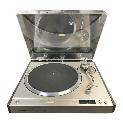
Pioneer PL-707 User manual

Service
c/Manual
CIRCUIT
&
MECHANISM
——
DESCRIPTIONS
in
.
RDER
NO.
REPAIR
&
ADJUSTMENTS
RHP
2
56-0
STEREO
TURNTABLE
L-70O7
MODEL
PL-707
COMES
IN
FOUR
VERSIONS
DISTINGUISHED
AS
FOLLOWS:
K
AC120V
only
U.S.A.
model
(Without
cartridge)
AC220V,
240V
(switchable)
United
Kingdom
model
AC110V,
120V,
220V,
240V
(switchable)
General
export
model
|
He
AC220V,
240V
(switchable)
European
continent
model
@
This
service
manual
is
applicable
to
the
KUT
type.
For
servicing
of
the
other
types,
please
refer
to
page
56.
©
Ce
manuel
d’instruction
se
refére
au
mode
de
réglage,
en
francais.
@
Este
manual
de
servicio
traat
del
método
de
ajuste
escrito
en
espajiol.
CONTENTS
1.
SPECIFICATIONS
..........
00000
c
ee
eee
2
10.
P.C.
BOARDS
CONNECTION
DIAGRAM
....
36
2.
FRONT
PANEL
FACILITIES.............
3
11.
SCHEMATIC
DIAGRAM
.............05-
39
3.
BLOCK
DIAGRAM
...............0005
5
12.
ELECTRICAL
PARTS
LIST..............
42
4.
MECHANISM
DESCRIPTION
...........-.
7
13.
TROUBLESHOOTING
............2.000.
44
5.
CIRCUIT
DESCRIPTIONS
...............
13
14.
ADJUSTMENTS
.............0
ccc
e
eee
50
6.
DISASSEMBLY
...........0..000eeeeee
23
REGLAGE
42d
catia
ena
ed
Seaawes
52
7.
PARTS
LOCATION
........0.
00
cee
eeee
27
BIUSTE:
vc
Son
ed
eo
wh
Oo
cary
aa
eas
54
8.
EXPLODED
VIEW
AND
PARTS
LIST......
29
15.
FOR
HE,HB
AND
S
TYPES
oo.
-
cece
eee
56
SB:
PACKING
|G.
cask
ob
ore
best
os
Sue
wes
35
16.
SAFETY
INFORMATION
.............--
58
PIONEER
ELECTRONIC
CORPORATION
4-1,
Meguro
1-Chome,
Meguro-ku,
Tokyo
153,
Japan
PIONEER
ELECTRONICS
(USA)
INC.
1925
E.
Dominguez
St.,
Long
Beach,
California
90810
U.S.A.
PIONEER
ELECTRONIC
(EUROPE)
N.V.
Keetbergiasn
1,2740
Beveren,
Belgium
PIONEER
ELECTRONICS
AUSTRALIA
PTY.
LTD.
178-184
Boundary
Road,
Braeside,
Victoria
3195,
Australia
FZ
©
APR.
1983
Printed
in
Japan
9)
’

1.
SPECIFICATIONS
Motor
and
Turntable
Drive
System
.0......ccceece
neces
een
seeeeseeceeeeeeseees
Direct-drive
Motor
.
Quartz
PLL
Hail
motor
Turntable
Platter
........
310
mm
diam.
aluminum
alloy
die-cast
Speeds
33-1/3
and
45
rpm
Wow
and
Flutter
..
Less than
*0.012%
(WRMS)
0.025%
(WRMS)
+
0.035%
WTD
Peak
(DIN)
Values
marked
with
an
‘’*”
designate
the
wow
and
flutter
for
motor,
and
do
not
include
the
cartridge
or
tonearm
load.
Signat-to-Noise-Ratio
..............06
More
than
80
dB
(DIN-B)
(with
Pioneer
cartridge
model
PC-6MC)
Tonearm
NY
PO:
iar
iiceeesanstcesetees
Static-balance
type,
Straight
pipe
arm
Effective
Arm
Length
-.
235
mm
OVEINANG
iiss
siicasccsceecatats
conned
decsuceseetbenavevdesees
15mm
Usable
Cartridge
Weight
...
3g
(min.)
to
8 g
(max.}
PC-6MC
Specifications
Type
...
Moving
coil
type
Stylus...
0.3x0.
7m
mil
diamond
(PN-6
MC)
Output
Voltage
oo.
cee
eceeeessanenneeneasanasaeeees
2.2mVv
(1
kHz,
§
cm/s
LAT.
Peak)
Tracking
Force
..........02..-2...c0eeee
ee
1.7
g
to
2.3
g
(proper
2g}
Frequency
Response
Recommended
Load
..
Weight
+
10
to
35,000
Hz
-
50kQ
Subfunctions
Auto
lead
in,
Auto
return,
Auto
cut,
Repeat,
Quick
play,
Quick
stop,
Anti-skating,
Arm
elevation,
Tracking-force
direct-read-
out,
Tonearm
height
adjusting
device
(+
3
mm},
Insulator
height
adjusting
device,
Free
stop
hinges.
Miscellaneous
Power
Requirements
HE,
HB,
HP
models
.20.......
cc.
eesceeenesee
eee
AC
220
V/240
V
(switchable),
50,
60
Hz
KUT,
KCT
models
AC
120
V,
60
Hz
S,S/G
models
................4
AC
110
V/120 V/220 V/240
V
(switchable),
50,
60
Hz
Power
Consumption
HE,
HB,
HP
models
.
OW
KUT,
KCT
models
.
10W
S,
S/G
models
....
a.
7W
Dimensions
...........c:0ccceeeees
460
(W)
x
164
(H)
x
409
(D)
mm
18-1/8
(W)
x
6-1/2
(H)
x
16-1/8
(D)
in.
WIGKt
oie.
cseediccueetestiagesseucesibandestesecess
8.1
kg/17
Ib
14
oz
Accessories
EP
Adapter
..
psveelaceniviseee
Macetisaentccatoned
Operating
instructions
tee
baal,
Catridge
mounting
parts
(For
KUT
and
KCT
models)
Serews:
(IL):
G%e5
at
aoe
iyo,
Deeg
aeh
o
hace
Gu
cea
2
Screws:
(M))
4
pis
Tak
GATE
Saw
eee
wae
edd
ee
ae
2
Screws
(S)
isco
ek
aS
whe
ba
ed
ok
Sew
Seale
2
Washers
ss
\hiciss
ce
gow
s
Rieriiede'e
Kegele
oe
ee
2
NUS
chic
oe
casas
uepehare
OA
on
eormeban
nna
2
2
NOTE:
Specifications
and
design
subject
to
possible
modification
without
-
notice,
due
to
improvements.

2.
FRONT
PANEL
FACILITIES
@
POWER
SWITCH
Press
this
switch
to
turn
the
power
on
and
off.
{ON}
(depressed
position)
:
Power
is
switched
ON.
{OFF]
{released
position)
:
Power
is
switched
OFF.
When
the
POWER
switch
is
set
to
ON,
the
following
swit-
ches
are
set
automatically.
¢
SPEED
switch
—
[33]
¢
RECORD
SIZE
switch
—
[30]
©
REPEAT
switch
—
[OFF]
=)
(eS)
©
~y
2
@)
«
ae
@
SPEED
SWITCH
Set
this
switch
in
accordance
with
the
speed
of
the
record
which
is
to
be
played.
[33]
indicator
lights:
For
playing
33-1/3
rpm
records.
[45]
indicator
lights:
For
playing
45
rpm
records.
@
RECORD
SIZE
SWITCH
Set
this
switch
in
accordance
with
the
size
of
the
record
which
is
to
be
played.
[12°30]
indicator
lights:
For
playing
30
cm
(12”}
records.
[10°25]
indicator
lights:
For
playing
25
cm
(10°)
records.
[7°17]
indicator
lights:
For
playing
17
cm
(7”)
records.
@
REPEAT
SWITCH
Press
this
switch
so
that
the
indicator
lights
for
repeat
play.
@
ARM
ELEVATION
SWITCH
¢
Use
the
switch
to
manual
play.
*
Use
the
switch
to
suspend
record
play
temporarily.
©
Use
the
switch
when
changing
the
tracks
during
manual
play.
{
¥
]
indicator
tights:
The
tonearm
rises
(the
styius
moves
away
from
the
record).
l
&
|
indicator
lights:
The
tonearm
descends
(the
stylus
is
lowered
onto
the
record).
@®©
START/STOP
SWITCH
Press
this
switch
when
starting
auto
play
or
when
stopping
play
@
QUARTZ
LOCK
INDICATOR
This
lights
when
the
platter
is
rotating
at
exactly
33-1/3
or
45
revolutions
per
minute.
SPEED
INDICATORS
(33,
45)
These
indicate
the
platter
speed.
(33]
lights:
Platter
is
rotating
at
33-1/3
rpm.
[45]
lights:
Platter
is
rotating
at
45
rpm.
@®
SIZE
INDICATORS
(30,
25, 17)
These
indicate
the
record
size.
{1230}
lights
—
30
cm
(12)
(10°25]
lights
—
25
cm
(10)
[7°17]
lights
—
17
cm
(7”)
REPEAT
INDICATOR
(REPEAT)
This
indicator
lights
up
when
the
repeat
play
function
is
utilized.
@
ARM
ELEVATION
INDICATOR
(
¥-¥
)
These
indicators
indicate
whether
the
tonearm
is
the
raised
(up)
or
jowered
(down)
position.
(
¥
J
lights:
The
tonearm
rises
(the
stylus
moves
away
from
the
record}.
[
&
}
lights:
The
tonearm
descends
(the
stylus
is
lowered
onto
the
record).
@
START/STOP
INDICATOR
This
lights
when
the
START/STOP
switch
has
been
pressed
and
auto
piay
has
been
started.
©
This
lights
when
the
START/STOP
switch
is
pressed
to
suspend
play.
@
CARTRIDGE
(PC-6MC)
NOTE:
A
cartridge
is
not
provided
with
the
KUT
and
KCT
models
and
so
your
own
cartridge
should
be
mounted,
following
the
instructions
laid
down
in
CARTRIDGE
MOUNTING.
@
HEADSHELL
@®
ANTI-SKATE
CONTROL
This
is
rotated
when
performing
the
anti-skating
adjustment.
ARM
REST
This
serves
to
hold
and
clamp
the
tonearm.
When
moving
the
tonearm,
release
the
clamp.
@
TONEARM
TRACKING
FORCE
ADJUSTMENT
WEIGHT
This
is
used
when
adjusting
the
tracking
force.
PLATTER
PLATTER
SHAFT
@
RUBBER
MAT
@
EP
ADAPTER
This
is
used
when
playing
records
without
a
“middle.”
@
CABINET
@
DUST
COVER

3.
BLOCK
DIAGRAM
PHONO
MOTOR
CONTROL
SECTION
WAVEFORMS
ING
THRU
@
ARE
PARSED
THROUGH
SUFFER
Aue,
Al1C1
PA2007
&21C2
PA2008
eee
TU
me
Let
APHASE
LB2
.
¢*)
)
Lat
Lae
*
7’
zav
"AIC
4
TD62503P!
.
2:
STANDARD
STANDARD
332¢rpm—-55.
Hz
45-om—~75Hz:
(QUARTZ
LOCK
SIGNAL
tovces
|
MOTOR
Con
r
33/45
GENERATOR
$A1C«
TOCTS03P
syle
asi
(QUARTZ
LOCK
SIGNA’
33/45,
STOP
SIGNAL’
TONEARM
SENSOR
SECTION
CONTROL
SECTION
TONEARM
MOTOR
DRIVE
SECTION
B:
IC:
PD6003
B:IC2
BAs208
ClICl
TCADIBP
POSITION
SENSOR
PHONO
8
Swt
MOTOR
stop
TONEARM
DRIVE
MOTOR
oe
aia
|
QUARTZ
LOCK
IND
@:04
|
sv
iy
as
ino
POWER
SUPPLY
SECTION
CONTROL
SWITCH
SECTION
*
;
|
B:1C3
r
soem
uPCTBMOSH
IND
G:
55:
SPEED
ae
25em
IND
288:
|
sw
is
"
dee
Vem
1
S40
SiZE
6
sw
ae
Hem
IND
—.
REP
H:S6:
REP
REP
sw
IND
REPEAT
IND
—
|
HOS?
EV
Ev
Sw
uP
IND
DOWN
IND
~—7
|
15
START/
STAAT/
5
C *
:
START/STOP
STOP
STOP
uP
IND
Laced
sw
IND
POWER
TRANSFORMER
START/STOP
IND
SWITCH
St:
Mtcro
ON:
OFF
S7
ARM
ELEVATION
UP--OOWN
NOTE
pease
Aas
Gee
Bie
erantseTor
ON-OFF
‘The
jtters
preceding
the
circuit
component
symbols
denote
the
unit
s
—
—
where
the
component
is
located.
2
POWER
OFF
$3:
PO
ON
OFF
A:
MOTOR
ASS‘Y
(PXM-175)
F.
ORIVER
(F}
ASS'Y
Sa:
SIZE
30cm
25m
-
Tew
‘The
uncerlined
rndicates
the
switch
position.
B
CONTROL
UNIT
(xwM.141)
G:
CONTROL
(A)
UNIT
6
epee
33410
asrpm
C:
PHOTO-TRANSISTOR
UNIT
(xwx-137)
{XWX-134)
O:
LED
UNIT
(xwx.1381
H:
CONTROL
(8)
UNIT
EPEAT
ON
OFF
S6
:
AEPE,
OFF
E
START
UNIT
(XWX-1361
(xwo-138)

PL-707
4.
MECHANISM
DESCRIPTION
To
facilitate
understanding
the
operation
of
the
PL-9,
the
total
unit
may
be
broken
down
into
blocks
consisting
of
the
tonearm
drive
mechanism,
the
sensing
mechanism
serving
to
sense
lead
in
and
lead
out
positions
of
the
tonearm,
the
control
section
consisting
of
the
full-auto
control
IC
PD6003,
and
the
motor
section
functioning
to
drive
the
turntable
platter.
>»
Trip
wheel
Switch
SW1
«
The
operational
and
functional
relationship
between
each
block
is
quite
complex,
so
in
order
to
understand
total
system
operation,
it
is
first
necessary
to
thoroughly
understand
the
operat-
ion
and
function
of
each
block,
then
carefully
study
their
interrelationships.
This
manual
covers
the
subject
in
that
order.
First,
the
operation
and
function
of
each
block
will
be
described,
then
a
timing
chart
is
presented
to
clarify
block
relationships.
Cam
(Sloping
area)
Worm-gear
Fig.
4-1
Tonearm
drive
mechanism
4.1
TONEARM
DRIVE
MECHANISM
1.
The
tonearm
drive
mechanism
consists
of
the
tonearm
drive
motor,
worm-gear,
gear
(A),
gear
(B),
trip
gear,
trip
wheel,
cam,
switch
SW1,
and
switch
SW2.
(Fig.
4-1)
2.
The
gear
cluster
is
shown
in
Fig.
4-2.
When
the
cam
is
held
immoveable
and
gear
(A)
is
rotated
in
a
counterclockwise
direction,
asmall
amount
of
friction
is
felt,
but
gear
(B)
and
trip
gear
also
rotate.
Note
that
rotation
of
the
trip
gear
also
rotates
the
trip
wheel.
(Fig.
4-3)
Also
note
that
when
the
cam
is
free
to
rotate,
friction
will
cause
it
to
rotate
in
the
same
direction
as
gear
(A)
and
(B).
8.
Refer
to
Fig.
44.
The
elevation
shaft
contacts
the
sloping
area
located
around
the
center
shaft
of
the
cam.
Also
note
the
position
of
the
cam
at
this
time.
This
is
the
position
the
mechanism
will
be
in
prior
to
starting
up
the
unit.
The
tonearm
will
be
on
the
arm
rest,
and
arm-elevation
will
be
in
the
DOWN
posit-
ion.
Center
shaft
Trip
wheel
Friction
plate
2
ae
Gear
(A)
i
Aisin
ai
omy
y
Fig.
4-2
Gear
cluster
Trip
wheel
YW
Prevent
the
cam
from
F
/
{uring
Fig.
4-3
Gear
cluster
operation

PL-707
Elevation
shaft
Sloping
area
Cam
Tonearm
shaft
Fig.
4-4
Lead
in
operation
Sloping
area
_|
<p
Elevation
shaft
Tonearm
shaft
Trip
wheel
\
Trip
gear
Fig.
4-5
Return
operation
4.
Turn
the
worm
gear
by
hand
imitating
what
would
occur
if
the
START/STOP
button
were
depressed
causing
the
motor
to
rotate
the
gear.
Worm
gear
rotation
causes
gear
(A)
to
rotate,
and
the
gears
shown
in
Fig.
4-2
and
4-3
of
item
2
above
all
turn
in
a
clockwise
direction.
5.
The
elevation
shaft
raises
as
the
gear/cam
assembly
rotates,
and
this
in
turn
causes
the
tonearm
to
raise.
The
two
switches,
SW2
and
SW1
are
also
tumed
OFF.
6.
As
the
assembly
rotates
further,
the
trip
wheel
and
PU
plate
attached
‘to
the
tonearm
shaft
come
into
contact,
creating
the
same
condition
as
occurred
in
item
2
where
the
cam
was
held
in
an
immoveable
position.
Continued
rotation
of
the
trip
wheel
causes
the
PU
plate
attached
to
the
tonearm
shaft
to
tum.
7.
Rotation
of
the
PU
plate
moves
the
tonearm
to
the
point
specified
by
the
sensing
and
control
mechanisms
(covered
in
the
following
paragraphs).
When
the
tonearm
reaches
that
specified
point,
the
motor
reverses
itself,
and
the
cam
switches
SW1
and
SW2
ON
in
sequence.
Arm-elevation
goes
to
the
DOWN
position
and
playback
starts.
8.
In
practice,
each
of
the
above
operational
steps
are
controlled
either
directly
or
indirectly
from
the
control
section
or
by
the
forward
or
reverse
rotation
of
the
motor.
The
control
section
picks
up
its
operational
cues
by
detect-
ing
the
ON
or
OFF
status
of
switch
SW1
and
SW2,
and
these
switches
are
controlled
by
the
movement
of
the
mechanism
positioning
the
cam.
4.2
SENSING
MECHANISM
As
shown
in
Fig.
4-6,
the
shutter
fixed
to
the
tonearm
is
positioned
to
travel
in
the
space
be-
tween
the
phototransistors
and
LEDs
mounted
on
Phototransistor
board
Phototransistor
>
S
>
End
sensor
(A),
(B)
ais
Lowering
position
detector
Shutter
Fig.
4-6
Sensing
mechanism
their
respective
boards.
The
shutter
has
three
0.7mm
slits
cut
out
of
its
outer
circumference
at
the
position
the
outer
edge
of
a
30cm,
25cm,
or
17cm
record
disc
would
be
located.
The
slit,
or
opening
located
inside
of
those
three
slits
is
the
end
sensor
slit
(Fig.
4-7).
Stit
(30
cm)
Slit
(25
em)
End
sensor
slit
Fig
4-7
Shutter
=
Lowering
Position
Detector
1.
This
unit
is
mechanically
designed
to
allow
the
shutter
to
pass
between
two
boards
mounting
the
sensing
elements
or
photocoupler.
The
photocoupler
consists
of
an
LED
and
photo-
transistor.
2.
The
shutter
moves
with
the
tonearm,
and
a
signal
is
transmitted
to
the
control
section
by
the
light
emitted
from
the
LED
(normally
interrupted
by
the
opaque
portion
of
the
shutter)
being
passed
through
the
30cm,
25cm,
or
17cm
slit
and
triggering
the
pho-
totransistor
ON.
Function
End
Sensor
As
the
tonearm
travels
toward
the
inside
of
the
record
disc
and
reaches
the
end
sensor
zone
(end
sensor
slit),
the
light
transmitted
by
the
LED
is
passed
through
the
end
sensor
slit
and
turns
the
phototransistor
ON,
then
OFF.
This
causes
the
pulse
signal
transmitted
by
end
sensor
A
and
B
to
go
90°
out
of
phase.
2.
The
pulse
frequency
is
compared
with
the
rotational
speed
(movement)
of
the
tonearm,
and
then
sent
to
the
control
section
as
the
re-
cord
disc
lead-out
groove
sensor
signal.
i
Arm
Rest
Position
Sensor
When
the
three
sensors
consisting
of
the
lower-
ing
position
sensor
and
end
sensor
(A)
and
(B)
are
all
simultaneously
picking
up
transmit-
ted
light,
control
determines
that
the
tonearm
is
at
the
arm
rest
position.
2.
This
status
is
used
to
control
starting
and
stopping
of
the
turntable
motor
during
manual
operations,
or,
in
the
auto-return
mode,
simply
perceives
that
the
tonearm
has
returned
to
the
arm
rest.
He
Function
Repeat
display
output
CW
rotation
output
{EV-UP
display
output
START-STOP
display
output
SW2
input
Speed
selector
output
Turntable
motor
stop
output
Ryo
.
|30cm
display
output
25cm
display
output
Size
selector
switch
input
R.
:
|17em
display
output
End
sensor
B
input
End
sensor
A
input
R,
[Repeat
switch
input
Lowering
position
sensor
input!
T
R,
|
EV
switch
input
22
R.
|
START-STOP
switch
input
{
|
‘
i
R,
R.
|Speed
selector
switch
input
tC
PD6003
pins
R, R.
|
CCW
rotation
output
PD6003
Pin
Function
Table
Fig.
4-8
PD6003

;
PL-707
4.3
CONTROL
SECTION
The
functions
of
the
full-auto
control
IC
PD6003
are
described
in
this
section.
The
table
shown
in
Fig.
4-8
lists
the
function
performed
by
each
pin
of
PD6003.
Please
refer
to
this
table
as
the
detailed
explanation
progresses.
1.
When
the
tonearm
is
at
the
arm
rest
position,
pressing
the
START/STOP
button
causes
the
turntable
motor
to
start
rotating
and
illumin-
ates
the
LED
built
into
the
START/STOP
button
and
the
EV
UP
display
LED.
At
the
same
time
the
tonearm
drive
motor
moves
the
tonearm
toward
the
lead
in
groove
of
the
record.
The
tonearm
drive
motor
continues
rotating
until
it
reaches
the
point
where
the
signal
from
the
lowering
position
sensor
is
picked
up.
When
that
point
is
reached,
the
drive
motor
is
reversed,
lowering
the
tonearm.
End
sensor
A
and
B
is
used
to
detect
the
end
of
playback,
but
if
the
START/STOP
button
is
depressed
during
playback,
the
tonearm
drive
motor
starts
rotating
in
the
return
direction
and
tonearm
returm
operation
is
started.
When
the
tonearm
reaches
the
point
directly
above
the
arm
rest,
the
tonearm
drive
motor
starts
rotating
in
the
reverse
direction
and
lowers
the
tonearm
on
the
arm
rest.
If
the
operation
in
the
above
step
is
carried
out
with
the
repeat
switch
ON,
the
tonearm
again
will
returm
to
the
lead
in
groove.
If
the
repeat
switch
is
OFF,
the
tumtable
motor
will
stop
at
this
point.
4.4
ACTUAL
OPERATION
(PLAYBACK
OF
A
1.
2.
10
33
rpm,
17cm
RECORD
DISC)
Automatic
Lead
in
Depress
the
button
and
turn
the
power
switch
ON.
Set
the
speed
for
the
record
to
be
played
(33
rpm).
When
the
33
rpm
button
is
depressed,
an
instruction
signal
from
the
motor
assembly
will
illuminate
the
33
rpm
display
LED,
D22.
Next,
set
the
proper
size
for
the
record
to
be
played
(17cm
in
this
case).
When
the
size
selector
switch
is
depressed
twice,
the
11
pin
of
PD6003
will
go
to
a
low
level,
and
the
17cm
display
LED,
D26
will
be
illuminated.
With
the
turntable
thus
set
up,
depressing
the
START/STOP
button
causes
the
15
pin
of
PD6003
to
go
to
a
low
level.
Also
6
pin
goes
to
a
low
level,
illuminating
the
START/
STOP
display
LED,
D30.
At
the
same
time,
pin
17
goes
to
a
low
level
and
pin
18
goes
high,
starting
rotation
of
the
tonearm
drive
motor
in
the
mechanism
section.
The
worm
gear
is
coupled
to
the
rotating
motor
by
belt,
and
the
worm
gear
turns
gear
(A)
(and
cam)
in
a
clockwise
direction.
The
tonearm
is
lifted
by
the
arm-elevation
mech-
anism,
and
switch
SW2
and
SW1
go
OFF.
Gear
(A)
(and
the
cam)
continue
rotating
until
finally,
the
cam
makes
contact
with
the
PU
plate
fixed
to
the
tonearm
shaft.
When
the
cam
contacts
the
PU
plate,
it
stops
rotating.
However,
the
trip
wheel
continues
rotation
along
with
gear
(B).
Fig.
4-9
Mechanism
section
The
trip
wheel
is
making
contact
with
the
arm
rotation
stopper,
and
the
rotating
trip
wheel
causes
the
PU
plate
to
turn.
The
tuming
PU
plate
moves
the
tonearm
toward
the
center
of
the
platter.
As
the
tonearm
moves,
so
does
the
shutter
attached
to
the
tonearm
shaft.
The
tonearm
(and
shutter)
go
past
the
30cm
and
25cm
lowering
position
until
it
reaches
the
17cm
record
disc
lead-in
groove
where
the
third
pulse
signal
from
the
lowering
position
sensor
{light
from
LED
passes
through
the
slit
in
the
shutter
fixed
to
tonearm
shaft
turning
pho-
totransistor
ON)
causes
the
26
pin
of
PD6003
to
go
to
a
low
level.
(Pulse
signals
are
also
produced
at
30cm
and
25cm
positions.)
10.
This
causes
the
PD6003
17
pin
to
go
low,
and
the
18
pin
to
go
to
a
high
level,
and
after
the
tonearm
drive
motor
stops,
it
commences
reverse
rotation.
As
it
rotates,
the
arm-elevat-
ion
shaft
riding
on
the
sloping
area
of
the
cam
moves
down
off
the
slope
and
playback
starts.
When
the
tonearm
drive
motor
rotating
in
re-
verse
(switch
SW1
ON)
tums
switch
SW2
ON,
the
PD6003
6
pin
goes
to
a
high
level,
extin-
guishing
the
START/STOP
display
LED,
D30.
The
tumtable
will
not
go
into
the
auto-stop
until
the
START/STOP
display
LED
is
ex-
tinguished
even
though
the
START/STOP
button
is
depressed.
Also,
when
both
the
tonearm
dirve
motor
and
switch
SW2
are
ON,
PD6003
17
and
18
pin
both
go
high,
stopping
the
drive
motor.
If
the
tonearm
does
not
move
off the
arm
rest
within
8
seconds
after
the
START/STOP
button
is
depressed
(tonearm
clamped
in
arm
rest),
the
START/STOP
display
indicator
starts
flashing.
If
this
status
(flashing)
continues
for
another
11
seconds,
the
start
instruction
is
cancelled
and
the
tonearm
lowers
in
the
arm
rest.
The
elevation
-up
display
LED,
D28
illuminates
when
the
START/STOP
button
is
depressed,
and
when
the
tonearm
moves
to
the
record
disc
and
lowers
down,
D14
is
extinguished.
PD6003
senses
the
first
pulse
as
the
30cm
position,
the
second
as
the
25cm,
and
the
third
as
the
17cm
record
size
position.
When
it
determines
that
the
tonearm
has
reached
the
proper
lowering
position,
pin
5
goes
to
a
high
level,
extinguishing
the
display.
Switch
SW2
Switch
SW1
vee
Gear
(A)
Fig.
4-10
Switch
SW1,
2
position
PL-707
Arm-elevation
UP
and
DOWN
.
When
the
arm-elevation
switch
is
depressed
during
record
playback,
arm-elevation
goes
UP
and
playback
is
temporarily
stopped.
When
the
arm-elevation
switch
is
depressed,
the
13
pin
of
PD6003
goes
to
a
low
level.
Pin
5
also
goes
low,
and
illuminating
the
elevation
display
LED,
D28.
At
the
same
time,
pin
17
goes
to
a
low
level
and
pin
18
goes
high,
starting
tonearm
drive
motor
rotation.
This
causes
the
cam
to
turn,
and
the
elevation
shaft
to
ride
up
on
the
slop-
ing
section
of
the
cam.
This
action
causes
the
arm-elevation
to
go
to
the
UP
position,
stop-
ping
record
playback.
:
The
tonearm
drive
motor
continues
to
move
the
cam
until
the
position
is
reached
where
SW1
is
turned
OFF
(tonearm
still
in
UP
posit-
ion).
To
restart
playback,
the
arm-elevation
switch
is
depressed
again.
This
causes
the
13
pin
of
PD6003
to
go
to
a
low
level.
The
5
pin
goes
high,
extinguishing
the
elevation
display
LED,
D14.
At
the
same
time,
pin
17
goes
high
and
pin
18
goes
low,
causing
the
tonearm
drive
motor
to
rotate
in
an
opposite
direction
of
that
in
the
UP
position.
As
the
cam
turns,
the
elevat-
ion
shaft
drops
down
off
the
slope,
lowering
the
tonearm
and
starting
playback
again.
The
tonearm
drive
motor
continues
to
move
the
cam
until
the
position
is
reached
where
SW2
is
turned
ON
(tonearm
still
in
DOWN
position).
i
(signal
pin
from
lowering
position
sensor)
For
manual
playback
operation,
depress
the
arm-elevation
switch
to
raise
the
tonearm
up
off
the
arm
rest
(UP),
then
move
it
to
the
desired
point
over
the
record
by
hand.
De-
pressing
the
arm-elevation
switch
again
will
then
lower
(DOWN)
the
tonearm
onto
the
re-
cord.
Operationally,
this
follows
the
se
quence
listed
in
items
2
through
7
above.
Also
during
manual
play,
when
the
tone-
arm
is
manually
moved
toward
the
center
of
the
record
(off
the
arm
rest),
the
platter
commences
rotation.
When
the
tonearm
is
moved
off
the
arm
rest,
PD6003
26
pin
goes
to
a
high
level,
and
the
8
pin
goes
to
a
low
level,
starting
the
motor
rotation.
414

PL-707
=
Auto-return
1.
When
record
playback
is
over,
the
tonearm
stylus
goes
from
the
band
of
audio
grooves
into
the
lead
out
groove,
and
the
pulse
width
of
the
signal
output
from
end
sensor
A
and
B
become
more
narrow.
This
informs
PD6003
that
record
playback
has
ended.
The
phase
of
the
pulse
from
end
sensor
A
and
B
is
set
so
that
B
leads
A
by
90°,
however
this
phase
offset
is
not
used
for
detection
of
the
end
of
playback,
but
to
prevent
any
unintentional
operations
from
sources
such
as
record
disc
eccentricity.
2.
When
playback
completion
is
detected,
PD6003
pin
17
goes
to
a
high
level
and
pin
18
goes
low,
starting
the
tonearm
drive
motor
rotating.
As
rotation
moves
the
cam,
the
slope
causes
the
arm-elevation
to
go
UP,
raising
the
tonearm.
3.
As
the
cam
continues
rotating,
it
strikes
the
PU
plate.
This
stops
cam
movement,
but
the
trip
wheel
continues
rotating
and
turns
the
PU
plate.
This
results
in
the
tonearm
being
return-
ed
to
a
position
above
the
arm
rest.
4.
At
this
position,
light
strikes
the
lowering
position
detector
and
end
sensor
A
and
B
(all
three
at
once),
and
pin
24,
25,
and
26
of
PD6003
go
to
a
low
level.
5.
One
to
two
seconds
later,
PD6003
pin
17
goes
low
and
pin
18
goes
high,
and
after
the
tone-
arm
drive
motor
stops,
it
reverses
rotation
and
sends
the
arm-elevation
back
down
the
cam
slope.
This
lowers
the
tonearm
on
the
arm
rest
ending
playback.
5
6.
At
the
same
time,
the
cam
tums
switch
SW1
ON
(switch
SW2
is
already
ON).
When
both
switches
come
ON,
both
pin
17
and
18
(PD6003)
go
to
a
high
level,
stopping
the
tonearm
drive
motor.
Also,
when
the
tonearm
reaches
the
arm
rest
position,
pin
8
goes
high,
lowering
the
tonearm
and
causing
pin
5
to
go
high.
This
causes
the
platter
to
stop
rotating
and
extinguishes
the
elevation-up
display
LED,
D28.
12
Auto-stop
When
it
is
desired
to
stop
record
playback
in
the
middle
of
the
record, depress
the
START/
STOP
button.
As
the
START/STOP
button
is
depressed,
PD6003
pin
15
goes
to
a
low
level.
Pin
17
goes
high
and
pin
18
goes
low,
starting
rotation
of
the
tonearm
drive
motor.
Rotation
causes
the
arm-elevation
to
ride
up
on
the
slope
of
the
turning
cam
raising
the
tonearm.
Also
6
pin
goes
to
a
low
level,
thereby
illumi-
nating
the
START/STOP
display
LED,
D30.
From
here
the
operation
is
the
same
as
that
for
auto-return
(above),
items
3
through
6.
The
START/STOP
display
LED,
D30
are
extinguished
by
the
tonearm
drive
motor
reversing
rotation
and
tuming
switch
SW1
ON
and
sending
PD6003
pin
6
to
a
high
level.
Auto-repeat
To
repeat
playback
of
the
same
record,
depress
the
repeat
button.
This
causes
PD6003
pin
12
to
go
to
a
low
level.
At
the
same
time,
pin
4
also
goes
low,
illuminating
the
repeat
display
LED,
D27.
When
the
repeat
button
has
been
depressed,
after
autoretum
operations
have
returned
and
lowered
the
tonearm
on
the
arm
rest,
the
unit
again
goes
into
autolead
in
operations
and
continues
playback.
(The
platter
motor
con-
tinues
to
rotate.)
5.
CIRCUIT
DESCRIPTIONS
5.1
SIMPLE
SIGNAL
PATH
The
PL-707
motor
drive
circuit
consists
of
the
control
IC
PA2007,
reference
phase
generator
IC
PD1003,
motor
drive
IC
PA2008,
and
IC
TD62504P
functioning
to
produce
the
various
operational
switch
signals.
The
signal
picked
up
from
the
speed
sensor
section
is
amplified
by
the
FG
amp,
then
convert-
ed
to
the
speed
sensor
signal
voltage
(DC)
by
the
F/V
converter.
Reference
phase
voltage
is
obtained
by
extract-
ing
the
reference
phase
from
PD1003
pin
15,
pass-
ing
it
through
the
1/2
divider,
then
sending
it
through
the
P/V
converter
to
be
used
as
reference
phase
voltage
(DC).
The
speed
sensor
signal
voltage
and
reference
phase
voltage
are
each
passed
through
a
buffer
amp
and
resistance
and
combined
(compared).
The
resulting
voltage
is
taken
from
the
IC
PA2008
pin
6
and
input
into
the
absolute
value
amp,
and
is
used
to
contro]
the
4-phase
drive
circuit
motor
rotation
voltage,
maintaining
the
motor
at
a
fixed
speed.
5.2
SPEED
SENSOR
SECTION
1.
The
speed
sensor
board
consists
of
a
single
printed
circuit.
2.
Above
this,
rotates
a
rotor
with
400
magnet-
ized
poles
on
its
lower
face.
Output
varies
in
accordance
with
the
rotational
speed
of
the
rotor.
3.
The
output
(frequency)
from
the
speed
sensor
board
is
111Hz
for
33
1/3
rpm
and
150Hz
for
45
rpm.
4,
The
output
signal
is
sent
to
PA2007
as
a
balanced
input.
5.3
FG
AMP
In
order
to
square
the
waveform
of
the
signal
obtained
from
the
speed
sensor
section
(output:
0.5
—
2.0
mV
rms)
prior
to
inputting
it
into
the
F/V
converter,
it
is
amplified
69dB
across
a
band
width
of
20
to
160Hz.
5.4
F/V
CONVERTER
1.
Since
the
rotational
speed
is
detected
at
a
fixed
frequency,
the
frequency
must
be
converted
to
a
voltage
(DC).
This
function
is
performed
by
the
F/V
converter.
2.
Previously
(in
PA2004)
this
was
done
by
a
2-frequency
F/V
converter,
however,
increasing
control
gain
of
PA2007
allows
a
signa!-frequen-
cy
F/V
to
be
used.
PL-707
3.
F/V
converter
gain
does
not
change
even
with
rpm
changes.
4.
Switching
reference
frequency
is
shown
in
Fig.
5-1.
When
the
switch
is
OFF,
speed
is
set
to
33
1/3
rpm,
and
when
the
switch
is
ON,
the
variable
resistor
used
by
33
1/3
rpm
is
connected
parallel
to
the
45
rpm
variable
resistor.
The
resulting
total
impedance
establishes
rotat-
ional
speed.
Thus,
each
time
33
1/3
rpm
is
adjusted,
45
rpm
must
also
be
adjusted.
This
arrangement
prevents
any
rotational
instabi-
lity
that
might
result
from
both
switches
being
temporarily
OF
F
when
speed
changes
are
made
by
switching
from
33
1/3
—
45
rpm.
5.
Co,
Ct,
Rt,
and
Rfv
are
each
connected
to
ground,
but
the
grounding
point
is
very
close
to
that
of
PA2007.
Also,
Rt
is
a
0.01
uF
ceramic
capacitor
for
noise
and
oscillation
removal,
and
it
is
grounded
in
close
prox-
imity
to
PA2007
too.
Rt
45
r.p.m
33
1/3
r.p.m
ay
Fig.
5-1
Switching
reference
frequency
5.5
REFERENCE
PHASE
GENERATOR
IC
PD1003
1.
When
power
is
tumed
ON,
the
X’tal
oscillator
block
generates
a
6.144
MHz
signal
by
using
the
externally
connected
crystal
oscillator.
2.
This
is
reduced
to
6kHz
by
divider
circuit
1
(1/1024),
then
this
divided
signal
is
input
to
divider
circuit
2.
3.
The
6kHz
signal
input
to
divider
circuit
2
is
further
divided
1/27
for
33
1/3
rpm
operation,
and
1/20
for
45
rpm,
then
transmitted
from
pin
15
to
PA2007
pin
8.
331/3
rpm:
222.2Hz
45
rpm:
300Hz
13

PL-707
5.6
1/2
DIVIDER
AND
P/V
CONVERTER
The
signal
received
at
the
8
pin
(item
above)
is
Nom)
Phase-locked
area
further
divided
by
1/2
by
the
1/2
divider,
then
input
to
the
P/V
converter.
The
P/V
converter
serves
to
convert
the
reference
phase
taken
from
the
1/2
divider
to
DC
voltage.
Ne
The
reference
phase
converted
into
DC
voltage
is
combined
(by
the
buffer
amp
and
resistor)
with
the
DC
voltage
from
the
F/V
converter
(and
used
for
rotation
speed)
and
transmitted
from
pin
11
as
a
motor
rotation
speed
control,
signal
to
IC
PA2008
pin
6,
then
finally
to
the
absolute
value
amp
(Fig.
5-2).
F-V
Rt
10k
Vout
P-Vv
Fig.
5-2
(F—V)
+
(PV)
circuit
F-v
output
—~
ret
Phase-locked
area
discrimination
threshold
Vo
ier
——=
f(z)
Fig.
5-4
F/V
converter
output
F-Vour
LOCK
LED
Fig,
5-5
Phase-locked
discrimination
theoretical
circuit
5.7
PHASE-LOCK
DISCRIMINATOR
CIRCUIT
When
phase
control
is
in
effect,
the
output
characteristics
of
the
F/V
converter
appear
as
in
Fig.
5-3.
The
portion
that
shows
no
change
in 1.
speed
when
load
torque
is
varied
up
and
down
can
be
considered
as
the
phase-locked
area,
and
the
portion
where
large
rotational
speed
changes
occur
(as
in
Fig.
5-4)
is
outside
the
phase-locked
area.
Thus,
F/V
converter
output
can
be
input
into
2
an
absolute
value
comparator
having
an
upper
and
lower
threshold.
A
theoretical
diagram
of
such
acircuit
is
shown
in
Fig.
5-5.
Noise
(Vout)
8.0
/
Vref
=
5.0
Operating
point
3.5
to
(Hz)
Noise
Fig.
5-3
Input/output
characteristics
5.8
STOP
DISCRIMINATOR
CIRCUIT
Depressing
the
START/STOP
button
of
the
PL-707
transmits
a
stop
signal
generating
a
reverse
torque
and
applying
a
brake
to
the
motor.
Motor
rotation
stops
almost
immedi-
ately.
The
stop
discriminator
circuit
functions
to
detect
low
or
high
rotation
speed
through
the
charge/discharge
status
of
capacitors
and
resistors
connected
to
IC
PA2007
pin
10
(To/STOP),
and
when
rotation
drops
below
a
certain
speed,
motor
torque
is
dropped
to
zero.
A
theoretical
circuit
diagram
is
shown
in
Fig.
5-6.
After
that,
the
platter
turns
a
small
amount
due
to
inertia,
then
stops.
R/S
FF
}
Normally
mon-conducting
»az008
—
TD62503P
H
stary/
pa2007
Stop
discriminator
circuit
Comparator
reference
voltage
f
av
ND
PAZO08
Absolute
vaiue
amp
Fig.
5-6
Stop
discriminator
theoretical
circuit
5.9
ABSOLUTE
VALUE
AMP
AND
ROTAT-
ION
DIRECTION INDICATOR
CIRCUIT
1.
The
signal
at
the
6
pin
(control
input)
is
com-
pared
with
the
signal
at
the
5
pin
(reference
voltage)
and
the
difference
in
voltage
is
used
to
generate
current
in
the
motor
winding.
The
input/output
characteristics
are
shown
in
Fig.
5-7.
2.
The
control
input
is
higher
than
the
reference
voltage
(Vref
5V)
when
the
rotation
of
the
platter
is
higher
than
specified
speed.
When
this
occurs,
the
absolute
value
amp
sends
an
indication
(instruction)
to
the
rotation
direct-
ion
indicator
circuit
to
generate
reverse
torque
in
order
to
drop
the
speed
of
the
motor.
3.
The
control
input
is
lower
than
the
reference
voltage
(Vref
5V)
when
the
rotation
of
the
platter
is
lower
than
specified
speed.
When
this
occurs,
the
absolute
value
amp
sends
an
indication
(instruction)
to
the
rotation
direct-
ion
indicator
circuit
to
generate
forward
torque
in
order
to
increase
the
speed
of
the
motor.
control
current
Reverse
torque
region
|
Forward
torque
region
No-load
operating
No-load
operating
point
:
point
{
Vref
-—Vin)
Fig.
5-7
Input/output
characteristics
5.10
DRIVE
CIRCUIT
1.
The
HA
and
HB
Hall
elements
(6
magnetized
pole
pieces
fixed
to
the
circumference
of
the
motor)
are
attached
electrically
90°
out
of
Phase
with
each
other.
These
elements
are
used
to
sense
the
rotational
position
of
the
motor.
2.
The
position
sensing
signal
produced
by
the
Hall
elements
are
each
output
to
the
block
diagram
position
signal
synthesizing
circuit,
and
their
waveforms
are
shaped
as
shown
in
Fig.
5-8.
3.
The
staircase
waves
are
each
input
into
the
block
diagram
4-phase
drive
circuit,
and
as
shown
in
Fig.
5-8,
LA
and
LB
alternate
back
and
forth
in
a
90°
duty
cycle
(voltage)
to
turn
the
motor.
4.
LA
and
LB
amplitude
is
in
proportion
to
the
output
of
the
absolute
value
amp.
90°|
90°{
90
Ha
48
Fig.
5-8
Drive
circuit
waveforms
15

PL-707
5.
1.
18
11
REVERSE
ROTATION
SENSING
CIRCUIT
The
motor
used
in
the
PL-9
is
the
dual-direct-
ion
drive
circuit
type,
and
if
manually
forced
in
the
reverse
direction,
it
will
continue
to
apply
a
forward
torque
in
an
attempt
to
restore
forward
rotation
as
long
as
it
does
not
exceed
specified
rotation
speed.
However,
when
reverse
rotation
exceeds
45
or
33
1/3
rpm,
the
rotation
direction
indicator
circuit
detects
this
as
an
overrun
in
the
forward
direction
and
applies
reverse
torque
in
an
attempt
to
bring
it
to
specified
rotation
speed.
Reverse
torque
applied
to
the
platter
already
rotating
in
reverse
will
further
increase
the
speed
and
the
turntable
will
run
out
of
control.
The
reverse
rotation
guard
circuit
prevents
the
platter
from
running
out
of
control.
The
equivalent
circuit
of
the
reverse
rotation
sensing
circuit
consists
of
a
D
type
flip-flop
(D
input
output
at
Q
by
CK
triggering).
Dtype
FF
Absolute
value
amp
Both
directions
Singie
direction
Fig.
5-9
Reverse
rotation
sensor
equivalent
circuit
Motor
current
control
Control
current
Reverse
torque
Forward
torque
Forward
direction
mode
Le
aE
rl
ele
eit
Triggering
edge
Pes
eas
OH
ter
Both
directions
operating
L
Fig.
5-10
Forward
direction
mode
Contro!
current
Forward
rque
Reverse
torq
torque
Reverse
direction
mode
—_—-
ee
ee
pe
galerie
ax
One
side
directions
operating
‘
Fig.
5-11
Reverse
direction
mode

PL-707
#
TIMING
CHART
1
Operational
sequence
for
a
single
cycle
between
power
ON
and
auto-
matic
stop
(full-automatic
operation,
17cm
record
disc).
.
:
B
Partially
DOWN
8
In
lead
in
zone
€
Partial
return
When
power
is
turned
ON,
the
(partially
UP)
(tonearm
UP}
6
On
arm
rest—-DOWN
unit
may
be
in
one
of
four
/_
up
/
wp
(normal
state)
aP
states
(@
~
@)
depending
on
1a
a
_
the
status
at
the
time
power
was
Ei
Down
eae
Lowering
previously
turned
OFF.
,
Arm
rest
Start
Arm
rest
position
End
sensor
Arm
rest
|_|
|
|
|
}
|
|
|
POWER
DOWN
POWER
UP
POWER
{DOWN
DOWN
POWER
uP
ue
DOWN
DOWN
UP
—
UP
DOWN
DOWN
uP
soUP.
COWN
DOWN
ON
Complete
ON
Complete
ON
i
Start
Complete
Start
plots
Start
Compiete
Start
Complete
Start
Complete
Start
Compiete
Start
Complete
Power
ON
Elevation
Auto-return
P06003
(IC)
No
PD6003(iCt)
terminal
name
~~
)
EV-UP
display
output
®
int
START/STOP
displ
Say
pose
"
|
=
—
a
-—
isplay
output;
@
F
7
,
ee
eon
mre
ulon!
<7
ae
—
7
:
-
ry
a
[sw
on
|
EV
switch
input
9
|
sw,
ae
sm)
ut
f
sw
on
i
On
(a
0N
ton
as
foment
START/STOP
switch
input
|:
eae
°
ft
i
eens
ae
‘
SS
oes
L
rT
CCW
rotation
output
L
i
L
ie
———
PET
RENE
OS
pote
Ba6208(
1C2)
:
BAG208(
1C2)
BaA6208('C2}
:
H
Hi
|
|
TIOIG,
3
kK
1S
2
7
3
18
a
CCW
=
OCC
—
ccw
wa:
see
LE
Sion
TIE
‘Stop
CWT
Sh
COM
_
|
Motor
rotation
direction
i
cw
;
cw
>
cw
>
"
CW
*
+
*
n
{
{
pee
:
'
!
Hl
i
! i
'
,
j
+
H(SW
OFF)
:
;
Ho
it
+
a
i
"
mes
ina
ee
-
Lisw
on)
5
ON
i
a
he
ae
eae
.
.
LED
EES
RC
ET
;
am
|
H(SW
OFF)
(SW
Dee
a
4
:
-
+
=
SW2
input
ae
(eWeGn)
rigw
on)
|
|
Sw
ON
|
|SWOFF
|
i
ia
ae
ee
es
!
bs
{
RTE
CIS
CER
RS CR
EET
a
Ei
:
8
4
H
H
a
RCTS
LSAT
EAPO
MA
ECE
SS
PCE
RN
(PRT
O
MERE
[eT]
CS
|
nd
sensor
B
input
x
:
On
rest
:
DS
ara
Se
a
SR GN
(Na
Baia
L
Off
rest
rest
|_—_____________,
aS
RSS|
SE
PAE
PD
(Lae
rae
DET
eareas
CERI!
MGR)
2
;
4
H
H
a
ReSRTSENS
t
(E
a
ers
ME
SIP
SNE
UIERS
TARTU
CERIN
NCSA
meer
eR
AN
RARE
|
End
sensor
Ainput
|
@
|"
[
onrest
:
ee
eae
|
Lowring
position
®
H 4
Tp
IK
=
'
Ss
Oe
ee
Se
ae
tenor
input
:
a
ee
eee
if
T
it
eae
Se
|
Lowering
Arm
at
ci
i
rest
position
End
sensor
Arm
rest
U1
POWER
DOWN
POWER
uP
POWER
DOWN
DOWN
DOWN
UP
UP
DOWN DOWN
UP UP
DOWN
DOWN
UP
UP
DOWN
DOWN
ON
Complete
ON
Comptete
ON
Start
Complete
Start
Complete
Start
Complete
Start
Com-
Start
Complete
Start
Complete
Start
Complete
Plete
17
18

®
TIMING
CHART
2
Operational
sequence
for
a
single
cycle
between
power
ON
and
auto-
matic
stop
(full-automatic
operation,
17cm
record
disc).
&
Partially
DOWN
6
In
lead
in
zone
€
Partial
return
On
arm
rest
DOWN
When
power
is
turned
ON,
the
(partially
UP)
{tonearm
UP)
{normal
state)
unit
may
be
in
one
of
four
er
fe
uP uP
states
(@
~
©)
depending
on
/
joa
~~
Pe
Te
le
ns
OR,
a
aa,
Bi
the
status
at
the
time
power
was
Gl
DOWN
Ta
Down
Lowering
previously
turned
OFF.
|
Arm
‘a
car
Arm
rest
tng
,
End
sensor
Arm
rest
POWER
DOWN
POWER
UP
POWER
DOWN
DOWN
baw
uP
Gam.
DOWN
DOWN
UP
ee
DOWN
DOWN
uP UP
ae
eclvis
jStart
Complete
Start
pete
Start
Complete
Start
Complete
Start
Complete
Elevation
Playback
Auto-return
Lead
in
|
|
|
Playback
1 1
'
ON
Complete
ON
Complete
ON
Start
Complete
Start
plete
!
|
Power
ON
|
|
P06003(IC1)
argh
terminal
name
No
Platter
motor
rotation
Vec
(Q3
OUT)
%
Platter
motor
stop
output
=
|
|
8
Repeat
switch
input
i
®
%)
%
epee,
eegget
hn
es
H
H
—.
_
H
‘iter
a
=
ite
tiem
Seen
eae
a
es
ao
aa
a
ee
re
al
ieee
(Light)
L(Light)
30cm
display
output
H
#
H
25cm
display
output
ne
ORs
ome
L
(Light)
Si
ers
oe
ae
G
17cm
dipslay
output
Pineal
op
eae
ee
L{
bight)
rea
eae
t
(Light)
t
{
*
-
*
{
LCSW
ON}
+
Lisw
Sn
ease
uCsw
ON)
>
4
_—_——__+
eS
+
at
eae
Geese
Le
a
ee
L(45:pm)
:
L.(45rpm).
(45pm).
en
a
Speed
selector
switch
input
Speed
selector
switch
output
|
@
—
wn
;
a
EES
PERRET:
SAE
33rpm
display
L
(Light)
jenna
—
LE
(Light)
(Light)
—
‘
45rpm
display
u(Light)—t
;
L
(Light)
.
i
en
ae
———
oS
or
:
t
I
i
!
|
i
:
|
i
!
'
i
i
A
:
i
i
not
‘
Lowering
|
;
t
i
i
i
|
Arm
|
i
Start
Arm
rest
position
|
|
;
|
'
End
sensor
|
Arm
rest
;
i ;
add
:
!
i
\
|
i
i |
|
|
|
‘ i
i
i
POWER
DOWN
POWER
UP
POWER
DOWN
DOWN
DOWN
UP
uP
DOWN
DOWN
UP
ouP
DOWN
DOWN
:
UP
UP
DOWN
BOW
ON
Complete
ON
Complete
ON
Start
Complete
Start
Complete
Start
Complete
Start
Com-
Start
Complete
Start
Complete
Start
Complete
plete
413
20

PL-707
=
TIMING
CHART
3
Operational
sequence
for
a
single
cycle
between
power
ON
and
auto-
matic
stop
(full-automatic
operation,
17cm
record
disc).
When
power
is
turned
ON,
the
unit
may
be
in
one
of
four
states
(@
~
©)
depending
on
the
status
at
the
time
power
was
A
Partially
Gin
lead
in
zone
€
Partial
return
On
arm
rest-DOWN
DOWN
(tonearm
UP)
(normal
state)
(partially
UP)
Lowering
7
previously
tumed
OFF.
Arm
rest
;
Start
Arm
rest
—_
position
End
sensor
Arm
rest
!
it
[+
DOWN
DOWN
DOWN
UP
POWER
DOWN
DOWN
DOWN
uP
soup
DOWN DOWN
uP
=
UP.
DOWN
DOWN
UP
—suP
DOWN DOWN
ON
Complete
ON
Complete
ON
Start
Complate
Start
Complete
Start
Compiete
Start
Complete
Start
Complete
Start
Complete
Start
Compiete
—_—
POWER
ON
Lead
in
Elevation
End
zone
Auto-retum
POWER
ON
Actual
mechanism
operation
T
re
a
ns
ed
en
|
START
button
ON
|
Trip
wheel
starts
During
playback
or
|
|
(elevation
UP)
on
arm
rest
(stop)
*
|
Auto-return
sensor
Trip
wheel
i
T
:
|
Toarm
rest
i
Operation
stop
UP-DOWN
uP
:
:
H
:
{elevation
DOWN)
During
playback
‘
(elevation
UP)
|
starts
lead
out
{
Tonearm
:
{
Tonearm
|
A
k
i
{Record
—!
=a
|
1
|
i
|
jen
|
|
Platter
vi
Platter
‘SW2_
Arm
test
swi
Trip
wheel
|
|
Trip
wheel
Auto-lead
in
Arm-elevation
Auto-return
End
8,
end
A,
and
lowering
position
sensor
input
(sensor
PC
board
assembly)
=
Lowering
O1~
3
bvce
End
B
End
A
a2
Position
g,
~
ei
sensor
Q3
|
sensor
sensor
{C1
i
ae
POD6003
iC
|
:
)
'c1
Output
pins
3%
Input
waveform
for
sensors
shown
in
timing
chart
1.
21
22

6.
DISASSEMBLY
NOTE:
A
cartridge
is
not
supplied
with
the
KUT
type.
Dust
cover
Rubber
mat
Tonearm
Turntable
platter
if
1
am
e469
Se
Ntro
uNit
~“O--
Power
transformer
é
Mechanism
ass’y
Insulator
case
unit
Insulator
case
unit
é
Fig.
6-1
Disassembly
@
Disassembly
1.
Remove
the
dust
cover
by
pulling
upwards.
2.
Remove
the
rubber
mat,
and
then
the
turntable
platter
by
pulling
upwards.
8.
After
undoing
screw
@
and
screwing
off
the
in-
sulator
case
units,
remove
the
bottom
plate
by
undoing
screws
@
.
4.
Disconnect
connector
C,
and
undo
screw
@
to
remove
the
mechanism
ass’y.
5.
Disconnect
connector
D_,
and
undo
screw
@
to
remove
the
photo
transistor
and
LED
units.
6.
Undo
screw
@
to
remove
the
power
transformer.
7.
Disconnect
connectors
B
and
E
,
and
undo
screws
@
to
remove
the
control
unit.
8.
Undo
screw
@
to
remove
the
motor.
®@
Tonearm
Ass‘y
Removal
1.
Remove
the
tonearm
lead
wire
soldering,
and
undo
screw
@
to
remove
the
sensor
ass’y.
2.Undo
screw
@
to
remove
the
ass’y
drive
mecha-
nism,
24
3.
Loosen
screw
@
to
enable
the
removal
of
the
PU
plate
and
shutter.
4.Undo
screw
@
to
remove
the
tonearm
ass’y.

|
=|
wr
a
oy
PL-707
f
®
Mounting
the
PU
plate
and
Shutter
:
Toneerm
assembly
j
1.Mount
the
PU
plate
aligned
with
the
edge
of
3.
Adjust
the
separation
between
the
PU
plate
'
the
shutter.
and
shutter
to
13.8mm.
Using
a
hexagonal
2.
Align
point
A
of
the
shutter
with
the
triangular
wrench,
tighten
the
PU
plate
in
the
reverse
mark
on
the
mechanism
base
unit.
order
to
the
disassembly
procedure.
Mechanism
base
uni'
13.8mm
PU
piate
‘Sensor
assembly
Shutter
PU
plate
Fig.
6-2
Tonearm
part
remove.
Fig.
6-3
PU
plate
attachment
25
26

7.
PARTS
LOCATION
NOTES:
e
The
+
mark
found
on
some
component
parts
indicates
the
importance
of
the
safety
factor
of
the
part.
Therefore,
when
replacing,
be
sure
to
use
parts
of
identical
designation.
e
For
your
Parts
Stock
Control,
the
fast
moving
items
are
indicated
with
the
marks
*&*
and
®
.
x
GENERALLY
MOVES
FASTER
THAN
*®
This
classification
shall
be
adjusted
by
each
distributor
because
it
depends
on
model
Front
Panel
View
number,
temperature,
humidity,
etc.
A
cartridge
is
not
supplied
with
the
KUT
type.
Dust
cover
PNV-047
Turntable
platter
PNR-198
Front
panel
assembly
PXB-331
Top
View
Cabinet
Weight
assembly
PMM-197
PXB-566
Rubber
mat
AS
knob
unit
PAD-128
Head
shell
assembly
PXB564
Push
button
unit
(B)
PAD-O082
Push
button
unit
(A).
PAD-079
Push
button
unit
(F)
PAD-084
Push
button
unit
(E)
PAD-080
Push
button
unit
(C}
Push
button
unit
(D)
PAD-081
PAD-083
27
PL-707
Bottom
View
LED
unit
a,
%
Power
transformer
XWX-138
PTT-185
Insulator
case
unit
PXT471
Insulator
case
unit
PXT-471
Shutter
unit
PXT-430
Belt
PEB-097
Motor
PXM-086
Control
unit
XWM-141
JL
&
Microswitch(S3)
PSF-022
Push
switch
(Used
dummy)
PSG-017
Insulator
case
unit
PXT-471
Insulator
case
unit
PXT-A71
Control
(B)
unit
Control
{A)
unit
XWX-135 XWX-134
Rear
Panel
View
Strain
relief
Strain
retief
PEC-051
PEC-087
Hinge
assembly
Hinge
assembly
PXB-326
PXB-326
PU
cord
we
PER
RPE
.
_
Power
cord
PDE-197
PDG-055
28

77
rr
rr
re
8.
EXPLODED
VIEW
AND
PARTS
LIST
NOTE:
A
cartridge
is
not
supplied
with
the
KUT
type.
8.1
EXTERIOR
Tonearm
assembly
2
DD
Se
(See
page
33)
KZ
ey
‘
oe
g
a
7
¥
a.
@
@
_
i
Pie
/
ao
a

PL-707
PL-707
8.2
MECHANISM
ASSEMBLY
8.3
MOTOR
ASSEMBLY
NOTES:
e
Parts
without
part
number
cannot
be
supplied.
e
The
“
mark
found
on
some
component
parts
indicates
the
importance
of
the
safety
factor
of
the
part.
Therefore,
when
replacing,
be
sure
to
use
parts
of
identical
designation,
e
For
your
Parts
Stock
Control,
the
fast
moving
items
are
indicated
with
the
marks
* *
and
®.
*&%*
GENERALLY
MOVES
FASTER
THAN
*
This
classification
shall
be
adjusted
by
each
distributor
because
it
depends
on
model
number,
temperature,
humidity,
ete.
Parts
List
of
Exterior
Mark
No.
Part
No.
Description
Mark
No.
Part
No.
Description
1
PXB-326
Hinge
assembly
41.
PBA-168
Screw
2.
PNV-047
°
Dust
cover
42.
PYC3O0P120FZK
Screw
a
3.
PNR-185
Turntable
platter
43.
PXB-566
Weight
assembly
4.
PBA-165
Screw
44,
PEC-087
Strain
relief
5,
PPZ30P100FMC
Screw
a,
45.
PDG-055
Power
cord
6.
PXM-125
Motor
46.
PDE-197
PU
cord
7.
POF-192
Earth
lead
unit
47.
PEC-051
Strain
retief
8.
PE8-250
Base
rubber
48.
XWX-137
Photo
transistor
unit
&
®
9,
PTT-185
Power
transformer
49.
PDE-223
Connector
assembly
(5P)
10,
PBA-144
Screw
50.
PODEO90
Connector
assembly
(SP)
A
we
44,
xWwM141
Control
unit
51,
PDZ30PO80FMC
Screw
12.
PDE-240
Connector
assembly
(7P}
52.
PDF-200
Earth
lead
wire
unit
13,
POF-194
Lead
wire
unit
(6P)
53.
XWX-138
LED
unit
14,
POF-195
Lead
wire
unit
(8P)
54,
PNY-049
Panet
15.
POF-193
Lead
wire
unit
(4P}
55.
PNY-066
Control
cese
(B)
16.
PYC4OP120FMC
Screw
56.
XWX-136
Start
unit
17,
PXV-048
Insulator
unit
(E}
57.
GLOPRI2
LED
18,
PXB-331
Front
panel
assembly
58.
POE-225
Connector
assembly
(2P)
Parts
List
of
Mechanism
Parts
List
of
Motor
19>“
RBA:
82
Screw
59.
PPZ30POBOFMC
—
Screw
Mark
No.
Part
No.
Description
Mark
No.
Part
No.
Description
20,
PAD079
Push
buttan
unit
(A)
60.
BMZ40PO080FMC
Screw
‘
Sete
ee
TEE
OS
Pn
EE
SC
ee
ae
ee
1.
PMA26P050FMC
Screw
1,
PXV-029
Rotor
unit
~
21.
PAD-080
Push
button
unit
(E}
61.
ZMD40H140FZK
=
Screw
2.
PXT-322
Chassis
unit
(F)
2.
PWM-138
Circuit
unit
22.
PAD-081
Push
button
unit
(C)
62.
PNY-127
PU
plate
kk
3.
PSF-O16
Microswitch
3.
PSZ30POSOFMC
Screw
23,
PBK-071
Spring
63.
PXT-430
Shutter
unit
4.
PMZ20G100FMC
Screw
24.
PYC4OPOB0FMC
Screw
5.
PNW-391
Collar
51.
Base
25.
PAD-083
Push
button
unit
(D)
101,
Rubber
foot
52.
Spindle
base
unit
102.
Rubber
mat
6.
PNW-485
Worm
unit
26.
PAD-084
Push
button
unit
(F)
103.
Cord
clamper
7.
PEDO10
Felt
washer
27.
PAD-082
Push
button
unit
(B)
104,
Front
pane!
8.
PBF-009
Nyion
washer
28.
PMM-197
Cabinet
106.
Plate
(L)
9.
PNW-393
Pulley
29,
PNY-114
“Control
case
(A)
10
PEB-097
Belt
30
4
=YS20FBT
Washer
107.
Plate
(R)
108.
Cord
holder
5
1%.
PYY-117
Gear
(F)
assembly
31.
GL-2PR1
.
LEO
109.
Switch
base
12.
WA31D054D050
Washer
32.
PBA-104
Screw
110.
Cord
fixer
‘
13.
YE25S
Washer
33.
PNX-092
Lever
141,
Bottom
plate
14.
PEB-249
Damper
rubber
(B)
34.
iAZ30PO60FMC
Screw
15.
PXM-086
Motor
wk
35.
PSG-017
Push
switch
112,
Mechanism
base
unit
113.
Slit
plate
16.
PLM-O08
Motor
pulley
:
36.
PMA30P1SOFMC
=
Screw
114,
Spacer
17.
PEB-248
Damper
rubber
(A)
&
we
37.
PSF-022
Micraswitch
$3
18.
PNC-300
Frame
38.
XWX-134
Control
(A)
unit
39.
XWX-135
Control
(8}
unit
51.
Shield
plate
40.
PXT-471
Insutator
case
unit
31
32

__
1
8.4
TONEARM
ASSEMBLY
Parts
List
of
Tonearm
PPD-640
PXB-325
PLB-208
ZMK30MO30F
Ni
PBH-166
PLB-207
YESOS
PXB-210
PEB-255
Description
Mark
No.
Headshell
assembly
27.
Screw
28.
Terminat
chip
unit
29.
Tonearm
assembly
33.
36.
37.
101.
102.
Arm
rest
assembly
Rest
shaft
holder
Screw
EV
spring
EV
shaft
Washer
EV
sheet
assembly
Rubber
bush
PMZ30P060FMC
PNY-047
ZMK40MO80FZK
PAD-128
PBE-O12
PBH-268
PBH-364
PBEO19
WC40FMC
YS40S
ZMD40H140F
2K
PNY-127
PXT-430
PNW-592
Description
Screw
Tonearm
base
Screw
AS
knob
unit
AS
spring
washer
AS
spring
PU
plate
spring
PU
spring
washer
Washer
Washer
Screw
PU
plate
Shutter
unit
Adjustment
cam
Head
shell
Stylus
34

PL-707
9.
PACKING
PACKING
Mark
No.
Part
No.
Description
Mark
No.
Part
No.
Description
1
PHA-154
Protector
(L)}
6.
N93-603
EP
adaptor
2.
PEA-065
Rubber
mat
assembly
7.
PHA-155
Protector
(R)
3.
PRB-231
Operating
instructions
8
PXB566
Weight
assembly
4
PHH-048
Packing
case
9.
PHC-096
Spacer
5
PHL-026
Sheet
35
Table of contents
Other Pioneer Turntable manuals

Pioneer
Pioneer PL-55X User manual

Pioneer
Pioneer PL-500 User manual

Pioneer
Pioneer PL-55X User manual

Pioneer
Pioneer PL-560 User manual

Pioneer
Pioneer RX-510 User manual

Pioneer
Pioneer DC-Z93 User manual

Pioneer
Pioneer PL-5 User manual

Pioneer
Pioneer PL-610 User manual

Pioneer
Pioneer DEH-P6500 User manual

Pioneer
Pioneer PL-550 User manual

Pioneer
Pioneer PL-260 KU User manual

Pioneer
Pioneer PL-V70 User manual

Pioneer
Pioneer PL-630 User manual

Pioneer
Pioneer CDJ-2000nexus Instruction Manual

Pioneer
Pioneer PL-225 User manual

Pioneer
Pioneer PL-518 User manual

Pioneer
Pioneer PL-12D User manual

Pioneer
Pioneer PL-510A User manual

Pioneer
Pioneer PL-4000 User manual

Pioneer
Pioneer LD-V4300D User manual