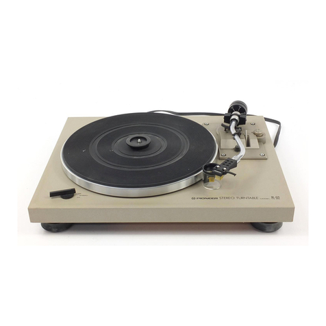
Pioneer PL-6 User manual

Enqlish/German/French/talian
Instructions
;
aa
fy
WE
“aaa,
This
operation
manual
is
written
in
four
languages.
The
English
is
from
page
1
to
page
12,
the
Ger-
man
from
page
13
to
page
22,
the
French
from
page
23
to
page
32
and
the
Italian
from
page
33
to
page
42.
Please
read
the
pages
in
your
language
to
learn
to
use
this
product
correctly.
Diese
Bedienungsanleitung
ist
in
vier
Sprachen
abgefaf&t.
Der
englische
Text
reicht
von
Seite
1
bis
Seite
12,
der
deutsche
Text
von
Seite
13
bis
Seite
22,
der
franzésische
Text
von
Seite
23
bis
Seite
32
und
der
italienische
Text
von
Seite
33
bis
Seite
42.
Lesen
Sie
bitte
die
Seiten
in
Ihrer
Muttersprache
aufmerksam
durch,
um
sich
mit
diesem
Produkt
gut
vertraut
zu
machen.
Ce
manuel
d’utilisation
a
été
rédigé
en
quatre
langues.
La
version
anglaise
va
de
la
page
1
a
la
page
12,
ia
version
allemande
de
la
page
13
a
la
page
22,
la
version
frangaise
de
la
page
23
4
la
page
32
et
la
version
italienne
de
la
page
33
a
la
page
42.
Veuillez
lire
les
instructions
dans
la
langue
qui
vous
intéresse
pour
apprendre
4
utiliser
correctement
ce
produit.
Questo
manuale
d’istruzioni
per
I’uso
é
redatto
in
quattro
lingue.
L’inglese
é
da
pag.
1
a
pag.
12,
il
tedesco
da
pag.
13
a
pag.
22,
il
francese
da
pag.
23
a
pag.
33
e
I’italiano
da
pag.
33
e
pag.
42.
Leg-
gere
attentamente
le
istruzioni
nella
propria
lingua
per
usare
correttamente
questo
prodotto.
@Q)
PIONEER’

CONTENTS
Panel
Facilities
..
0.0...
0...
c
cece
eee
ee
eee
B
Maintenance
...
21...
0...
ccc
eee
eee
Operations
before
Use
.............
2,
desea
des
Bis-ete
Troubleshooting
............
000
c
cee
ee
ee
eee
Record:
Play
2.f
05.0
bios
hee
hte
ietiri
tes
hee
Specifications
©...
0...
cece
ee
ees
IMPORTANT
To
prevent
electric
shock,
do
not
remove
cover.
No
user
serviceable
parts
inside,
refer
servicing
to
qualified
service
personnel.
Always
disconnect
all
the
equipment
from
the
mains
supply
when
disconnecting
the
signal
leads.
The
power
cord
should
be
connected
last,
make
sure
that
the
power
switch
is
off.
Unplug
the
set
from
the
wall
socket
when
it is
not
to
be
used
for
an
extended
period
of
time.

PANEL
FACILITIES
@
CUT
switch
Depress
this
switch
to
stop
play.
(For
details,
refer
to
page
8.)
(2)
Quartz
lock
indicator
This
tights
when
the
platter
is
rotating
at
exactly
33-1/3
or
45
revolutions
per
minute.
(3)
SPEED
switch
Set
this
switch
in
accordance
with
the
speed
of
the
re-
cord
which
is
to
be
played.
[33]
(depressed
position):
For
33-1/3
rpm
records
[45]
(released
position):
For
45
rpm
records
(@)
Cartridge
(PC-3MC)
(5)
Headshell
(6)
Tonearm
@
ARM
ELEVATION
lever
Operate
this
lever
when
starting
record
play
or
when
temporarily
suspending
play.
(For
details,
refer
to
page
7
or
8.)
©o
Q
©
ANTI-SKATE
control
This
is
rotated
when
performing
the
anti-skating
adjust-
ment.
(For
details,
refer
to
page
5.)
@)Arm
rest
This
serves
to
hold
and
clamp
the
tonearm.
When
moving
the
tonearm,
release
the
clamp.
(For
details,
refer
to
page
5.)
Tracking
force
adjustment
weight
This
is
used
when
adjusting
the
tracking
force.
(For
details,
refer
to
page
5.)
()
Platter
(2
Platter
mounting
shaft
(3)
Rubber
mat
EP
adapter
This
is
used
when
playing
records
without
a
“‘middle.”’
(5)
Cabinet
Dust
cover

OPERATIONS
BEFORE
USE
STEP
1}
Assembling
the
Turntable
Removing
the
dust
cover
1.
Open
the
dust
cover
as
far
as
it
will
go.
2.
Hoid
both
sides
of
the
dust
cover
and
remove
it
from
the
cabinet
by
pulling
it
up.
NOTE:
Take
care
not
to
mark
or
scratch
the
dust
cover
which
you
have
now
removed.
Checking
the
accessories
The
accessories
are
housed
in
the
polystyrene
cushions
which
are
used
to
package
the
turntable
proper.
EP
adapter
Tracking
force
ad-
This
is
used
to
play
justment
weight
records
without
a
This
is
mounted
on-
“middle.”
to
the
end
of
the
tonearm.
Removing
the
transit
screws
Using
a
Phillips
head
screwdriver,
rotate
the
transit
screws
(3)
in
the
direction
of
the
arrow
in
the
figure
and
remove
the
platter
and
the
platter
cushions.
Phillips
head
screwdriver
NOTE:
@The
turntable
will
not
operate
unless
these
screws
are
removed.
®Keep
the
screws
and
cushions
in
a
safe
place
since
they
are
required
when
transporting
the
turntable
from
place
to
place.
Mouting
the
platter
and
rubber
mat
1.
Place
the
platter
over
the
platter
mounting
shaft.
2.
Place
the
rubber
mat
on
top
of
the
platter.
shaft
Cr
NOTE:
When
mounting
the
platter,
take
care
not
to
bump
it
into
the
platter
mounting
shaft,
the
cabinet
and
the
tonearm.
Bh
(Before
using
your
turntable,
carry
out
the
instructions
in
step
1
through
step
4.)
weight
Insert
the
weight
over
the
end
of
the
weight
shaft
with
the
scale
side
turned
in
front.
2.
Push
it
a
short
way
along
the
shaft
and
rotate
the
weight
part
(indicated
as
in
figure)
in
the
direction
indicated
by
the
arrow
for
two
or
three
turns.
Attaching
the
tracking
force
adjustment
1.
Z7>\__—
Tracking
force
adjustment
A
B®)
[6]
Mounting
the
dust
cover
1.
Hold
both
sides
of
the
dust
cover
and
slide
the
hinges
into
the
cabinet’s
hinge
holders.
2.
Push
down
until
the
dust
cover
goes
no
further.
Dust
cover
/
Hinge]
A
2
Hinge
holder
—-23_———CS7
J]
SS
eee

STEP
2}
Adjusting
the
Tracking
Force
and
Anti-Skating
[1]
Setting
the
ANTI-SKATE
control
to
[0]
Rotate
the
control
in
the
direction
indicated
ey
the
arrow
and
align
[0]
with
‘the
index
line.
Index
line
DOWN
Pull
down
the
lever
toward
you.
Removing
the
stylus
cover
[4]
Releasing
the
arm
rest.
Move
the
arm
rest
in
the
direction
of
the
arrow
by
hand.
NOTE:
Hold
the
tonearm
with
your
other
hand
since
it
may
move.
Moving
the
tonearm
Move
the
tonearm
to
between
the
arm
rest
and
platter.
[6]
Attaining
the
horizontal
balance
(make
the
tonearm
parallel)
As
sh
in
the
figure,
rotate
the
weight
part
(indicated
as
&
==
in
figure)
of
the
tracking
force
adjustment
weight
in
the
direction
indicated
by
the
arrow
and
adjust
it
so
that
the
tonearm
remains
parallel
to
the
cabinet
when
it
is
released.
Anchoring
the
tonearm
to
the
arm
rest
Setting
the
tracking
force
scale
ring
to
[0]
Rotate
only
the
tracking
force
scale
ring
(indicated
as
in
figure)
of
the
tracking
force
adjustment
weight
in
either
of
the
directions
shown
by
the
arrows
and
align
[0]
with
the
index
line.
Tracking
force
scale
ring
OPERATIONS
BEFORE
USE
NOTE:
®@Hold
the
weight
part
with
your
other
hand
to
prevent
it
from
rotating
with
the
ring.
@Once
the
weight
part
has
been
rotated,
attain
the
horizontal
balance
again
as
under
section
[6]
[9]
Adjusting
the
tracking
force
Rotate
the
weight
(indicated
as
in
the
the
arrow
(the
tracking
force
scale
ring
also
rotates
to-
gether)
and
align
the
2.0
position
on
the
scale
ring
with
the
index
line.
@One
scale
unit
on
the
tracking
force
scale
ring
is
0.19.
@A
tracking
force
of
3g
is
applied
with
every
turn
of
the
weight.
Adjusting
the
anti-skating
ig
e
Rotate
the
anti-skating
con-
S
trol
in
the
direction
of
the
arrow
and
align
the
2.0
point
on
the
control
with
the
index
line.

OPERATIONS
BEFORE
USE
STEP
3}
Connecting
the
Turntable
and
Amplifier
Connecting
the
ground
wire
Attach
the
metal
fitting
onto
the
amplifier
ground
(GND)
terminal.
Connecting
the
output
cords
Insert
the
pltigs
into
the
ampli-
Connecting
the
power
cord
Connect
the
power
plug
to
the
auxiliary
“AC
OUTLET”
on
the
amplifier
or
to
a
household
power
fiers
input
“PHONO”
terminals.
®@Connect
the
white
plug
to
the
left
(L)
channel
and
the
red
plug
to
the
right
(R)
channel.
@lnsert
the
plugs
as
far
as
they
will
go.
|
outlet.
_
STEP
4/
Installing
the
Turntable
Take
note
of
the
following
points
and
install
the
turntable
properly.
Find
a
location
which:
@!s
horizontal
and
flat.
@/s
characterized
by
minimal
floor
vibration
or
is
not
affected
by
any
vibrations
transmitted.
@ls
not
affected
by
high
sound
pressures
or
vibrations
from
the
speaker
system.
:
(Do
not
install
the
turntable
immediately
in
front
of,
or
on
top
of,
the
speakers.)
@Allows
easy
operation
and
gives
visible
access
to
the
record
and
styius.
After
having
carried
out
steps
[1]
through
[4],
read
through
the
following
checkpoints.
Check
the
tracking
force
and
anti-skating
adjustments.
|
@The
ANTI-SKATE
control
must
be
aligned
with
the
same
number
as
the
tracking
force.
The
following
troublé
is
apparent
when
the
number
does
not
tally
with
the
tracking
force:
Too
high:
The
sound
is
distorted
and
the
tonearm
slides
toward
the
outside
of
the
record.
Too
low:
The
tonearm
slides
toward
the
inside
of
the
re-
cord
when
the
stylus
descends
onto
the
record.
©The
tracking
force
must
be
adjusted
within
the
correct
tracking
force
range
of
the
cartridge.
The
following
trouble
is
apparent
when
the
tracking
force
is
not
properly
adjusted:
Excessive
tracking
force:
The
sound
is
distorted
and
the
cartridge
itself
touches
the
record.
Insufficient
tracking
force:
The
sound
is
distorted
and
interrupted.
®The
tracking
force
must
be
adjusted
with
the
ANTI-
SKATE
control
at
[0].
Unless
this
control
is
set
to
the
[0]
position,
a
force
is
generated
by
the
anti-skating
mechanism
which
pulls
the
tonearm
to
the
right
(toward
the
arm
rest).
Therefore,
when
attaining
the
horizontal
balance,
the
tonearm
is
not
at
rest
and
so
the
operation
is
difficult
to
perform.
Even
at
the
[0]
position
there
may
be
some
movement.
This
is
due
to
the
increased
rotational
sensitivity
of
the
tonearm
enabling
the
stylus
to
trace
efficiently
the
sound
grooves
on
the
record,
and
it
does
not
indicate
that
there
is
anything
wrong
with
the
turntable.
S
@\s
near
to
the
stereo
amplifier.
(Inscall
the
turntable
within
a
range
where
the
con-
necting
cords
reach
the
terminals
on
the
amplifier.)
@is
not
directly
exposed
to
direct
sunlight
or
heat
from
heating
appliances.
(Do
not
install
the
turntable
near
a
heater
or
on
a
window
ledge
exposed
to
the
sun.)
@\s
not
exposed
to
dust
and
dirt.
@ls
free
from
damp
and
moist
air.
Check
the
installation
and
connections
of
the
turntable
©
Connection
must
be
made
to
the
amplifier’s
PHONO
MM
terminals.
@
When
using
a
cartridge
other
than
that
supplied.
Consult
the
Operating
Instructions
of
the
cartridge
and
stereo
amplifier
and
proceed.
@Incorrect
connections
of
installation
will
lead
to
trouble
If
the
equipment
is
connected
improperly,
no
sound
will
be
heard.
If
the
output
cord
plugs
are
not
inserted
as
far
as
they
will
go
or
if
the
ground
wire
is
not
connected,
humm-
ing
noise
will
be
heard
through
the
speakers.
If
the
turntable
is
installed
at
an
angle,
the
tonearm
will
slide
on
the
record
and
the
sound
will
be
distorted.
If
vibrations
are
transmitted
to
the
turntable,
the
sound
may
be
discontinuous
or
it
may
tremble,
and
in
some
cases
howl
(a
prolonged
wailing
sound
from
the
speakers)
may
be
heard.
®@The
connecting
cords
should
be
given
some
slack
Check
that
none
of
the
connecting
cords
are
pulled
taut
after
they
have
been
connected.
Tautness
may
lead
to
cord
disconnections
and
howl.

RECORD
PLAY
When
Using
the
Turntable
for
the
First
Time
The
turntable
may
operate
unstably
due
to
the
vibrations
sustained
during
transportation.
Proceed
as
follows
to
restore
the
turntable
to
its
normal
working
operation.
This
procedure
is
observed
only
once;
on
other
occasions
it
may
be
disregarded.
Set
the
ARM
ELEVATION
lever
to
the
UP
position.
Release
the
arm
rest.
Move
the
tonearm
by
hand.
@The
platter
starts
to
rotate.
®
Release
the
tonearm
after
having
moved
it.
Depress
the
CUT
switch
Several
seconds
after
the
switch
has
been
depressed,
the
tonearm
returns
automatically
to
the
arm
rest
and
the
platter
stops
rotating.
[Q]
Adiust
the
volume
and
tone
using
the
controls
on
the
stereo
amplifier.
(When
play
is
completed,
the
tonearm
returns
auto-
matically
to
the
arm
rest.)
:
Set
the
stereo
amplifier
up
for
record
play.
Set
the
amplifier’s
power
switch
to
ON
and
set
the
function
selector
to
the
PHONO
position.
Place
the
record
onto
the
platter.
Remove
the
stylus
cover
Release
the
armrest
Depress
the
SPEED
switch
and
set
the
speed:
Depressed
position
for
playing
33-1/3
rpm
records
Released
position
for
playing
45
rpm
records
Set
the
ARM
ELEVATION
lever
to
the
UP
position
Move
the
tonearm
by
hand
across
to
the
record.
Release
the
headshell
when
the
stylus
has
been
posi-
tioned
on
the
record
at
the
right
track.
@
The
platter
starts
to
rotate.
@
The
stylus
is
still
floating
clear
of
the
record
and
so
no
sound
will
be
heard
yet.
S|
Set
the
ARM
ELEVATION
lever
to
the
DOWN
position
and
start
play.
The
stylus
descends
onto
the
record
and
play
begins.

RECORD
PLAY
Temporarily
Suspending
Play
This
can
be
done
in
two
ways
e
Depress
the
CUT
switch
Several
seconds
after
this
switch
is
set,
the
tonearm
automatically
returns
to
the
arm
rest
and
the
platter
stops
rotating.
Record
play
precautions
eWhen
the
tonearm
does
not
return
automatically
If
a
record
with
a
non-standard
size
is
being
played,
the
tonearm
may
not
return
even
after
play
or
it
may-return
before
the
completion
of
play.
In
cases
like
this,
depress
the
CUT
switch
and
the
record
play
is
concluded
auto-
matically.
e
Clean
the
stylus
and
records
before
and
after
play
(refer
to
page
9
)
Dust
or
dirt
on
the
stylus
or
records
will
result
in
dis-
torted
and
discontinuous
sound.
Remove
the
dust
on
the
stylus
with
a
soft
brush.
Use
a
good-quality
record
cleaner
obtainable
from
your
dealer
to
remove
dust
and
dirt
on
your
records.
e
Set
the
ARM
ELEVATION
lever
to
the
UP
position
The
stylus
rises
from
the
surface
of
the
record
and
play
stops
(but
the
platter
continues
rotating).
When
the
tonearm
is
returned
manually
to
the
arm
rest,
the
platter
stops
rotating.
NOTE:
After
the
tonearm
has
been
returned
manually
to
the
arm
—
rest,
always
remember
to
set
the
ARM
ELEVATION
lever
to
the
DOWN
position.
e
Place
only
one
record
on
the
platter
at
a
time
If
two
or
more
records
are
placed,
the
angle
of
the
stylus
on
the
record
will
deviate,
resulting
in
distorted
sound.

MAINTENANCE
|
Replacing
the
Stylus
|
©
The
service
life
of
the
stylus
on
the
cartridge
supplied
ranges
from
800
to
1,000
hours
(If
the
stylus
is
used
for
1
or
2
hours
every
day,
it
will
last
for
one
or
two
years.)
_
Using
a
worn
or
damaged
stylus
can
damage
the
record
and
distort
the
sound
reproduced.
Remember
to
replace
the
stylus
at
the
earliest
possible
date.
e
Obtain
the
PN-3MC
replacement
stylus
from
the
PIONEER
dealer
from
whom
you
pur-
chased
the
unit
The
cartridge
mounted
on
this
unit
was
developed
by
PIONEER.
Oniy
a
specially
designed
replacement
stylus
may
be
used
and
this
may
be
obtained
from
your
PIONEER
dealer.
e
Always
use
a
PIONEER
replacement
stylus
and
no
other
Using
a
replacement
stylus
made
by
another
company
will
make
it
impossible
for
PIONEER
to
guarantee
that
there
will
be
no
resulting
deterioration
in
quality
or
malfunctions.
PIONEER’S
company
logo
is
stamped
on
all
the
company’s
genuine
replacement
styli.
Replacing
the
stylus
procedure
1.
Anchor
the
tonearm
to
the
arm
rest
2.
Remove
the
headshell
from
the
tonearm
Use
a
small
screwdriver
to
rotate
the
anchoring
screw
in
the
direction indicated
by
the
arrow
to
remove
the
headshell.
When
removing
the
head-
shell,
hold
this
part
with
your
hand.
3.
Disconnect
the
leads
from
the
cartridge
Use
a
small
screwdriver
or
tweezers
to
disconnect
the
leads.
4.
Remove
the
stylus
from
the
cartridge
Insert
a
small
screwdriver
into
cartridge’s
slot
and
rotate
as
shown
in
the
figure.
(The
stylus
holder
will
rise
slightly.)
Hold
the
stylus
holder
and
pull
the
stylus
gently
in
the
direction
indicated
by
the
arrow.
Stylus
holder
t
5.
Connect
the
leads
to
the
new
stylus
holder
White
lead
is
connected
LG:
Blue
lead
is
connected
RG:
Green.lead
is
connected
R:
Red
lead
is
connected
Turn
the
aligning
surface
of
the
terminals
up
and
insert.
NOTE:
Take
care
not
to
touch
the
stylus
of
the
new
stylus
holder,
the
internal
coil
and
the
leads.
In
particular,
take
care
not
to
touch
this
part.
6.
Attach
the
new
stylus
holder
to
the
cartridge
Align
the
holder
with
the
guides
and
press
onto
the
car-
tridge
until
it
clicks
into
place.
Guide
Guide
7.
Mount
the
headshell
onto
the
tonearm
Follow
the
procedure
of
section
2
in
reverse.
Push
the
headshell
as
far
as
it
will
go
and
then
secure
it.
Maintaining
the
turntable
e@
When
the
cabinet
is
dirty
or
dusty
Use
a
polishing
cloth
or
a
dry
soft
cloth
to
clean
off
the
dirt
and
dust.
e@
When
the
cabinet
is
stained
Dip
a
soft
cloth
into
neutral
detergent
diluted
with
five
or
six
times
the
amount
of
water,
wring
the
cloth
out
and
clean
off
the
stains.
Next,
wipe
off
all
the
remaining
moisture
with
a
dry
soft
cloth.
@
Do
not
use
chemicals
or
furniture
wax
Never
use
furniture
wax,
cleaners,
thinners
or
benzene
for
cleaning
since
these
will
mar
and
discolor
the
surface
finish
of
the
cabinet.
e
Do
not
spray
with
insecticides
If
insecticide
sprays
are
allowed
to
come
into
contact
with
the
surface
of
the
cabinet,
the
surface
may
be
dis-
colored
and
the
finish
spoiled.
[Maintaining
the
stylus|
e
Use
a
soft
brush
\
rs
-
As
shown
in
the
figure,
move
the
brush
toward
you
to
clear
K
use
your
finger
since
this
will
damage
the
stylus.
e@
When
the
dirt
cannot
be
removed
by
a
brush
Obtain
some
stylus
cleaner
from
your
dealer
and
remove.
Do
not
allow
any
of
the
liquid
to
come
into
contact
with
the
plastic
parts
as
they
may
dissolve.
off
the
dust
and
dirt.
Do
not
9
RNY

TROUBLESHOOTING
Incorrect
operations
are
often
mistaken
for
trouble
and
malfunctions.
If
you
think
that
there
is
something
wrong
with
your
turntable,
check
out
the
points
below.
Sometimes,
the
trouble
may
lie
in
another
component.
Investigate
the
stereo
amplifier,
speaker
systems
and
other
electrical
apparatus
which
are
being
used.
If
the
trouble
cannot
be
rectified
even
after
exercising
the
checks
listed
below,
ask
your
nearest
PIONEER
authorized
service
center
or
your
dealer
to
carry
out
repair
work.
Symptom
Cause
Remedy
Ref.
page
Platter
does
not
rotate
@
Disconnected
power
plug
@Connect
the
power
plug
securely
to
the
6
AC
outlet.
;
@When
turntable
is
connected
to
AC
|
@
Set
the
amplifier’s
power
switch
to
ON.
6
OUTLET
(SWITCHED)
on
stereo
amplifier
No
sound
e@
Faulty
output
cord
connections
@insert
pin
plugs
firmly
into
amplifier’s
6
PHONO
terminals.
e@
Faulty
cartridge
lead
connections
(when
|
@
Connect
properly.
11
the
cartridge
has
been
replaced)
Sound
is
discontinuous
or
distorted;
noise
from
scratches
is
heard
Hum
(heard
through
speakers)
@
Incorrect
tracking
force
e
Apply
tracking
force
commensurate
with
cartridge.
e@
Excessive
anti-skating
@
Apply
value
commensurate
with
cartridge.
e
Dirty
stylus
e@
Clean
stylus.
@
Worn
stylus
@
Replace
with
new
stylus.
@
Dirt
or
dust
on
record
@
Record
warp
or
scratches
@
Dirty
pin
plugs
or
amplifier
input
termi-
nals.
@
Clean
record.
e@
Replace
record.
@
Clean
off
dirt.
Howl
(if
the
volume
is
turned
up
during
record
play,
acoustic
feedback
fills
the
whole
room)
Odd
sound
tempo
e@
SPEED
switch
is
not
at
correct
position.
speed.
@
Cartridge
mounting
is
bent
(when
cart-
|
@
Correct
bending.
11
ridge
has
been
replaced).
eFaulty
output
cord
or
ground
wire
con-
|
@Connect
properly
to
amplifier’s
PHONO
6
nection.
or
GND
terminal.
@Dirty
pin
plugs
or
amplifier
input
ter-
|
@
Clean
off
dirt.
-
minals.
e@
Adverse
effect
of
flux
from
amplifier’s
|
@
Vary
positions
of
amplifier
and
turntable.
_
power
transformer.
e@
Vibrations
from
speakers
are
being
trans-
|
@
Place
turntable
at
a
distance
from
speakers
-
mitted
to
the
floor
and
these
are
being
so
that
vibrations
are
not
transmitted
picked
up
by
cartridge.
from
floor.
e
Place
turntable
on
sturdy
stand.
-
e@Sound
pressure
from
speakers
is
trans-
|
@
Try
varying
installation
location
of
turn-
_
mitted
directly
to
cartridge.
table.
|
@Set
to
position
that
agrees
with
record
10

SPECIFICATIONS
Motor
and
Turntable
Drive
System
...................04.
Direct-drive
Motor.
3
acne
aed
OU
Quartz
PLL
Hall
motor
Turntable
Platter
...........
310mm
diam,
aluminum
alloy
die-cast
Speeds
5.
x
oe)
sea
eise
ened
e
aokewes
ee
whoa
33-1/3
and
45rpm
Wow
and
Flutter
.........
Less
than
0.025%
(WRMS)
Signal-to-Noise
Ratio........
More
than
78dB
(DIN-B)
(with
Pioneer
catridge
model
PC-3MC)
Tonearm
TYRE:
ees
ea
eos
Static-balance
type,
Straight
pipe
arm
Effective
Arm
Length
................00.
221mm
Overhang:
2.02.03
348
35
eae ewe
tot
aes
15.5mm
Usable
Cartridge
Weight
........
3g
(min.)
to
8g
(max.)
Subfunctions
Auto-return
mechanism,
Anti-skating
force
control,
Stylus
pressure
direct-readout
counterweight,
Cueing
device,
Strobe
light,
Free
stop
hinges
Condensation
When
this
turntable
is
brought
into
a
warm
room
from
previously
cold
surroundings
or
when
the
room
tem-
perature
rises
sharply,
condensation
may
form
inside
and
the
unit
may
not
do
full
justice
to
its
performance.
In
cases
like
this,
allow
the
unit
to
stand
for
about
an
hour
or
raise
the
room
temperature
gradually.
Miscellaneous
Power
Requirements
......
AC220
—
240V
~,
50,
60
Hz
Power
Consumption
.................0
004
12W
Dimensions
..........
420(W)
x
108(H)
x
367(D)mm
16-1/2(W)
x
4-1/4(H)
x
14-7/16(D)
in.
Wight:
x2
oc
Soe
88s.
ok
a
Soe
ote
ets
5.8kg/12
Ib
13
oz.
PC-3MC
Specifications
PY
D@e,
eve
toe
eh
Se
Sepa
ats,
Se
ee
AG
eased
Moving
coil
type
Stylusiit
as
208
3
oe
eS
ies
0.5
mil
diamond
(PN-3MC)
Output
Voltage
...
2.0...
0.0.0.0...
eee
2.5mV
(1kHz,
50mm/s
Peak
velocity,
LAT)
Tracking
Force.............
1.7g
to
2.3g
(proper
2g)
Frequency
Response
...............
10
to
32.000Hz
Recommended
Load
.................200.
50kQ
WeIGKE
ones
sie
eat
eae?
aise
Sa
eds
Sadie
AS
a
wd
3.1g
Accessories
EP:
Adapter’.
25.
.0!e
0
hua
dd
ceded
Sosa
Ged
BES
1
Operating
Instructions...
2.2.0.0...
...
0.000
eee
1
NOTE:
Specifications
and
design
subject
to
possible
modification
without
notice,
due
to
impromements.
Cartridge
replacement
@
Any
cartridge
besides
that
supplied
having
a
weight
of
between
3
and
8
g
may
be
used
with
this
turntable.
@
The
polarities
of
the
accessory
headshell’s
leads
are
as
shown
below.
Align
them
properly.
Red:
Right
channel
(R)
Green:
Right
channel
ground
(RG)
White:
Left
channel
(L)
Blue:
Left
channel
ground
(LG)
@
The
overhang
of
the
tonearm
is
15.5
mm.
When
using
the
accessory
headshell,
the
overhang
can
be
adjusted
when
the
stylus
and
connector
dimensions
are
set
to
56
mm.
(Unacceptable
mounting)
Cartridge
is
bent
(Acceptable
mounting)
Must
be
mounted
in
parallel
After
having
replaced
the
cartridge,
refer
to
page
5
and
perferm
the
tracking
force
and
antiskating
adjustments
again.
11


STEREO-PLATTENSPIELER
L-6
Bedienungsanleitung
INHALT
Einrichtungen
an
der
Oberseite
..............
14
Wartuing:
acoso
4004
eels
ES
Seed
Sas
oes
Vorbereitungen
vor
der
Inbetriebnahme
........
15
Fehlersuchtabelle
............0
0002
ee
eee
Abspielen
von
Schallplatten
................
18
WICHTIG
Um
elektrischen
Schlag
zu
vermeiden,
die
Abdeckung
nicht
entfernen.
Im
Inneren
befinden
sich
keine
Teile,
die
vom
Benutzer
gewartet
werden
kénnen;
Wartungsarbeiten
diirfen
nur
von
einem
qualifizier-
ten
Kundendiensttechniker
ausgefulhrt
werden.
Beim
Trennen
der
Signalkabel
stets
die
ganze
Anlage
vom
Netz
trennen.
Das
Netzkabel
sollte
zuletzt
getrennt
werden;
sicherstellen,
dal§
der
Netzschalter
ausgeschaltet
ist.
Bei
langerer
Nichtverwendung
des
Gerates
des
Netzkabelstecker
aus
der
Netzsteckdose
ziehen.
VY)
PIONEER’

EINRICHTUNGEN
AN
DER
OBERSEITE
@)
Ausschalter
(CUT)
Diesen
Schalter
niederdriicken,
um
das
Abspielen
zu
beenden.
(Einzelheiten
sind
auf
Seite
19
angegeben.)
@
Quarzsynchronisierungsanzeige
Diese
Anzeige
leuchtet
auf,
wenn
sich
der
Plattenteller
mit
genau
33-1/3
oder
45
Umdrehungen
pro
Minute
dreht.
Drehzahlschalter
(SPEED)
Diesen
Schalter
gema
der
Drehzahl
der
zum
Abspielen
vorge-
sehenen
Schaliplatte
einstellen.
(33]
(niedergedriickte
Stellung):
Fir
33-1/3U/min-Schallplatten
[45]
(ausgerastete
Stellung):
Fir
45U/min-Schallplatten
@
Tonabnehmersystem
(PC-3MC)
©)
Kopfmuschel
(6)
Tonarm
(7)
Tonarmlifthebel
(ARM
ELEVATION)
14
Diesen
Hebel
vor
dem
Abspielen
einer
Schallplatte
oder
zum
voriibergehenden
Unterbrechen
des
Abspielens
betatigen.
(Ein-
zelheiten
sind
auf
Seite
18
oder
19
angegeben.)
@
©
@@Oe@
®
Oo
eg
©
Antiskatingregler
(ANTI-SKATE)
Diesen
Regler
zum
Einstellen
der
Antiskatingkraft
drehen.
(Ein-
zelheiten
sind
auf
Seite
16
angegeben.)
Tonarmauflage
Diese
Auflage
dient
zum
Stiitzen
und
Festklemmen
des
Tonarms.
Zum
Bewegen
des
Tonarms
die
Klemme
Idsen.
(Einzelheiten
sind
auf
Seite
16
angegeben.)
Auflagekrafteinstellgewicht
Dieses
Gewicht
dient
zum
Einstellen
der
Auflagekraft.
(Einzel-
heiten
sind
auf
Seite
16
angegeben.)
Plattenteller
Plattentellerbefestigungsachse
Gummimatte
Mittelstiick
fiir
45U/min-Schallplatten
Dieses
Mittelstiick
wird
beim
Abspielen
von
Schallplatten
ohne
‘Mitte’
verwendet.
Gehause
Abdeckhaube
:
|
if
:
;
i
i
i
i
i
i
|
i
}
i
|
i
i
|
i
|
I
|
i
{
{
{
|

vo
R
B
E
R
E
IT
U
N
G
E
N
vo
R
(Vor
Inbetriebnahme
dieses
Plattenspielers
DER
INBETRIEBNAHME
gema&
den
Schritten
1
bis
4
vorgehen.)
SCHRITT
1;
Zusammenbauen
des
Plattenspielers
Entfernen
der
Abdeckhaube
1.
Die
Abdeckhaube
bis
zum
Anschlag
offnen.
2.
Die
Abdeckhaube
auf
beiden
Seiten
festhalten
und
durch
Hochziehen
vom
Gehause
entfernen.
Anmerkung:
Darauf
achten,
daB
die
entfernte
Abdeckhaube
nicht
angeritzt
oder
verkratzt
wird.
Uberpriifen
der
ZubehGrteile
Die
ZubehGrteile
sind
in
den
Polystyrolpolstern
untergebracht,
die
zum
Verpacken
des
Plattenspielers
verwendet
werden.
Mittelstiick
fiir
45U/
min-Schallptatten
Dieses
Mittelstiick
wird
beim
Abspielen
Auflagekraftein-
stallgewicht
Dieses
Gewicht
wird
am
Tonarmende
an-
von
Schallplatten
gebracht.
ohne
“Mitte”
ver-
wendet.
Entfernen
der
Transportschrauben
Die
Transportschrauben
(3)
mit
Hilfe
eines
Kreuzschlitz-
schraubenziehers
gema&
Abbildung
in
Pfeilrichtung
drehen,
dann
den
Plattenteller
und
die
Plattentellerpolster
entfernen.
we
PF
Kreuzschlitzschraubenzieher
71S
f=
Ss
_—
Transportschraube
Plattenteller
Ke
ED
Le
4
Plattentellerpoister
Anmerkung:
e@
Der
Plattensieler
functioniert
nur
dann,
wenn
diese
Schrauben
entfernt
werden.
e
Die
Schrauben
und
Polster
an
einem
sicheren
Platz
auf-
bewahren,
da
sie
beim
Transportieren
des
Plattenspielers
von
Platz
zu
Platz
bendtigt
werden.
Anbringen
des
Plattentellers
und
der
Gummimatte
1.
Den
Plattenteller
auf
die
Plattentellerbefestigungsachse
setzen.
2.
Die
Gummimatte
auf
den
Plattenteller
legen.
Plattenteller
Plattenteller-
befestigungs-
achse
Anmerkung:
Beim
Anbringen
des
Plattentellers
darauf
achten,
diesen
nicht
gegen
die
Plattentellerbefestigungaschse,
das
Gehause
oder
den
Tonarm
zu
stoBen.
Anbringen
des
Auflagekrafteinstellgewichts
1.
Das
Gewicht
so
auf
das
hintere
Teil
des
Tonarms
schieben,
da
die
Skalenseite
nach
vorn
weist.
2.
Das
Gewicht
etwas
am
Roh
entlang
schiben
und
den
(in
der
Abbildung
durch
gekennzeichneten)
Ge-
wichtsteil
um
zwei
oder
drei
Umdrehungen
in
Pfeilrichtung
drehen.
Caen
Auflagekrafteinstellgewicht
[6]
Befestigen
der
Abdeckhaube
1.
Die
Abdeckhaube
auf
beiden
Seiten
festhalten
und
die
Schar-
niere
in
die
Scharnierhalterungen
des
Gehauses
schieben.
2.
Die
Abdeckhaube
bis
zum
Anschlag
nach
unten
driicken.
Abdeckhaube
Scharnier
—__F
4
Scharnierhalterung
—
EX)
15

VORBEREITUNGEN
VOR
DER
INBETRIEBNAHME
SCHRITT
2|
Eiinstellen
der
Auflage-
und
Antiskatingkraft
r
Einstellen
des
Antiskatingreglers
(ANTI-SKATE)
auf
“QO”
Den
Regler
in
Pfeilrichtung
drehen
und
“O”
auf
den
Indexstrich
ausrichten.
—
,
Indexstrich
Einstellen
des
Tonarmlifthebels
(ARM
ELEVATION)
auf
‘‘Absenken”
ie
“Ren
Poy,
Den
Hebel
nach
vorn
herunterziehen.
Entfernen
des
Nadelschutzes
Lésen
der
Tonarmauflage
Die
Tonarmauflage
mit
der
Hand
in
Pfeilrichtung
bewegen.
r
Anmerkung:
Den
Tonarm
mit
der
anderen
Hand
festhalten,
weil
er
sich
bewegen
kann.
Bewegen
des
Tonarms
Den
Tonarm
die
Tonarmaufiage
und
den
Plattenteller
bewegen.
Einstellen
der
horizontalen
Balance
(Tonarm
ist
parallel
zur
Gehauseoberseite)
Den
(in
der
Abbildung
durch:
Gewichtsteil
des
Auflagekrafteinstellgewichts
gema&
Abbil-
dung
in
Pfeilrichtung
drehen
und
so
einstellen,
da&
der
Tonarm
beim
Loslassen
parallel
zur
Gehauseoberseite
bleibt.
Festklemmen
des
Tonarms
in
der
Tonarmauflage
Einstellen
des
Auflagekraftskalenrings
auf
““O”
Nur
den
(in
der
Abbildung
durch
=
gekennzeichneten)
Auflagekraftskalenring
des
Auflagek
eligewichts
in
Pfeil-
richtung
nach
links
oder
rechts
drehen
und
‘‘O”
auf
den
Index-
strich
ausrichten.
Indexstrich
Auflagekraftskalenring
16
Anmerkung:
@
Den
Gewichtsteil
mit
der
anderen
Hand
festhalten,
damit
sich
dieser
nicht
zusammen
mit
dem
Ring
dreht.
e@
Nach
Drehen
des
Gewichtsteils
nochmals
die
horizontale
Balance
gema&
Abschnitt
[6]
einstellen.
(9)
Einstellen
der
Auflagekraft
Den
(in
der
Abbildung
durch
gekennzeichneten)
Ge-
wichtsteil
in
Pfeiirichtung
drehen
(der
Auflagekraftskalenring
dreht
sich
mit)
und
2.0"
am
Skalen-
ring
auf
den
Indexstrich
aus-
richten.
@
Eine
Skaleneinheit
des
Auf-
lagekraftskalenrings
entspricht
0,1
g.
@
Mit
jeder
Umdrehung
des
Gewichts
wird
eine
Auflagekraft
von
3
g
ausgeiibt.
Einstellen
des
Antiskatingreglers
Den
Antiskatingregler
in
Pfeil-
richtung
drehen
und
‘2.0
am
Regler
auf
den
Indexstrich
aus-
richten.
Gewichtsteil

VORBEREITUNGEN
VOR
DER
!INBETRIEBNAHME
SCHRITT
3|
Anschlie&en
des
Plattenspielers
und
Verstarkers
1
AnschlieBen
der
Erdleitung
Das
Metalistick
an
der
Erd-
klemme
(GND)
des
Verstarkers
anbringen.
AnschlieBen
der
ce
Die
Stecker
in
die
Plattenspieler-
Eingangsbuchsen
(PHONO)
des
Verstarkers
stecken.
AnschlieBen
des
Netzkabels
Den
Netzkabelstecker
in
den
Reservenetzausgang
(AC
OUT-
LET)
des
Verstarkers
oder
in
eine
@eDen
weien
Stecker
in
die
Buchse
fiir
den
linken
(L)
Kanal
und
den
roten
Stecker
in
die
Buchse
fiir
den
rechten
(R)
Kanal
stecken.
@Die
Stecker
bis
zum
Anschlag
hineinstecken.
Netzsteckdose
stecken.
SCHRITT
4}
Aufstellen
des
Plattenspielers
@
waagerecht
und
eben
ist;
@
der
mdglichst
wenig
Bodenerschiitterung
ausgesetzt
ist
und
auf
den
keine
Erschiitterungen
iibertragen
werden;
@
keinen
hohen
Schalldruckpegeln
oder
Schwingungen
von
der
Lautsprecheranlage
ausgesetzt
ist
;
(Den
Plattenspieler
nicht
unmittelbar
vor
den
Lautsprecher-
boxen
aufstellen
oder
auf
die
Boxen
stellen.)
e
eine
einfache
Bedienung
und
sichtbaren
Zugang
zur
Schall-
platte
und
Nadel
ermdglicht;
i
Die
Auflagekraft-
und
Antiskatingeinstellungen
iiberpriifen.
|
@
Der
Antiskatingregler
(ANTI-SKATE)
mu
auf
die
der
Aufiage-
kraft
entsprechende
Zahl
eingestellt
werden.
;
Die
folgenden
Stdrungen
treten
auf,
wenn
die
Zah!
nicht
mit
der-
jenigen
der
Auflagekraft
tibereinstimmt.
Zu
grok:
Der
Klang
wird
verzerrt
und
der
Tonarm
bewegt
sich
gegen
den
Rand
der
Schallplatte.
Der
Tonarm
bewegt
sich
beim
Absenken
gegen
die
Mitte
der
Schallplatte.
®
Die
Auflagekraft
mu
innerhalb
des
richtigen
Auflagekraft-
bereichs
des
Tonabnehmersystems
eingestellt
werden.
Die
folgenden
Stérungen
treten
auf,
wenn
die
Aufiagekraft
nicht
richtig
eingestellt
wird.
UbermaRige
Auflagekraft:
Der
Klang
wird
verzerrt
und
das
Tonabnehmersystem
beriihrt
die
Schallplatte.
Unzureichende
Auflagekraft:
Der
Klang
wird
verzerrt
und
unterbrochen.
Zu
klein:
©
Die
Auflagekraft
mu
bei
Ejinstellung
des
Antiskatingreglers
(ANTI-SKATE)
auf
“O”
aingestellt
werden.
Wenn
sich
dieser
Regler
nicht
in
der
Stellung
“O”
befindet,
wird
durch
den
Antiskatingmechanismus
eine
Kraft
erzeugt,
die
den
Ton-
arm
nach
rechts
(gegen
die
Tonarmauflage)
zieht.
Beim
Erzielen
der
horizontaien
Balance
befindet
sich
daher
der
Tonarm
nicht
im
Ruhezustand,
so
da&
die
Einstellung
schwierig
ist.
’
Selbst
bei
Einstellung
auf
‘“‘O”
kann
sich
der
Tonarm
etwas
be-
wegen.
Dies
ist
auf
die
héhere
Drehempfindichkeit
des
Tonarms
zurickzufiihren,
durch
die
die
Nadel
die
Tonrillen
der
Schaliplatte
einwandfrei
abtasten
kann;
dies
ist
kein
Anzeichen
einer
Betriebs-
st6rung
des
Plattenspielers.
‘Die
folgenden
Punkte
beachten
und
den
Plattenspieler
richtig
aufstellen.
Einen
Aufstellungsplatz
ausfindig
machen,
der...
e
sich
in
der
Nahe
des
Stereo-Verstarkers
befindet;
(Den
Plattenspieler
so
aufstellen,
da&
die
AnschiuRkabel
bis
zu
den
Buchsen
des
Verstarkers
reichen.)
e@
nicht
direkter
Sonnenbestrahlung
oder
Warme
von
Heizge-
raten
ausgesetzt
ist;
(Den
Plattenspieler
nicht
in
der
Nahe
eines
Heizgerates
aufstellen
oder
auf
ein
direkter
Sonnenbestrahlung
ausge-
setztes
Fenstersims
stellen.)
@
nicht
staubig
und
schmutzig
ist;
e@
frei
von
Feuchtigkeit
und
feuchter
Luft
ist.
Nach
Ausfiihren
der
Schritte
[1]
bis
[4]
die
folgenden
Priifpunkte
durchlesen.
Die
Aufstellung
und
Anschiiisse
des
Plattenspielers
iiberpriifen.
e
Der
Plattenspieler
mu&
an
die
Buchsen
PHONO
MM
des
Ver-
starkers
angeschlossen
werden.
e@
Bei_Verwendung
eines
anderen
Tonabnehmersystems_als
des
mitgelieferten.
Gema&
den
Anweisungen
in
den
Bedienungsanleitungen
des
Tonabnehmersystems
und
Stereo-Verstarkers
vorgehen.
e@
Falsche
Anschliisse
und
Aufstellung
fiihren
zu
Betriebsstérungen.
Werden
die
Gerate
nicht
richtig
angeschlossen,
erfolgt
keine
Klang-
wiedergabe.
Werden
die
Ausgangskabelstecker
nicht
bis
zum
Anschliag
in
die
Buchsen
gesteckt
oder
wird
die
Erdleitung
nicht
an-
geschlossen,
ist
ein
Brummgerausch
iiber
die
Lautsprecher
zu
héren.
Wird
der
Plattenspieler
schrag
aufgestellt,
rutscht
die
Nadel
auf
der
Schaliplatte
und
Klangverzerrung
ist
die
Folge.
Werden
Vibrationen
auf
den
Plattenspieler
iibertragen,
kann
es
vorkommen,
daf&
die
Ktangwiedergabe
zeitweilig
aussetzt
oder
schwankt
und
in
manchen
Fallen
Heuien
(ein
langanhaltender
Heulton
von
den
Lautsprechern)
zu
hGren
ist.
@
Die
Anschiu@kabel
soliten
nicht
straff
gespannt
sein.
Sich
vergewissern,
da&
die
Anschlu&kabel
nach
dem
AnschlieBen
nicht
straff
gespannt
sind,
weil
es
sonst
vorkommen
kann,
da
diese
getrennt
werden
und
Heulen
auftritt.
17

ABSPIELEN
VON
SCHALLPLATTEN
Bei
erstmaliger
Inbetriebnahme
des
Plattenspielers
Durch
Erschiitterungen
wahrend
des
Transports
kann
ein
unstabiler
Plattenspielerbetrieb
verursacht
werden.
Wie
folgt
vorgehen,
um
den
Plattenspieler
gegebenenfalls
wieder
auf
seinen
normalen
Betriebszustand
ein-
zustellen.
Die
folgenden
Bedienungsschritte
brauchen
nur
einmal
ausgefiihrt
zu
werden;
sie
geh6ren
nicht
zur
iiblichen
Bedienung.
Den
Tonarmlifthebel
(ARM
ELEVATION)
auf
“Abheben”
einstellen
Die
Tonarmauflage
lésen.
Den
Tonarm
mit
der
Hand
bewegen
e
Der
Plattenteller
beginnt
sich
zu
drehen.
@
Den
Tonarm
nach
dem
Bewegen
loslassen.
Den
Ausschalter
(CUT)
niederdriicken
Einige
Sekunden
nach
Niederdriicken
des
Schalters
kehrt
der
Tonarm
automatisch
zur
Tonarmauflage
zuriick,
und
der
Platten-
kommt
zum
Stillstand.
Den
Stereo-Verstarker
auf
Schallplattenwiedergabe
einstellen
9
‘Den
Netzschalter
des
Verstarkers
auf
ON
(Ein)
und
dessen
Funk-
tionswahlschalter
auf
PHONO
(Plattenspieler)
einstellen.
Eine
Schallplatte
auf
den
Plattenteller
legen
Den
Nadelschutz
entfernen
Die
T
onarmauflage
lésen
Den
Drehzahlschalter
(SPEED)
betatigen
und
die
Drehzahl
einstellen
Niedergedriickte
Stellung:
Zum
Abspielen
von
33-1/3U/min-
Schallplatten
Ausgerastete
Stellung:
Zum
Abspielen
von
45U/min-Schall-
platten
Den
Tonarmlifthebel
(ARM
ELEVATION)
auf
““Abheben”’
einstellen
it
‘000
7
|
Den
Tonarm
mit
der
Hand
iiber
die
Schallplatte
bewegen
Die
Kopfmuschel
loslassen,
wenn
sich
die
Nadel
iiber
dem
rich-
tigen
Schallplattenprogramm
befindet.
e@
Der
Plattentetler
beginnt
sich
zu
drehen.
e@
Da
der
Tonarm
immer
noch
iiber
der
Schailplatte
schwebt,
erfolgt
noch
keine
Klangwiedergabe.
8
|
Den
Tonarmlifthebel
(ARM
ELEVATION)
auf
“Absenken”
einstellen,
um
mit
dem
Abspielen
zu
beginnen
Der
Tonarm
senkt
sich
auf
die
Schallplatte
ab
und
das
Abspielen
beginnt.
Die
Lautstarke
und
Klangfarbe
mit
den
entsprechenden
Reglern
des
Stereo-Verstarkers
einstellen
(Nach
dem
Abspielen
der
Schall-
platte
kehrt
der
Tonarm
auto-
matisch
zur
Tonarmauflage
zuriick.)
18

Voriibergehendes
Unterbrechen
des
Abspielens
ABSPIELEN
VON
SCHALLPLATTEN
Fir
eine
Unterbrechung
gibt
es
die
beiden
folgenden
Moglichkeiten
®
Den
Ausschalter
(CUT)
niederdriicken
Einige
Sekunden
nach
Nieder-
driicken
dieses
Schalters
kehrt
der
Tonarm
automatisch
zur
Tonarmauflage
zuriick
und
der
Plattenteller
kommt
zum_
Still-
stand.
@
Den
Tonarmlifthebel
(ARM
ELEVATION)
auf
“Ab-
heben”’
einstellen
Der
Tonarm
wird
von
der
Ober-
Anmerkung:
flache
der
Schallplatte
abgehoben
Nachdem
der
Tonarm
mit
und
das
Abspielen
beendet
(der
der
Hand
zur
tonarm-
Plattenteller
dreht
sich
jedoch
auflage
zunickgebracht
weiter).
worden
ist
nicht
vergessen,
Wenn
der
Tonarm
mit
der
Hand
den
Tonamlifthebel
(ARM
zur
Tonarmauflage
zuriickbewegt
ELEVATION)
wieder
auf
wird,
kommt
der
Plattenteller
“Absenken”
einzustellen.
zum
Stillstand.
Vorsichtsmaregeln
fir
das
Abspielen
von
Schallplatten
@
Wenn
der
Tonarm
nicht
automatisch
zuriickkehrt
Beim
Abspieten
einer
Schallplatte
mit
nicht
genormter
GrdRe
kann
es
vorkommen,
da&
der
Tonarm
selbst
nach
dem
Abspielen
nicht
zuruickkehrt
oder
vor
Beendigung
des
Abspielens
zuriickkehrt.
in
derartigen
Fallen
den
Ausschalter
(CUT)
niederdriicken,
wodurch
die
Schallplattenwiedergabe
automatisch
beendet
wird.
@
Die
Nadel
und
Schallplatte
vor
und
nach
dem
Abspielen
reinigen
(Einzelheiten
sind
auf
Seite
20
angegeben)
Staub
und
Schmutz
auf
der
Nadel
oder
Schallplatte
verursachen
eine
verzerrte
oder
zeitweilig
aussetzende
Klangwiedergabe.
Den
Staub
auf
der
Nadel
mit
einem
weichen
Pinsel
entfernen.
Einen
im
Fachhandel
erhaltlichen
Schallplattenreiniger
guter
Qualitat
verwenden,
um
Staub
und
Schmutz
auf
den
Schallplatten
zu
ent-
fernen.
@
Jeweils
nur
eine
Schallplatte
auf
den
Plattenteller
legen
Werden
zwei
oder
mehr
Schaliplatten
auf
den
Plattenteller
gelegt,
andert
sich
der
Winkel
der
Nadel
auf
der
Schallplatte,
was
zu
ver-
zerrtem
Klang
fiihrt.
19

WARTUNG
e
Die
Betriebslebensdauer
der
Nadel
am
mitgelieferten
Tonabnehmersystem
betragt
800
bis
1660
Stunden.
(Wird
die
Nadel
taglich
1
oder
2
Stunden
benutzt,
halt
sie
1
oder
2
Jahre.)
Bei
Verwendung
einer
abgenutzten
oder
beschadigten
Nadel
kénnen
die
Schallplatten
beschadigt
und
die
Klangwiedergabe
verzerrt
werden.
Daher
die
Nadel
mdglichst
bald
auswechsein.
e
Besorgen
Sie
sich
die
Ersatznadel
PN-3MC
beim
Pioneer-Fachhandler,
von
dem
Sie
das
Gerat
kauften.
Das
Tonabnehmersystem,
mit
dem
dieses
Gerat
ausgestattet
ist,
wurde
von
Pioneer
entwickelt.
Nur
eine
Spezialnadel
darf
verwendet
werden,
die
bei
Ihrem
Pioneer-Fachhandler
erhaltlich
ist.
e
Stets
nur
eine
Pioneer-Ersatznadel
und
keine
andere
verwenden.
Bei
verwendung
einer
von
einer
anderen
Firma
hergestellen
Ersatznadel
kann
Pioneer
nicht
dafiir
garantieren,
da&
keine
Verschlechterung
der
Klangqualitat
oder
Betriebsst6rungen
die
Folge
sind.
eat
ANNs,
TTT,
Pioneer's
Firmenzeichen
ist
auf
alle
Originalersatznadein
der
Firma
gestempeit.
Vorgehen
beim
Auswechseln
der
Nadel
1.
Den
Tonarm
an
der
Tonarmaufiage
befestigen.
2.
Die
Kopfmuschel
vom
Tonarm
entfernen.
Die
Befestigungsschraube
mit
einem
kleinen
Schraubenzieher
in
Pfeilrichtung
drehen,
um
die
Kopfmuschel
zu
entfernen.
Beim
Entfernen
der
Kopf-
muschel
diesen
Teil
mit
der
Hand
festhalten.
Kopfmuschel
3.
Die
Zuleitungen
vom
Tonabnehmersystem
trennen.
Die
Zuleitungen
mit
einem
kleinen
Schraubenzieher
oder
einer
Pinzette
trennen.
4.
Die
Nadel
vom
Tonabnehmersystem
entfernen.
Einen
kleinen
Schraubenzieher
in
den
Spalt
am
Tonabnehmersystem
einfiihren
und
wie
abgebildet
drehen.
(Dadurch
wird
der
Nadeltrager
leicht
angehoben.)
Den
Nadeihalter
festhaiten
und
die
Nadel
vorsichtig
in
Pfeilrichtung
ziehen.
Nadelhalter
et/
t
20
5.
Die
Zuleitungen
an
den
neuen
Nadelhalter
anschlieSen.
Hier
wird
die
weiRe
LG:
Hier
wird
die
blaue
RG:
Hier
wird
die
griine
Die
Paflachen
Zuleitung
angeschlossen.
der
kiemmen
R:
Hier
wird
die
rote
nach
oben
weisen
lassen
Zuleitung
angeschlossen.
und
anschlieBen.
ZUR
BEACHTUNG:
Darauf
achten,
nicht
die
Nadel
des
neuen
Nadethalters,
die
inne-
re
Spule
und
Zuleitungen
zu
beritihren.
Insbesondere
darauf
ach-
ten,
nicht
diesen
Teil
zu
beriihren.
6.
Den
neuen
Nadelhalter.am
Tonabnehmersystem
anbringen.
Den
Halter
auf
die
Fiihrungen
ausrichten
und
bis
zum
Einrasten
auf
das
Tonabnehmersystem
driicken.
Fihrung
Fiihrung
7.
Die
Kopfmuschel
am
Tonarm
befestigen.
In
umgekehrter
Reihenfolge
des
Abschnittes
2
vorgehen.
Die
Kopfmusche!
bis
zum
Anschlag
driicken
und
dann
befestigen.
Reinigen
des
Plattenspielers
e
Wenn
das
Gehause
schmutzig
oder
staubig
ist.
Ein
Poliertuch
oder
trockenes,
weiches
Tuch
verwenden,
um
Schmutz
und
Staub
abzuwischen.
e
Wenn
das
Gehause
fleckig
ist.
Ein
weiches
Tuch
in
ein
mit
fiinf
oder
sechs
Teilen
Wasser
ver-
diinntes
neutrales
Reinigungsmittel
eintauchen,
das
Tuch
auswringen
und
die
Schmutzflecken
abwischen.
Danach
das
Gehause
mit
einem
trockenen,
weichen
Tuch
trockenwischen.
e
Weder
Chemikalien
noch
Mébelwachs
verwenden.
Niemals
Mébelwachs,
Reinigungsmittel,
Verdtinnungsmittel
oder
Benzin
zur
Reinigung
verwenden,
weil
diese
das
Oberflachenfinish
des
Gehduses
angreifen
und
verfarben
k6nnen.
e
Keine
Insektizide
auf
das
Gehduse
spriihen.
Wenn
Insektizide
auf
die
Oberflache
des
Gehauses
gelangen,
kann
die
Oberflache
verfarbt
und
das
Finish
angegriffen
werden.
e
Einen
weichen
Pinsel
verwenden.
\ad—
Den
Pinsel
gema&
Abbildung
nach
K
vorn
bewegen,
um
Staub
und
Schmutz
zu
entfernen.
Keinen
Finger
benut-
3
zen,
weil
dadurch
die
Nadel
be-
schadigt
wird.
e
Wenn
der
Schmutz
nicht
mit
einem
Pinsel
entfernt
werden
kann.
Den
Schmutz
mit
einem
im
Fachhandel
erhaltlichen
Nadelreiniger
entfernen.
Darauf
achten,
da®&
keine
Filiissigkeit
auf
die
Kunst-
stoffteile
gelangt,
weil
sich
diese
aufldsen
k6nnen.
Zuleitung
angeschlossen.
i
i
}
Table of contents
Languages:
Other Pioneer Turntable manuals

Pioneer
Pioneer PL-560 User manual

Pioneer
Pioneer PL-05 User manual

Pioneer
Pioneer PL-7 User manual

Pioneer
Pioneer PL-500X User manual

Pioneer
Pioneer PL-100 User manual

Pioneer
Pioneer PL-50 User manual

Pioneer
Pioneer PL-44F User manual

Pioneer
Pioneer PL-61 User manual

Pioneer
Pioneer PL-550 User manual
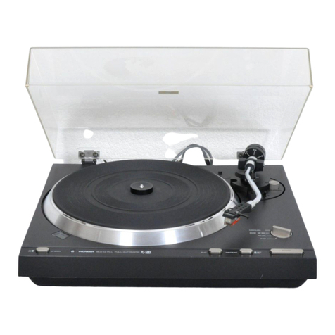
Pioneer
Pioneer PL-L70 User manual

Pioneer
Pioneer PL-05 User manual

Pioneer
Pioneer pl-510 KLT User manual

Pioneer
Pioneer PL-55DX User manual

Pioneer
Pioneer PL-12D User manual

Pioneer
Pioneer PL-A45 User manual

Pioneer
Pioneer Super Tuner III D DEH-P4800MP User manual

Pioneer
Pioneer PL-560 User manual
Pioneer
Pioneer PL-Z93 User manual

Pioneer
Pioneer PL-71 User manual

Pioneer
Pioneer XDJ-1000 User manual