PIPER AIRCRAFT
PA-32-301/301T
MAINTENANCE MANUAL
LISTOF ILLUSTRATIONS
FIGURE NO. SUBJECT GRID NO.
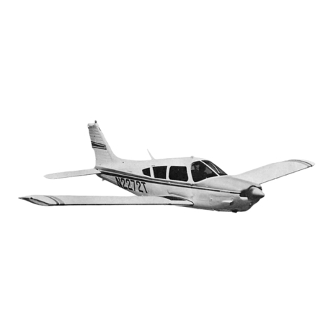
6-1. Three Viewof PA-32-301 1B16
6-2. Three Viewof PA-32-301T 1B17
6-3. Station Reference Lines (PA-32-301) 1B19
6-4. Station Reference Lines(PA-32-301T) 1B20
6-5. AccessPlates and Panels 1B21
7-1. Jacking 1B24
8-1. LevelingAirplane 1C3
8-2. Weighing IC4
11 1-. Placards and Decals 1C13
12-1. Fuel Filter Bowland Screen 1C18
12-2. Servicing Points IC22
12-3. Main Gear Oleo Struts (Cut-Away View) 1D2
12-4. Lubrication Chart (Landing Gear, Main) 1DII
12-5. Lubrication Chart (Landing Gear, Nose) ID12
12-6. Lubrication Chart (Control System) ID13
12-7. Lubrication Chart (Air Conditioning Condenser) ID16
12-8. Lubrication Chart (Cabin Door, BaggageDoor
and Seat) ID17
12-9. Lubrication Chart (Power Plant, Propeller and
Control Pivot Points) 1D18
12-10. LubricationChart (Back-UpExtenderand FuelSelector) ID19
20-1. Torque Wrench Formula 1D23
20-2. Method of Installing Rod End Bearings 1D23
20-3. Cherrylock Rivet Removal 1D24
20-4. Hose Line Markings IE2
20-5. Flareless-TubeFittings IE3
20-6. Maximum DistanceBetweenSupports forFluid Tubing IE4
21-1. Cabin Heater. Defrostersand Fresh Air System
(PA-32-301) IE
14
21-2. Cabin Heater. Defroster and Fresh Air System
(PA-32-301T) 1E15
21-3. Air Conditioning System Installation (Typical) 1E23
21-4. ServiceValves 1F4
21-5. Test Gauge and Manifold Set 1F5
21-6. Manifold Set Operation 1F6
21-7. Leak Test Hookup 1F7
21-8. Evacuation Hookup 1F9
21-9. Charging Stand IFII
21-10. Charging Hookup 1F13
21-11. Compressor and Fabricated Oil Dipstick IF17
21-12. Compressor and Alternator Belt Installation 1F18
21-13. Magnetic Clutch 1F20
21-14. Condenser Air Scoop Installation 1F24
21-15. Expansion Valve 1GI
21-16. Components Installation 1G3
21-17. Air Conditioning WiringSchematic (Early Models) 1G4
21-18. Air Conditioning WiringSchematic (Later Models) IG5
Introduction
Page -8
1A9 Revised:August 11,1983
