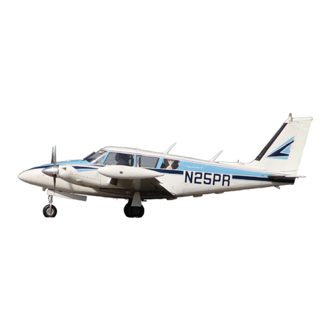
Piper SEMINOLE PA-44-180 User manual

SEMINOLE
MAINTENANCE MANUAL
CARD 1 OF 4
PA-44-180 SEMINOLE
PA-44-180T TURBO SEMINOLE
PIPER AIRCRAFT CORPORATION
(PART NUMBER 761 664) June 20.1995
1A1

INTRODUCTION.
This PIPER AIRCRAFT Maintenance Manual is prepared in accordance with the GAMA (General Aviation
Manufacturers Association) format. This maintenance manual is divided into various Groups which enable a
broad separation of contents (Chapters) within each group.
The various Chapters are broken down into major systems such as Electrical Power, Flight Controls, Fuel,
Landing Gear, etc. The System/Chapters are arranged more or less alphabetically rather than by precedence or
importance. All System/Chapters are assigned a number, which becomes the first element of a standardized
numbering system. Thus the element "32" of the number series 32-00-00 refers to the System/Chapter on
"Landing Gear". All information pertaining to the landing gear will be covered in this System/Chapter.
The major System/Chapters are then broken down into Sub-System/Sections. These sections are identified by
the second element of the standardized numbering system. The number "40" of the basic number series 32-40-00
is for the "Wheels and Brakes" portion of the landing gear.
The individual units within a Sub-System/Section may be identified by a third element of the standardized
numbering system, such as 32-40-01. This number could be assigned by the manufacturer to fit the coverage
requirements of the publication.
Example:
CHAPTER/SYSTEM SUB-SYSTEMS
LANDING GEAR WHEELS AND BRAKES
32-40-01
INDIVIDUAL UNITS
NOSE WHEEL REMOVAL
This manual does not contain hardware callouts for installation. Hardware callouts are only indicated where a
special application is required. To confirm the correct hardware used, refer to the PA-44 Parts Catalog P/N 761
663, and FAR 43 for proper utilization.
WARNINGS, CAUTIONS, and NOTES are used throughout this manual to emphasize important information.
— WARNING —
OPERATING PROCEDURES, PRACTICES, ETC., WHICH MAY RESULT IN
PERSONAL INJURY OR LOSS OF LIFE IF NOT CAREFULLY FOLLOWED.
— CAUTION —
OPERATING PROCEDURES, PRACTICES, ETC., WHICH IF NOT
STRICTLY OBSERVED MAY RESULT IN DAMAGE TO EQUIPMENT.
— Note —
An operating procedure, condition, etc., which is essential to emphasize.
PA-44-180/180T
AIRPLANE MAINTENANCE MANUAL
Introduction
Page -1
Revised: May 15, 1989
1A2
PIPER AIRCRAFT

VENDOR PUBLICATIONS.
ENGINE:
Overhaul Manual = TEXTRON LYCOMING - OVERHAUL MANUAL
DIRECT DRIVE ENGINE - P/N 60294-7
Textron Lycoming Division
Williamsport, Pa 17701
Parts Catalog = TEXTRON LYCOMING — O-360 AND LO-360 E SERIES - P/N PC-123
TEXTRON LYCOMING — TO-360 AND LTO-360 E SERIES - P/N PC-124
TEXTRON LYCOMING — O-360 AND LO-360 A SERIES - P/N PC306-5
Textron Lycoming Division
Williamsport, Pa. 17701
Operators Handbook = TEXTRON LYCOMING O-360 AND LO-360 E SERIES - P/N 60297-25;
TEXTRON LYCOMING TO-360 AND LTO-360 E SERIES - P/N 60297-26;
TEXTRON LYCOMING O-360 AND LO-360 A SERIES - P/N 60297-12;
AIRCRAFT ENGINES
Textron Lycoming Division
Williamsport, Pa 17701
PROPELLER:
Overhaul Instructions = HARTZELL COMPACT CONSTANT SPEED
and FEATHERING PROPELLER - P/N 117-D
Hartzell Propeller Inc.
Piqua, Ohio 45356
MAGNETOS:
Installation, Operation
and Maintenance
Instructions = D-2000 and D-2200 SERIES MAGNETO
IGNITION, SYSTEM - P/N L-928
Bendix Electrical Components Division
Sidney, New York 13838
4200 SERIES MAGNETOS
IGNITION, SYSTEM - P/N L-1199, L-1037
Slick Electro, Inc.
Rockford, Illinois 61104
TURBOCHARGERS:
Overhaul Manual = OVERHAUL MANUAL FOR
AIRCRAFT TURBOCHARGERS
VALVES AND CONTROLLERS
NUMBER TP20-0120-l
Airesearch Industrial Division
3201 Lomitor Blvd.
Torrance, Calif. 90505
PA-44-180/180T
AIRPLANE MAINTENANCE MANUAL
Introduction
Page -2
Revised: May 15, 1989
1A3
PIPER AIRCRAFT

VENDOR PUBLICATIONS. (cont)
RADAR ALTIMETER:
Maintenance KING KRA-10 MAINTENANCE/OVERHAUL
Instructions = MANUAL NUMBER 006-5152-00
King Radio Corporation
400 North Rogers Road
Olathe, Kansas 66061
BONZER MK 10X
Bonzer Incorporated
90th and Cody
Overland Park, Kansas 66214
Installation Manual = INSTALLATION MANUAL
NUMBER 006-0152-00
King Radio Corporation
400 North Rogers Road
Olathe, Kansas 66061
AUTOFLIGHT:
Manufacturer = EDO-AIRE MITCHELL or KING RADIO CORPORATION
KFC-150 P.O.Box 610 400 North Rogers Road
Mineral Wells, Texas 76067 Olathe, Kansas 66061
FUEL CELLS:
Maintenance= LORAL, Engineered Fabrics (or) Goodyear Aerospace Corp.
669 Goodyear Street Engineered Fabrics Division
Rockmart, Georgia 30153-0548 Rockmart, Georgia 30153
PIPER PUBLICATIONS.
AUTOFLIGHT:
AutoControl IIIB
Service Manual = Piper P/N 761 502
AutoControl IIIC
Service Manual = Piper P/N 761 602
PA-44-180/180T
Parts Catalog = Piper P/N 761 663
Inspection Reports = Piper P/N 230 963
Programmed Inspection
Manual = Piper P/N 761 733
PA-44-180/180T
AIRPLANE MAINTENANCE MANUAL
Introduction
Page -3
Revised: May 15, 1989
1A4
PIPER AIRCRAFT

AEROFICHE EXPLANATION AND REVISION STATUS
The Maintenance Manual information incorporated in this set of Aerofiche cards has been arranged in
accordance with the general specifications of Aerofiche adopted by the General Aircraft Manufacturer's
Association, (GAMA). The information compiled in this Aerofiche Maintenance Manual will be kept current by
revisions distributed periodically. These revisions will supersede all previous revisions and will be complete
Aerofiche card replacements and shall supersede Aerofiche cards of the same number in the set.
Conversion of Aerofiche alpha/numeric code numbers:
First number is the Aerofiche card number.
Letter is the horizontal line reference per card.
Second number is the vertical line reference per card.
Example: 2J16 = Aerofiche card number two of given set, Grid location J16.
To aid in locating the various chapters and related service information desired, the following is provided:
1. A complete manual System/Chapter Index Guide is given for all fiche in this set.
2. A complete list of Illustrations is for all fiche in this set following System/Chapter Index.
3. A complete list of Charts is for all fiche in this set following list of illustration.
4. A complete list of paragraph titles and appropriate Grid location numbers is given at the beginning of each
Chapter relating to the information within that Chapter.
5. Identification of Revised Material:
Revised text and illustrations are indicated by a black vertical line along the left-hand margin of the frame,
opposite revised, added or deleted material. Revision lines indicate only current revisions with
changes, additions to or deletions of existing text and illustrations. Changes in capitalization, spelling,
punctuation, indexing, the physical location of the material or complete page additions are not
identified by revision lines.
A reference and record of the material revised is included in each chapter's Table of Contents/Effectivity.
The codes used in the effectivity columns of each chapter are defined as follows:
TABLE OF CONTENTS/EFFECTIVITY CODES
Original Issue: None
First Revision: Revision Indication, ( 1R Month-Year)
Second Revision: Revision Indication, (2R Month-Year)
All subsequent revisions will follow with consecutive revision numbers
such as 3R, 4R, etc., along with the appropriate month-year
Added Subject: Revision Identification, (A Month-Year)
Deleted Subject: Revision Identification, (D Month-Year)
6. Revisions to this Maintenance Manual 761 664 issued May 1, 1978 are as follows:
PA-44-180/180T
AIRPLANE MAINTENANCE MANUAL
Introduction
Page -4
Revised: May 15, 1989
1A5
PIPER AIRCRAFT
AEROFICHE EXPLANATION AND REVISION STATUS (cont)
Effectivity Publication Date Aerofiche Card Effectivity
ORG791212 December 12, 1979 1, 2, and 3
PR800822 August 22, 1980 1, 2, and 3
PR810223 February 23, 1981 1, 2, and 3
PR810824 August 24, 1981 1, 2, and 3
PR820826 August 26, 1982 1, 2, and 3
PR820909 September 9, 1982 1, 2, and 3
PR830103 January 3, 1983 1, 2, and 3
PR840326 March 26, 1984 1, 2, and 3
IR860730 July 30, 1986 (Interim) 1
PR890515 August 3, 1989 1, 2, 3 and 4
PR950620 August 10, 1995 1, 2, 3 and 4
PA-44-180/180T
AIRPLANE MAINTENANCE MANUAL
Introduction
Page -5
Revised: June 20, 1995
1A6
PIPER AIRCRAFT

GAMA SYSTEM/CHAPTER INDEX GUIDE
SYST SUB-SYST AEROFICHE
CHAP SECTION TITLE GRID NO.
4AIRWORTHINESS 1A18
5 TIME LIMITS/MAINT CHECKS 1A21
6 DIMENSIONS AND AREAS 1B14
7 LIFTING AND SHORING 1C1
8 LEVELING AND WEIGHING 1C5
9TOWING AND TAXIING 1C10
10 PARKING AND MOORING 1C14
11 REQUIRED PLACARDS 1C17
12 SERVICING 1C22
20 STANDARD PRACT - AIRFRAME 1E2
21 ENVIRONMENTAL SYSTEM 1E12
22 AUTOFLIGHT 1H21
23 COMMUNICATIONS 1H24
24 ELECTRICAL POWER 1I10
25 EQUIPMENT / FURNISHINGS 1J12
26 FIRE PROTECTION 1J17
27 FLIGHT CONTROLS 1J24
28 FUEL 2A18
29 HYDRAULIC POWER 2B17
30 ICE AND RAIN PROTECTION 2D1
32 LANDING GEAR 2F13
PA-44-180/180T
AIRPLANE MAINTENANCE MANUAL
Introduction
Page -6
Revised: May 15, 1989
1A7
PIPER AIRCRAFT

GAMA SYSTEM/CHAPTER INDEX GUIDE (cont)
SYST SUB-SYST AEROFICHE
CHAP SECTION TITLE GRID N0.
33 LIGHTS 2I6
34 NAVIGATION & PITOT/STATIC 2I16
35 OXYGEN 2J7
37 VACUUM 2K6
39 ELECTRICAL/ELECTRONIC PANELS AND
MULTI-PURPOSE PARTS 2K19
5l STRUCTURES 2L7
52 DOORS 3A18
55 STABILIZERS 3B8
56 WINDOWS 3B22
57 WINGS 3C10
61 PROPELLER 3D1
71 POWER PLANT 3D21
73 ENGINE FUEL SYSTEM 3F1
74 IGNITION 3F16
77 ENGINE INDICATING 3H1
78 EXHAUST 3H19
79 OIL 3I1
80 STARTING 3I11
81 TURBINES 3J1
91 CHARTS AND WIRING DIAGRAMS 4A18
PA-44-180/180T
AIRPLANE MAINTENANCE MANUAL
Introduction
Page -7
Revised: May 15, 1989
1A8
PIPER AIRCRAFT

LIST OF ILLUSTRATIONS
FIGURE NO. SUBJECT GRID NO.
6-1. Three View 1B19
6-2. Station References 1B20
6-3. Access Plates and Panels 1B22
7-1. Jacking 1C4
8-1. Leveling Airplane 1C8
8-2. Weighing 1C9
11-1. Placards and Decals (Sheet 1 of 2 1C19
11-1. Placards and Decals (Sheet 2 of 2) 1C20
11-2 Placards and Decals (S/N 4495001 and up) 1C21
12-1. Service Points 1D1
12-2. Lubrication Chart - Landing Gear, Main 1D15
12-3. Lubrication Chart - Landing Gear, Nose 1D17
12-4. Lubrication Chart - Control System, Part 1 1D19
12-5. Lubrication Chart - Cabin Door, Baggage Door
and Seats 1D20
12-6. Lubrication Chart - Control System, Part 2 1D21
12-6. Lubrication Chart - Control System, Part 2 (cont.) 1D22
12-7. Lubrication Chart - Power Plant and Propeller 1D23
20-1. Torque Wrench Formula 1E4
20-2. Method of Installing Rod End Bearings 1E5
20-3. Cherrylock Rivet Removal 1E6
20-4. Identification of Aircraft Fluid Lines 1E8
21-1. Cabin Environmental System Installation 1E24
21-2. Heater and Combustion Air Blower Assembly 1F1
21-3. Diagrammatic Cutaway of Heater to Show Whirling
Flame Action 1F2
21-4. Fuel Regulator and Shutoff Valve 1F3
21-5. Top View - Duct Switch 1F3
21-6. Intake Valve and Switches 1F4
21-7. Wiring Diagram (Heater) 1F8
21-8. Primary Power Circuit (Heater) 1F9
21-9. Starting Power Circuit (Heater) 1F10
21-10. Spark Plug Fixture (Heater) 1F12
21-11. Wiring - Test Setup (Heater) 1F12
21-12. Spark Plug Gap Adjustment (Heater) 1F13
21-13. Ignition Unit Assembly (Heater) 1F17
21-14. Test Setup for Fuel Regulator and Shutoff Valve (Heater) 1F20
21-15. Heater Fuel Pump 1F21
21-16. Suggested Design for Seal Plates, Plugs, and Caps for
Combustion Tube leakage Test 1G1
21-17. Test Setup for Combustion Air Pressure Switch 1G1
21-18. Exploded View of Heater Assembly 1G6
PA-44-180/180T
AIRPLANE MAINTENANCE MANUAL
Introduction
Page -8
Revised: June 20, 1995
1A9
PIPER AIRCRAFT

LIST OF ILLUSTRATIONS (cont)
FIGURE NO. SUBJECT GRID NO.
PA-44-180/180T
AIRPLANE MAINTENANCE MANUAL
Introduction
Page -9
Revised: June 20, 1995
1A10
21-19. Exploded View - Combustion Air Blower and Motor
Assembly 1G8
21-20. Suggested Setup of Heater Operation Test 1G10
21-21. Wiring Connections for Heater Operation Test 1G10
21-22. Spark Plug Gap Adjustment Tool 1G13
21-23. Heater Hourmeter Installation 1G14
21-24. Air Conditioning System Installation
(PA-44 - 180T S/N 44-8107027 and up) 1G21
21-25. Test Gauge and Manifold Set 1H2
21-26. Manifold Set Operation 1H3
21-27. Leak Test Hookup 1H4
21-28. Evacuation Hookup 1H6
21-29. Charging Stand 1H8
21-30. Charging Hookup 1H9
21-31. Top Dead Center Casting Mark (Sankyo Compressor) 1H12
21-32. Rotation of Clutch Front Plate (Sankyo
Compressor Oil Check) 1H12
21-33. Condenser Installation 1H15
21-34. Expansion Valve 1H17
21-35. Components Installation 1H19
23-1. Communications Components Corporation ELT Schematic 1I3
23-2. ELT Using Fixed Aircraft Antenna (Narco) 1I4
23-3. ELT Portable Folding Antenna (Narco) 1I4
23-4. Narco ELT 10 Emergency Locator Transmitter Schematic 1I5
23-5. Narco ELT 910 Emergency Locator Transmitter Schematic 1I6
23-6 ELT 910 BatteryPack (SN’s 4495008 and up) 1I7
24-1. Lamp Bank load 1I22
24-2. Battery Box 1I24
24-3. Electrical Component Location (Lamar Model No. B-00288-1)
(S/N 44-7995001 thru 44-8195026 and all PA-28- 180T’s) 1J4
24-4. Lamar Model No. B-00288-1 Regulator Diagram
(S/N 44-7995001 thru 44-8195026 and all PA-28- 180T’s) 1J4
24-5. Testing Lamar Model No. B-00288-1 Regulator
(S/N 44-7995001 thru 44-8195026 and all PA-28- 180T’s) 1J6
24-6. Adjusting Lamar Model No. B-00288-1 Regulator
(S/N 44-7995001 thru 44-8195026 and all PA-28- 180T’s) 1J7
24-7. Electrical Component Location (Lamar Model No. B-00392-1)
(S/N 4495001 and up) 1J9
24-8 Lamar B-00392-1 Regulator Overvoltage Test Method 1J10
25-1. Seat Back Lock 1J14
25-2 Lumbar Seat Bladder Installation 1J16
27-1. Rod End Bearing Installation: 1K4
PIPER AIRCRAFT

LIST OF ILLUSTRATIONS (cont)
FIGURE N0. SUBJECT GRID NO.
PA-44-180/180T
AIRPLANE MAINTENANCE MANUAL
Introduction
Page -10
Revised: June 20, 1995
1A11
27-2. Control Cable Inspection Technique 1K5
27-3. Cable Wear Pattern 1k6
27-4. Internal Cable Wear 1K6
27-5. Pulley Wear Patterns 1K8
27-6. Control Column Assembly 1K13
27-7. Flex (Universal) Joint Assembly 1K15
27-8. Aileron Controls 1K17
27-9. Bellcrank Rigging Tool 1K19
27-10. Aileron Rigging 1K20
27-11 Rudder Controls 1K23
27-12. Clamping Rudder Pedals 1L1
27-13 Rudder Rigging Tool 1L1
27-14. Rudder Rigging 1L1
27-15. Rudder Travel Adjustments 1L2
27-16. Rudder Trim Controls 1L4
27-17. Rudder Pedal Assembly 1L7
27-18. Stabilator Controls 1L9
27-19. Stabilator Rigging 1L11
27-20. Stabilator Travel Adjustments 1L13
27-21. Methods of Securing Trim Cables 1L13
27-22. Stabilator Trim Controls 1L15
27-23. Wrapping Trim Barrels 1L18
27-24. Stabilator Trim Screw Adjustment 1L18
27-25. Flap Controls 1L20
27-26. Flap Step Adjustment 1L22
27-27. Flap Rigging Tool 1L24
28-1. Fuel System Installation 2A22
28-2. Fuel Cell Installation 2B2
28-3. Locking Fuel Cap Assembly 2B9
28-4. Gascolator Assembly 2B11
28-5. Fuel Selector Valve 2B12
28-6. Fuel Gauge 2B15
28-7. Fuel Pressure Gauge and Calibration 2B16
28-7A. Fuel Pressure Gauge and Calibration (S/N 44-95001 & up) 2B16
29-1. Schematic Diagram of Prestolite Hydraulic System 2B21
29-2. Schematic Diagram of Oildyne Hydraulic System 2B22
29-3. Exploded View of Prestolite Hydraulic Pump/Reservoir, 2C8
29-4. Test and Adjustments of Hydraulic Pump 2C11
29-5. Oildyne Hydraulic Pump (Sheet 1 of 2) 2C14
29-5. Oildyne Hydraulic Pump (Sheet 2 of 2) 2C15
29-6. Nose Gear Actuating Cylinder 2C18
29-7. Main Gear Actuating Cylinder 2C20
PIPER AIRCRAFT

LIST OF ILLUSTRATIONS (cont)
FIGURE N0. SUBJECT GRID NO.
PA-44-180/180T
AIRPLANE MAINTENANCE MANUAL
Introduction
Page -11
Revised: May 15, 1989
1A12
29-8. End Gland Locking Device (Main Gear) 2C20
29-9. Hydraulic Lines Installation 2C23
30-1. Pneumatic Deice System Installation 2D9
30-2. Deice Control Panel Installation 2D16
30-3. Electric Prop Deice System Installation 2E9
30-3. Electric Prop Deice System Installation (cont) 2E10
30-4. Suggested Use of Dial Indicator 2E13
30-5. Centering of Brushes on Slip Rings 2E13
30-6. Modular Brush Assembly Alignment 2E14
30-7. Measuring Brush Assemblies 2E15
30-8. Brush Module Assembly 3E2011 2E16
30-9. Modular Brush Assembly 3E2090-l 2E16
30-10. Installation of Deicer Boots 2E19
30-11. Typical Deicer Boot Scaler Application 2E22
30-12. Wrinkled Deicer 2E22
30-13. Deicer Wiring Harness Installation (Typical) 2F1
30-14. Wing Ice Lighting System 2F3
30-15. Ice Detection System 2F6
30-16. Heated Pitot and Heated Lift Detector Installation (PA-44-180T) 2F7
32-1. Main Gear Oleo Strut Assembly 2G1
32-2. Main Gear Service Tolerances 2G3
32-3. Main Gear Installation 2G8
32-3. Main Gear Installation (cont) 2G9
32-4. Aligning Main Gear 2G13
32-5. Nose Gear Oleo Strut Assembly 2G15
32-6. Nose Gear Installation 2G17
32-7. Nose Gear Service Tolerances 2G19
32-8. Nose Gear Downlock and Eccentric Bushing Installation 2G24
32-9. Nose Gear Adjustment 2H2
32-10. Clamping Rudder Pedals in Neutral Position 2H4
32-11. Rudder Pedals at Neutral Angle 2H4
32-12. Mechanical Nose Gear Door Mechanism 2H6
32-13. Nose Wheel Assemblies 2H8
32-14. Main Wheel Assembly 2H10
32-15. Wheel Brake Assembly 2H12
32-16. Removal and Installation of Anchor Bolts 2H13
32-17. Brake Installation 2H15
32-18. Parking Brake Valve Assembly 2H16
32-19. Brake Cylinder (1700) 2H17
32-20. Brake Cylinder (10-27) 2H17
32-21. Brake Cylinder (10-30) (Toe Brake) 2H18
32-22. Toe Brake Installation 2H21
PIPER AIRCRAFT

LIST OF ILLUSTRATIONS (cont)
FIGURE NO. SUBJECT GRID NO.
PA-44-180/180T
AIRPLANE MAINTENANCE MANUAL
Introduction
Page -12
Revised: June 20, 1995
1A13
32-23. Adjustment of Main Gear Down Limit Switch 2H23
32-24. Adjustment of Nose Gear Down Limit Switch 2H23
32-25. Throttle Warning Switches (Without Mute Switch) (Sheet 1 of 2) 2I2
32-25. Throttle Warning Switches (With Mute Switch) (Sheet 2 of 2) 2I2
34-1. Pitot-Static System Installation 2I20
35-1. Fixed - Oxygen System 2J10
35-2. Portable - Oxygen System 2J11
35-3. Test Apparatus for Testing Oxygen System 2J14
35-4. Oxygen Tubing Installations 2J15
35-5. Installation of Swageloc Fittings 2J18
37-1. Vacuum System Installation 2K9
37-2. Vacuum Regulator 2K11
39-1. Annunciator Panel Installation 2K23
39-1A Annunciator Panel Installation (PA-44-180, S/N 44-95001 and up) 2K24
39-2. Electric Clock Installation 2L2
39-2. Electric Clock Installation (cont) 2L3
51-1. Skin Materials and Thickness (Sheet 1 of 2) 2L11
51-1. Skin Materials and Thickness (Sheet 2 of 2) 2L12
51-2. Baggage Compartment Inspection Hole Cutout Details 2L13
51-3 Surface Scratches, Abrasions or Ground-in-Dirt 2L17
51-4. Deep Scratches, Shallow Nicks and Small Holes 2L18
51-5. Mixing of Epoxy Patching Compound 2L18
51-6. Welding Repair Method 2L19
51-7. Repairing of Cracks 2L19
51-8. Various Repairs 2L20
51-9. Repair of Stress Lines 2L22
51-10. Repair of Impacted Damage 2L22
52-1. Door Installation 3A21
52-1a. Door Snubber Installation 3A23
52-2. Fabricated Tool for Baggage Door Lock 3A24
52-3. Emergency Exit Installation 3B2
55-1. Stabilator Installation 3B11
55-2. Stabilator Balance Configuration 3B12
55-3. Vertical Fin Installation 3B13
55-4. Rudder Installation 3B15
55-5. Rudder Balancing 3B16
56-1. Windshield Installation 3C9
56-2. Side Window Installation 3C3
57-1. Wing Installation 3C14
57-2. Aileron and Flap Installation 3C18
57-3. Aileron Balancing 3C20
61-1. Typical Nicks and Removal Method 3D4
PIPER AIRCRAFT

LIST OF ILLUSTRATIONS (cont)
FIGURE N0. SUBJECT GRID NO.
PA-44-180/180T
AIRPLANE MAINTENANCE MANUAL
Introduction
Page -13
Revised: May 15, 1989
1A14
61-2. Propeller Installation 3D5
61-3. Propeller Governor 3D7
61-4. Adjustment of Propeller Control 3D7
61-5. Synchrophaser System Installation 3D9
61-6. Pulse Generator Assembly 3D11
61-7. Backup Test of Pulse Generator 3D14
61-8. Propeller Unfeathering System (PA-44-180, S/N 44-95001 and up) 3D17
71-1. Engine and Shock Mount Installation (Sheet 1 of 3) (S/n’s 44-7995001 3E8
thru 44-8195026)
71-1. Engine and Shock Mount Installation (Sheet 2 of 3) (S/n’s 4495001 &up) 3E9
71-1. Engine and Shock Mount Installation (Sheet 3 of 3) (S/n’s 44-8107001
thru 44-8207020) 3E10
71-2. Engine Cowling Installation 3E13
71-3. Cowl Flap Installation 3E13
71-4. PA-44-180 Induction System 3E15
71-5. PA-44-180T Induction System 3E18
73-1. Carburetor 3F3
73-2. Engine Primer System (PA-44-180) 3F6
73-3. Fuel System Schematic (PA-44-180T) 3F6
73-3a. Electric Primer System (PA-44-180, S/N 44-95001 and up) 3F7
73-4. Engine Primer System (PA-44-180T) 3F8
73-5. Adjustment of Engine Controls (Sheet 1 of 2) (PA-44-180, s/n’s
4495001 thru 44-8195026, and PA44-180T, s/n’s 44-810701 & up) 3F10
73-5. Adjustment of Engine Controls (Sheet 1 of 2) (PA-44-180, s/n’s
44-7195001 & up) 3F11
74-1. Height of Spring in Distributor Block Tower 3F21
74-2. Contact Points 3F21
74-3. Engine Timing Marks 3F23
74-4. Timing Light Connected to Magneto 3F23
74-5. Timing Marks on Magneto Rotor 3F24
74-6. Painted tooth Centered in Timing Window 3G1
74-7. Timing Mark on Rotor Aligned with Pointer 3G1
74-8. Timing Light Connected to Magneto and Breakers 3G4
74-9. Cam End View of Magneto 3G5
74-10. Removing Impulse Coupling 3G7
74-11. Checking Flyweight to Stop Pin Clearance 3G7
74-12. Stop Pin Installation Dimension 3G7
74-13. Checking Flyweight Axial Wear with Drill Shank 3G8
74-14. Checking Flyweight Radial Wear with Gauge 3G8
74-15. Points of Coupling Body Wear 3G9
74-16. Acceptable and Deformed Coupling Springs 3G9
74-17. Checking Impulse Coupling for Magnetization 3G11
74-18. Orientation of Spring in Coupling Body 3G11
PIPER AIRCRAFT

LIST OF ILLUSTRATIONS (cont)
FIGURE N0. SUBJECT GRID NO.
PA-44-180/180T
AIRPLANE MAINTENANCE MANUAL
Introduction
Page -14
Revised: May 15, 1989
1A15
74-19. Lifting Inner End of Spring 3G11
74-20. Checking Harness Leads Continuity 3G13
74-21. Checking Harness Leads Insulation Resistance 3G13
74-22. Modified Pliers 3G13
74-23. Removing Spring From Lead Assembly 3G13
74-24. Assembly Tool 3G15
74-25. Using Assembly Tool 3G15
74-26. Ferrule Positioned Under Braid 3G16
74-27. Ferrule Seating Tool 3G16
74-28. Position of 11-8627 Kit and Contact Spring at Start
of Installation 3G17
74-29. Position of 11-8627 Kit and Contact Spring After
Installation 3G17
74-30. Lubricating Sleeve 3G17
74-31. Lubricating Ferrule Shoulder 3G17
74-32. Removing Spark Plug Frozen to Bushing 3G19
74-33. Magneto and Starter Switches 3G21
77-1. Engine Instrument Lines Installation 3H3
77-2. Electric Tachometer Installation 3H9
77-3. Cylinder Head Temperature Gauge Calibration (S/N 44-95001 and up) 3H12
77-4. EGT Probe Installation (PA-44-l80T) 3H16
78-1. Inspection of Mufflers 3H21
79-1. Oil Pressure Gauge Calibration (PA-44-180, S/N 44-95001 and up) 3I6
79-2. Oil Temperature Gauge Calibration (PA-44-180, S/N 44-95001 and up) 3I8
80-1. Exploded View of Gear Reduction Starter Motor 3I16
80-2. Turning Motor Commutator 3I19
80-3. Testing Motor Armature for Shorts 3I19
80-4. Testing Motor Fields for Grounds 3I19
80-5. No Load Test Hookup 3I19
80-6. Stall Torque Hookup 3I21
81-1. Schematic Diagram of Typical Turbocharger System 3J10
81-2. Turbocharger Installation 3J12
91-1. Tire Balancer Fixture 4B1
91-2. Control Surface Balancing Tool 4B11
91-3. Fabricated Aileron Bellcrank Rigging Tool 4B12
91-4. Fabricated Aileron and Flap Rigging Tool 4B13
91-5. Fabricated Stabilator Rigging Tool 4B14
91-6. Fabricated Rudder Rigging Tool 4B14
ELECTRICAL SCHEMATICS
— Note —
Refer to Card 4 Grid No. 4B21 for Electrical Schematic Index
PIPER AIRCRAFT

LIST OF CHARTS
CHART NO. SUBJECT GRID NO.
601 Leading Particulars and Principal Dimensions 1B16
1201 Thread Lubricants 1E1
2001 Maximum Distance Between Supports for Fluid Tubing 1E7
2101 Troubleshooting (Janitrol Heater) 1E17
2102 Blower System Wire Color Codes 1E22
2101 Inspection (Ignition Unit) 1F18
2104 Troubleshooting (Air Conditioner) 1G16
2105 Temperature Pressure Chart 1G22
2106 Aluminum Tubing Torque 1H1
2107 Evaporator Blower Motor Wire Codes 1H19
2401 Troubleshooting (Alternator) 1I14
2402 Troubleshooting (Battery) 1I19
2403 Alternator Belt Tension 1I23
2404 Hydrometer Reading and Battery Charge Percent 1J1
2701 Cable Tension Vs. Ambient Temperature 1K4
2702 Troubleshooting Control Surfaces 1K8
2801 Troubleshooting (Fuel System) 2A23
2802 Sender/Fuel Quantity Gauge Tolerances 2B15
2901 Leading Particulars, Hydraulic System 2B24
2902 Troubleshooting Hydraulic System 2C1
2903 Hydraulic Pump Motor Characteristics 2C6
3001 Troubleshooting (Pneumatic Deice System) 2D7
3002 Operating Pressures 2D11
3003 Materials and Supplies for Cold Repair 2D18
3004 Troubleshooting (Propeller Deicer System) 2D19
3005 Required Materials for Repair of Propeller Deicer 2E20
3006 Mixing of Materials 2E23
3007 Electrical Resistance 2E23
3201 Troubleshooting (Landing Gear) 2F18
3202 Toe-In, Toe-Out Correction 2G11
3401 Troubleshooting (Rate of Climb Indicator) 2I21
3402 Troubleshooting (Altimeter) 2I22
3403 Troubleshooting (Airspeed Tubes and Indicator) 2I23
3404 Troubleshooting (Magnetic Compass) 2J1
3501 Troubleshooting (Oxygen System) 2J12
3502 Oxygen System Limits 2J19
3503 Filling Pressure for Certain Ambient Temperatures 2J24
3504 Portable Oxygen System Component Limits 2K2
3701 Troubleshooting (Vacuum System) 2K10
3901 Troubleshooting (Annunciator Panel) 2K22
5101 List of Materials (Thermoplastic Repair) 2L14
6101 Propeller Torque Limits 3D4
PA-44-180/180T
AIRPLANE MAINTENANCE MANUAL
Introduction
Page -15
Revised: June 20, 1995
1A16
PIPER AIRCRAFT

LIST OF CHARTS (cont)
CHART NO. SUBJECT GRID NO.
PA-44-180/180T
AIRPLANE MAINTENANCE MANUAL
Introduction
Page -16
Revised: May 15, 1989
1A17
7101 Troubleshooting (Engine) 3D24
7301 Fuel Pressure Sender Test Specifications 3F12
7302 Troubleshooting (Fuel Pressure Gauge) 3F13
7401 Troubleshooting (Magneto) 3F18
7402 Coupling Torques 3G18
7701 Manifold Pressure Indicator (Troubleshooting) 3H6
7702 Tachometer (Troubleshooting) 3H7
7703 Cylinder Head Temperature (Troubleshooting) 3H11
7704 Exhaust Gas Temperature (Troubleshooting) 3H14
7901 Oil Pressure Sender Test Specifications 3I4
7902 Oil Pressure Gauge (Troubleshooting) 3I5
7903 Oil Temperature Indicators (Troubleshooting) 3I7
8001 Troubleshooting (Starter) 3I13
8002 Starting Motor Specifications 3I21
8101 Troubleshooting (Turbocharger) 3J3
9101 Flare Fitting Torques 4A20
9102 Recommended Nut Torques 4A21
9103 Decimal Conversions 4A23
9104 Decimal Equivalents of Drill Sizes 4A24
9105 List of Consumable Materials 4B2
9106 Metric Conversion Tables 4B7
9107 Electric Wire Coding 4B8
9108 Electric Symbols 4B16
9109 Electrical System Component Loads 4B19
PIPER AIRCRAFT

CHAPTER
AIRWORTHINESS
LIMITATIONS
PA-44-180/180T
AIRPLANE MAINTENANCE MANUAL
1A18
PIPER AIRCRAFT

AIRWORTHINESS LIMITATIONS.
GENERAL.
The airworthiness limitations is FAA approved and specifies inspections and maintenance required under Parts
43, 16 and 91.163 of the Federal Aviation Regulations.
The following limitations related to fatigue life of the airplane and its components have been established with
respect to the PA-44-l80/180T airplane:
1. The safe life of the airframe structure will be released when the information becomes available.
2. The safe life limit of the propeller blades is unlimited.
— Note —
Refer to the LIMITATIONS in the Pilot's Operating handbook and FAA Approved
Airplane Flight Manual for a detailed delineation of the flight limitations of the
airplane. The mandatory replacement time and or inspection intervals of life limited
parts are contained in Chapter 5 of this manual.
— END —
PA-44-180/180T
AIRPLANE MAINTENANCE MANUAL
4-01-00
Page 4-10
Revised: May 15, 1989
1A20
PIPER AIRCRAFT
Other manuals for SEMINOLE PA-44-180
1
This manual suits for next models
1
Table of contents
Other Piper Tools manuals

Piper
Piper PA-44-180 Seminole 1979 Technical specifications

Piper
Piper Cherokee Arrow II PA-28R-200 1973 User manual

Piper
Piper Archer III PA-28-181 User manual

Piper
Piper PA-32-301 Saratoga User manual

Piper
Piper PA-34-200T Seneca II User manual

Piper
Piper Cherokee Archer II Owner's manual

Piper
Piper APACHE PA-23-235 User manual

Piper
Piper TWIN COMANCHE PA-30 User manual

Piper
Piper Malibu Meridian PA-46-500TP User manual

Piper
Piper CHEROKEE ARROW 200 User guide