2011 NEW PRODUCTS
Please be sure to read before handling the product. Please refer to "safety instructions", "common safety instructions for products listed in this manual", "common safety instructions for ow controller" from page 24 through 35.
6
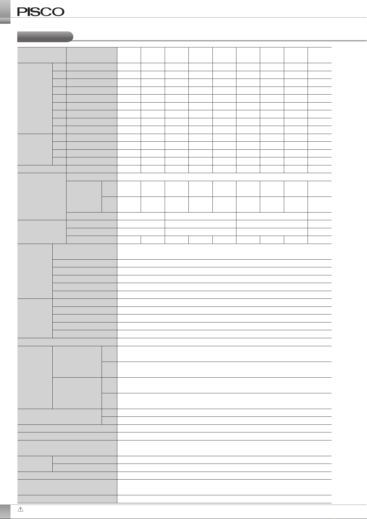
Specication
Item Full-scale ow 005 010 020 050 100 200 500 101 201
Flowrate
range
(*1)
005 500ml/min ●
010 1l/min ●
020 2l/min ●
050 5l/min ●
100 10l/min ●
200 20l/min ●
500 50l/min ●
101 100l/min ●
201 200l/min ●
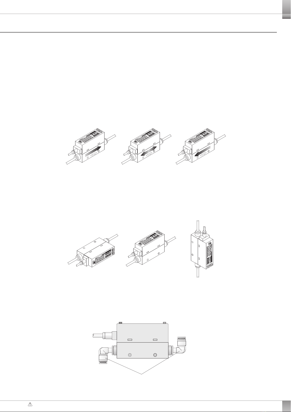
Port size
4
ø4mm Quick-fitting
●●●●●●
6
ø6mm Quick-fitting
●●●●●●●
8
ø8mm Quick-fitting
●●●
10
ø10mm Quick-fitting
● ●
Built-in needle valve
N (*9)●●●●●●●●●
Flowrate display
(*1) (*2)
Display method 4digits +4digits, 2color LCD
Display
range
F0~500
ml/min
0~1000
ml/min
0~2.00
l/min
0~5.00
l/min
0~10.00
l/min
0~20.0
l/min
0~50.0
l/min
0~100.0
l/min
0~200
l/min
R
-500~500
ml/min
-1000~1000
ml/min
-2.00~2.00
l/min
-5.00~5.00
l/min
-10.00~10.00
l/min
-20.0~20.0
l/min
-50.0~50.0
l/min
-100.0~100.0
l/min
-200~200
l/min
Minimum unit setting
1ml/min 0.01l/min 0.1l/min 1l/min
Accumulation
(*3)
Maxflowrate 9999999ml99999.99l999999.9l
9999999l
Mini. unit setting 1ml0.01l0.1l1l
Accumulated pulse output rate
5ml10ml0.02l0.05l0.1l0.2l0.5l1l2l
Working
condition
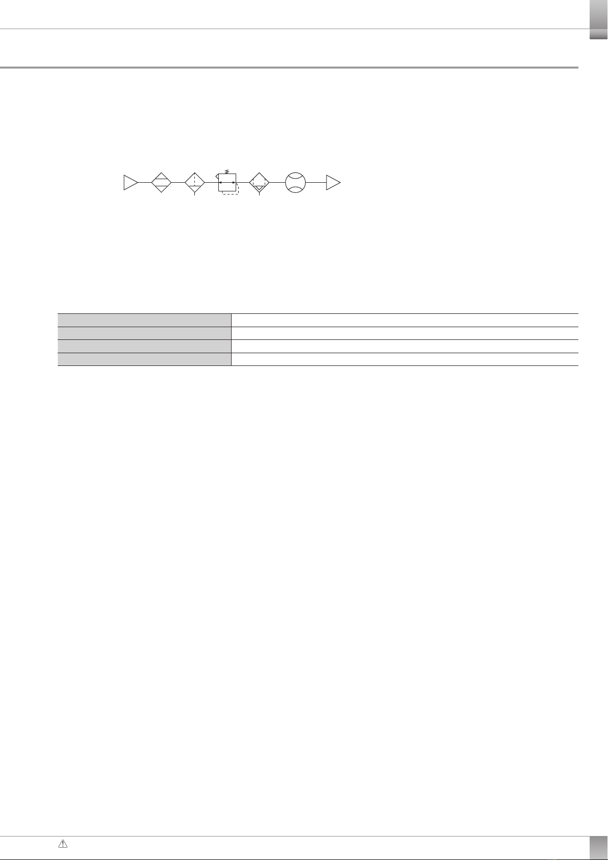
Fluid medium (*4) Clean air (JIS B8392-1.1.1to 5.6.2), Compressed air (JIS B8392-1.1.1to 1.6.2),
and nitrogen gas
Maxworking pressure 0.7MPa
Min working pressure -0.09MPa
Withstand pressure 1MPa
Ambient Temp. & humidity
0to 50ºC, max. 90%RH
Working fluid temp. 0to 50ºC (no dewcondensation)
Accuracy
Assured accuracy range
3~ 100%F.S.
Linearity (display/analog output)
Max±3%F.S. (Air vent for 2ndary side、25ºC)
Pressure characteristics
Max±5%F.S. (-0.09 to 0.7MPa, where air vent for 2ndary side is reference)
Temp. characteristics Max±0.2%F.S./ºC (15 to 35ºC, where 25ºC is reference)
Repeatability Max.±1%F.S.
Response time (*5) Max.50ms
Output
Switch output
N 2 points output (NPNopen collector output: max. 50mA, voltage drop: max. 2.4V)
P2points output (PNP open collector output: max. 50mA, voltage drop: max. 2.4V)
Analog output
V1voltage output 1to 5V (connected load impedance: min. 50kΩ)
A Current output 4to 20mA (connected impedance: 0to 300Ω)
Power supply voltage (*6)
V DC12 ~ 24V (10.8 ~ 26.4V)
A DC24V (21.6 ~ 26.4V)
Current consumption (*7)Max.50mA
Lead wire ø3.7 AWG26 equiv. x5core cable (connector joint), Insulator O.D. ø1.0mm
Functions Flowrate display, flowrate -peak hold, switch output, analog output, and other
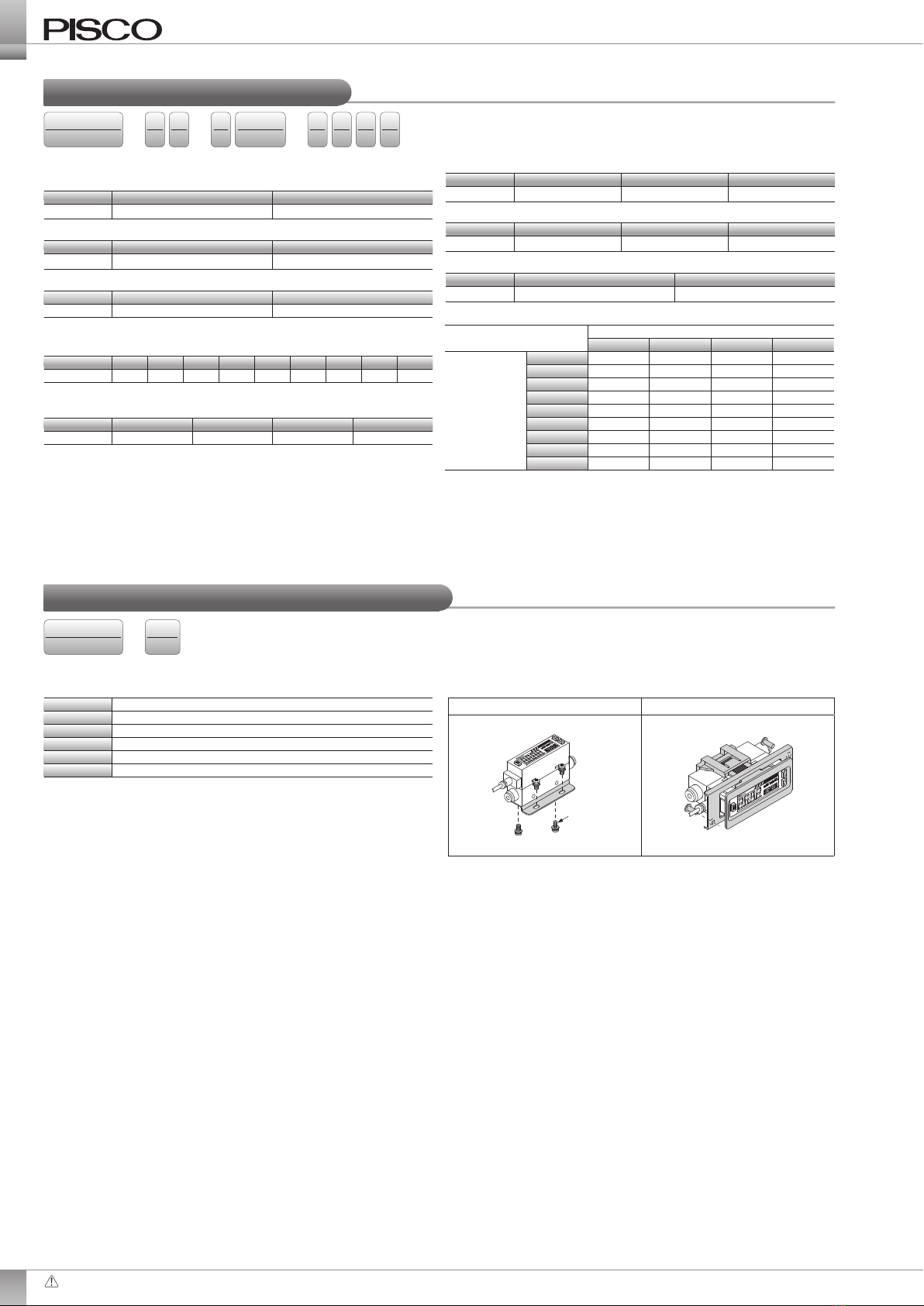
Installation Installing orientation Horizontal or vertical
Straight pipe introduction
Not required
Protective structure IEC standard: IP40
Protective circuit (*8)
Power supply and switch output reverse connection protections, and switch output
load short-circuit protection
EMC directive Conformity