Vacuum Generator VK
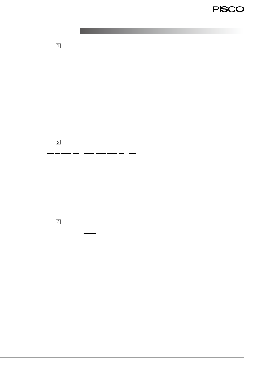
■ Model Designation (Example)
AVK 07
1/4
⑤
Vacuum port
①
Port orientation
③
Nozzle bore
H
②
Vacuum characteristics
B
⑨
Body color
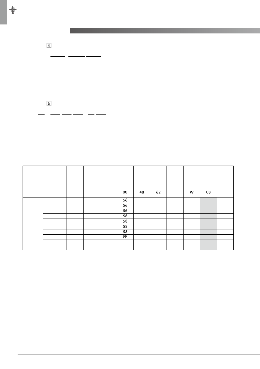
① Port orientation
③ Nozzle bore. (Combinations: A, C, E, G, J, L, P, Q, R, S, T and W)
Complex Vacuum
Generator
⑩
Number of stations
‒NW
⑪
Vacuum switch
W
④
Combinations Exhaust port
⑥
Air supply port
⑧
Solenoid valve type
② Vacuum characteristics
Nozzle bore. (Combinations: B, D, F, H, K and M)
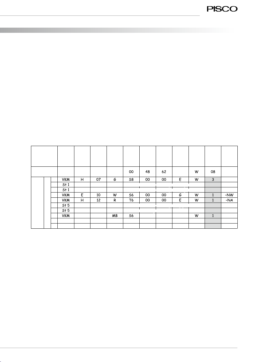
Code
A
Stand-alone type with double side port
Code
B
Stand-alone type with single side port
Code
MManifold type
Code
05
07
Nozzle
bore
0.5mm
0.7mm
H type
Vacuum level and Suction flow
(-91kPa, 7l/min[ANR] )
(-93kPa, 13l/min[ANR])
L type
Vacuum level and Suction flow
(-67kPa, 12l/min[ANR])
(-67kPa, 26l/min[ANR])
E type
Vacuum level and Suction flow
–
(-91kPa, 10.5l/min[ANR])
Air consumption
(11.5l/min[ANR])
(23l/min[ANR](17l/min[ANR]) )
Code
H
No code
Performance
High-vacuum type
Manifold-base alone
Code
L
Performance
Large-flow type
Rated supply pressure
72.5 psi (0.5MPa)
Code
E
Performance
High-vacuum at low air supply pressure type
Rated supply pressure
50 psi (0.35MPa)
Code
05
07
Nozzle
bore
0.5mm
0.7mm
H type
Vacuum level and Suction flow
L type
Vacuum level and Suction flow
E type
Vacuum level and Suction flow
–
Air consumption
(11.5l/min[ANR])
10
12
No code
1.0mm
1.2mm
(-93kPa, 27l/min[ANR])
(-93kPa, 38l/min[ANR])
(-67kPa, 40l/min[ANR])
(-67kPa, 50l/min[ANR])
(-91kPa, 21l/min[ANR])
(-91kPa, 27l/min[ANR])
(46l/min[ANR](34 l/min[ANR]) )
(70l/min[ANR](47 l/min[ANR]) )
Manifold-base alone
10
12
No code
1.0mm
1.2mm
Manifold-base alone
S
E
⑦
1/4
Rated supply pressure
72.5 psi (0.5MPa)
( ) ( () )
-26.8inHg, 0.25scfm -19.8inHg, 0.42scfm 0.41scfm
-27.6inHg, 0.46scfm -19.8inHg, 0.91scfm -27inHg, 0.37scfm 0.81scfm (0.60scfm)
-27.6inHg, 0.95scfm -19.8inHg, 1.40scfm -27inHg, 0.37scfm 1.63scfm (1.20scfm)
-27.6inHg, 1.33scfm -19.8inHg, 1.75scfm -27inHg, 0.95scfm 2.47scfm (1.67scfm)
※Suction flow of the vacuum port size with 5/32" O.D. and ø4mm may be different from the above values.
※Supply pressure is 72.5psi (0.5MPa)for H and L type and 50psi (0.35MPa)for E type.
※Air consumption values in ( ) represents that of E type.
※The values in the table are reference values only. Suction flow varies according to the vacuum system conditions;
vacuum port dia. or tube length.
-
25.5inHg, 0.19scfm
(-86.5kPa, 5.4l/min[ANR])
-
19.6inHg, 0.35scfm
(66.5kPa, 10l/min[ANR] )
0.41scfm
-
26.7inHg, 0.39scfm
(-
90.5kPa, 11l/min[ANR])
-
19.6inHg, 0.67scfm
(-66.5kPa, 19l/min[ANR])
-
25.5inHg, 0.30scfm
(-86.5kPa, 8.4l/min[ANR])
0.81scfm (0.60scfm)
(
23l/min[ANR](17l/min[ANR]))
-
26.7inHg, 0.67scfm
(-90.5kPa, 19l/min[ANR])
-
19.6inHg, 0.85scfm
(-66.5kPa, 24l/min[ANR])
-
25.5inHg, 0.54scfm
(-86.5kPa, 15.4l/min[ANR])
1.63scfm (1.20scfm)
(
46l/min[ANR](34l/min[ANR]))
-
26.7inHg, 0.85scfm
(-90.5kPa, 24l/min[ANR])
-
19.6inHg, 0.95scfm
(-66.5kPa, 27l/min[ANR])
2.47scfm (1.67scfm)
(
70l/min[ANR](47l/min[ANR]))
-
25.5inHg, 0.67scfm
(-86.5kPa, 19l/min[ANR])