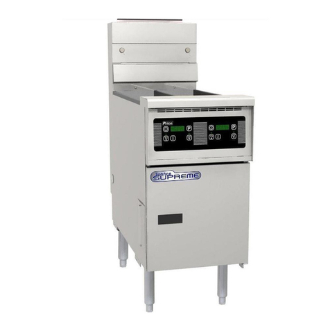
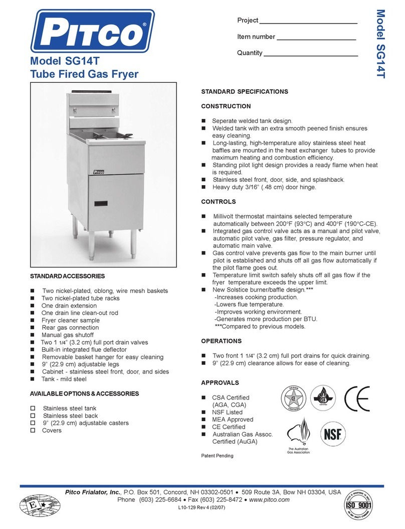
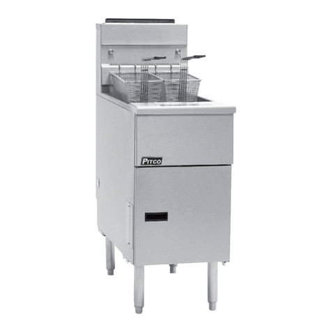
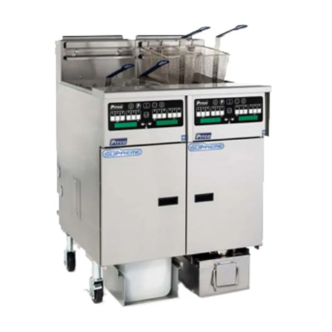
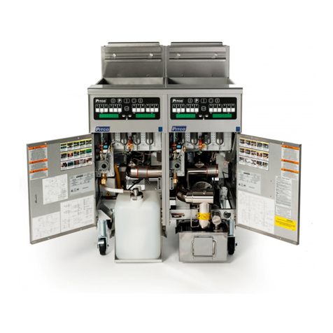
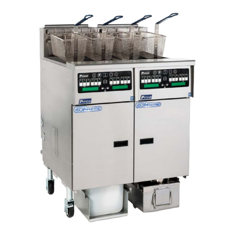
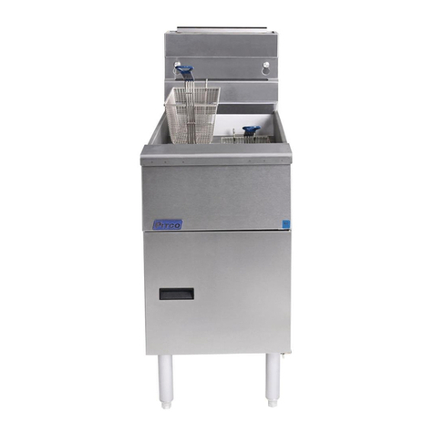
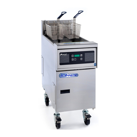
Pitco Solstice SE Series User manual

L22-330 R1 (10/12)
SolsticeElectricFryers
SESeries
ServiceManual

PitcoSolsticeElectricFryers
SESeriesServiceManual2
Notice
In the event of problems or questions about your order, contact the Pitco Frialator factory at (603) 225-6684.
In the event of problems or questions about your equipment, contact the Pitco Frialator Authorized Service and
Parts representative (ASAP) covering your area, or contact Pitco at the numbers listed above.
MAILINGADDRESS
Pitco Frialator
P.O. Box 501
Concord, NH 03302-0501
SHIPPINGADDRESS
Pitco Frialator
10 Ferry Street
Concord, NH 03301
EQUIPMENTREFERENECEINFORMATION
Model #: __________________________
Serial #: __________________________
Date Purchased: ___________________

PitcoSolsticeElectricFryers
SESeriesServiceManual3
TableofContents
SerialNumbers............................................................................................................5
TheoryofOperation....................................................................................................7
Fryer Components Operation.............................................................................................................. 8
Heating System ................................................................................................................................... 8
Hi-Limit System.................................................................................................................................. 8
Filter System ....................................................................................................................................... 9
SEModel....................................................................................................................10
Accessing Fryer for Servicing............................................................................................................ 11
Powering Down the Unit .................................................................................................................. 11
Removing the Controller Front Panel Bezel..................................................................................... 12
Removing the Entrance Box Covers................................................................................................. 13
Removing the Entrance Box Wire Guard ......................................................................................... 14
Removing the Relay Board............................................................................................................... 15
Removing Solid State Thermostat (If Necessary) ............................................................................ 16
Checking Resistance ........................................................................................................................... 17
Checking the Resistance of the Transformer .................................................................................... 17
Diagram Identifying Terminals for Second Resistance.................................................................... 18
Checking the Resistance of the DVI Switch..................................................................................... 18
Checking the Resistance of the Safety Contactor ............................................................................. 19
Checking the Resistance of the HD Contactor ................................................................................. 20
Checking the Resistance of the Hi-Limit.......................................................................................... 21
Checking the Resistance of the Probe............................................................................................... 22
Replacing the Relay Board and Paper.............................................................................................. 23
Replacing the Transformer................................................................................................................ 23
Replacing the DVI Switch.................................................................................................................. 25
Replacing the Safety Contactor......................................................................................................... 26
Replacing the HD Contactor.............................................................................................................. 27
Replacing the Probe............................................................................................................................ 28
Replacing the Hi-Limit....................................................................................................................... 30
Replacing the Element........................................................................................................................ 31
Replacing the Tank............................................................................................................................. 33
FilterSystem..............................................................................................................38
Replacing the Flush Hose Assembly and Valve ............................................................................... 39
Replacing the Filter Pump and Motor.............................................................................................. 42
Removing the Filter Pump and Motor .............................................................................................. 42
Replacing Seal Kit ............................................................................................................................ 44
Removing the Filter Pump from the Motor ...................................................................................... 45
Replacing the Pump Relay and Circuit Breaker ............................................................................. 46
PitcoSolsticeElectricFryers
SESeriesServiceManual4
Replacing the Circuit Breaker........................................................................................................... 46
Replacing the Pump Relay................................................................................................................ 47
TroubleshootingandProblemIsolation.....................................................................48
Troubleshooting and Problem Isolation........................................................................................... 49
Interpretation of Solid State Controller Lights ................................................................................. 49
Solid State Thermostat Field Calibration.......................................................................................... 50
Component Troubleshooting ............................................................................................................. 51
Probe ................................................................................................................................................. 51
HD Contactor.................................................................................................................................... 51
Safety Contactor................................................................................................................................ 51
Hi-Limit ............................................................................................................................................ 51
Drain Valve and Return Valve Switches .......................................................................................... 52
Transformer....................................................................................................................................... 52
Elements............................................................................................................................................ 52
Relay Board ...................................................................................................................................... 52
Computer Control ............................................................................................................................. 53
Backup Solid State Control............................................................................................................... 53
Probe Resistance Chart ..................................................................................................................... 55
WiringDiagrams........................................................................................................56
Simplified Wiring Diagrams.............................................................................................................. 57
US and Canada Wiring Diagrams (Controls).................................................................................. 58
US and Canada Wiring Diagrams (Replacement Parts List)......................................................... 59
US and Canada Wiring Diagrams (Basket Lift Option)................................................................. 60
US and Canada Wiring Diagrams (Filter Pump Option)............................................................... 61
US and Canada Wiring Diagrams (Single Phase Twin Vat) .......................................................... 62
US and Canada Wiring Diagrams (Single Phase Full Vat) ............................................................ 63
US and Canada Wiring Diagrams (3 Phase Full Vat)..................................................................... 64
Export and CE Wiring Diagrams (Filter Pump Option)................................................................ 65
Export and CE Wiring Diagrams (Single Phase Twin Vat) ........................................................... 66
Export and CE Wiring Diagrams (Single Phase Full Vat) ............................................................. 67
Export and CE Wiring Diagrams (3 Phase Full Vat)...................................................................... 68
Export and CE Wiring Diagrams (3 Phase Twin WYE Vat) ......................................................... 69
Export and CE Wiring Diagrams (3 Phase Twin Delta Vat).......................................................... 70
Notes..................................................................................................................................................... 71

PitcoSolsticeElectricFryers
SESeriesServiceManual5
SerialNumbers

PitcoSolsticeElectricFryers
SESeriesServiceManual6

PitcoSolsticeElectricFryers
SESeriesServiceManual7
TheoryofOperation

PitcoSolsticeElectricFryers
SESeriesServiceManual8
FryerComponentsOperation
The SE fryer components function in specific order of operation. Knowing and understanding the sequence of
fryer and components operation enables you to diagnose equipment failure more accurately.
HeatingSystem
The unit is connected to line voltage:
If Fuse F1 on the relay board is good:
The A.C. indicator is illuminated.
The controller is supplied with 24 VAC.
With the drain valve handle closed, the proximity switch supplies 24 VAC to the drain valve interlock
(DVI) input at the controller.
24 VAC is at the Side On (SO) relay COM contact.
The controller is turned ON:
The SO indicator on the relay board is illuminated.
The SO relay is energized, closing the circuit.
The safety (SO) contactor energizes if the hi-limit is not tripped.
With the roll out switch and hi-limit in the closed position, the ignition module receives 24VAC at
terminal 6 (24 VAC).
Hi‐LimitSystem
If the hi-limit trips:
The SO and HD contactors lose 24 VAC supply and the HFB loses 24 VAC.
The computer displays “HEATING”.
The HD lamp is illuminated on the Back-up T-stat and the HFB lamp is not illuminated.
After the hi-limit resets (unit cools to 375°F ±20°F (191°C ±20°C)), turn the controller off and then back on
for the unit to heat.

PitcoSolsticeElectricFryers
SESeriesServiceManual9
FilterSystem
Opening the RED return valve handle, does the following:
Opens the return valve to that vat.
Closes the pump proximity switch causing the “pump run” relay to be energized.
Starts the pump motor.
Closing the return valve handle de-energizes the relay and the pump motor stops running and the return valve
closes.
The pump system is equipped with a circuit breaker which de-energizes the system and the heat tape in the
event of over current. The circuit breaker must be in the “ON” position for the pump and heat tape to operate.
NOTE: Circuit Breaker should remain in the “ON” position at all times.
The return piping system may be provided with optional heat tape to prevent solidification of solid
shortening. The heat tape is low wattage and is on constantly to maintain liquid shortening in the line.

PitcoSolsticeElectricFryers
SESeriesServiceManual10
SEModel

PitcoSolsticeElectricFryers
SESeriesServiceManual11
AccessingFryerforServicing
PoweringDowntheUnit
1. Press the OFF button on control panel.
2. Slide button to solid state.
3. Unplug all power cord and disconnect power.

PitcoSolsticeElectricFryers
SESeriesServiceManual12
RemovingtheControllerFrontPanelBezel
1. Remove the two (2) screws on the controller
panel using a Phillips screwdriver.
2. Pull out the controller panel front bezel.
3. Disconnect the controller wiring harness.
4. Remove the controller panel front bezel from the
unit.
5. Follow steps 1 through 4 in reverse to reattach
the front panel bezel.

PitcoSolsticeElectricFryers
SESeriesServiceManual13
RemovingtheEntranceBoxCovers
1. Remove the two (2) screws on the entrance box
lower cover located on the left side of the unit
using a Philips screwdriver.
2. Remove the four (4) screws entrance box lower
cover located on the right side of the unit using a
Philips screwdriver.
3. Remove the two (2) screws on the entrance box
upper cover using a Philips screwdriver.
4. Follow steps 1 through 3 in reverse to reinstall
the entrance box covers.

PitcoSolsticeElectricFryers
SESeriesServiceManual14
RemovingtheEntranceBoxWireGuard
1. Remove the two (2) screws on the wire guard
using a 5/16 inch hex wrench.
2. Slide the wire guard down to remove.
3. Follow steps 1 through 2 in reverse to reinstall
the entrance wire guard.

PitcoSolsticeElectricFryers
SESeriesServiceManual15
RemovingtheRelayBoard
1. Remove the front panel. See “Removing the
Controller Front Panel Bezel” on page 12.
2. Disconnect all the connections (J41, J35, J32,
and J34) from the relay board.
3. Remove the four (4) screws, which hold down
the relay board bracket, using a 5/16 inch socket.
4. Remove the relay board.
5. Follow steps 1 through 4 in reverse to reinstall
the relay board.

PitcoSolsticeElectricFryers
SESeriesServiceManual16
RemovingSolidStateThermostat(IfNecessary)
1. Remove the two (2) screws, which hold the solid
state thermostat, using a 5/16 inch socket.
2. Disconnect solid state thermostat control
harness.

PitcoSolsticeElectricFryers
SESeriesServiceManual17
CheckingResistance
CheckingtheResistanceoftheTransformer
1. Disconnect all electrical power. Remove the
front panel (see “Removing the Controller Front
Panel Bezel” on page 12), entrance box covers
(see “Removing the Entrance Box Covers” on
page 13), and entrance box wire guard (see
“Removing the Entrance Box Wire Guard” on
page 14).
2. Disconnect the secondary side terminals.
3. Connect the multimeter to the secondary
terminals and check the resistance.
SecondaryTerminals
.7 ohms =+/- 20ohms
4. Disconnect the primary side terminals.
5. Connect the black lead of multimeter to the
primary terminal marked “5”and check the
resistance readings of taps in following chart on
page 18.

PitcoSolsticeElectricFryers
SESeriesServiceManual18
TAP Volts Resistance TAP Volts Resistance
10‐6 24V 0.7 10‐6 24V 0.6
Tap Volts Resistance Tap Volts Resistance
5‐1 240V 30.4 5‐1480V 119.5
5‐2 208V 25.3 5‐2440V 107.7
5‐3120V 9.95‐3 380V 90.2
PP10429 PP10428
SecondaryResistanceSecondaryResistance
PrimaryResistance PrimaryResistance
DiagramIdentifyingTerminalsforSecondResistance
CheckingtheResistanceoftheDVISwitch
1. Remove the DVI connection.
2. Connect the multimeter to the DVI leads and
check the resistance.
DVIResistanceTable
Valve Closed Valve Open
Near Zero Ohm Open Circuit

PitcoSolsticeElectricFryers
SESeriesServiceManual19
CheckingtheResistanceoftheSafetyContactor
1. Remove the front panel (see “Removing the
Controller Front Panel Bezel” on page 12),
entrance box covers (see “Removing the
Entrance Box Covers” on page 13), and entrance
box wire guard (see “Removing the Entrance
Box Wire Guard” on page 14).
2. Disconnect the coil connections.
3. Connect the multimeter to the coil connections
and check the resistance.
Below

PitcoSolsticeElectricFryers
SESeriesServiceManual20
CheckingtheResistanceoftheHDContactor
1. Remove the front panel (see “Removing the
Controller Front Panel Bezel” on page 12),
entrance box covers (see “Removing the
Entrance Box Covers” on page 13), and entrance
box wire guard (see “Removing the Entrance
Box Wire Guard” on page 14).
2. Remove the two (2) screws from the coil using a
Philips screwdriver.
3. Connect the multimeter to the connections and
check the resistance.
Table of contents
Other Pitco Fryer manuals

Pitco
Pitco SGH50 User manual

Pitco
Pitco 12 Service manual

Pitco
Pitco SSHLV14 Series User manual

Pitco
Pitco E14B Instruction Manual

Pitco
Pitco SG Series Owner's manual

Pitco
Pitco 35C+ User manual

Pitco
Pitco SE Series User manual

Pitco
Pitco SG14TS User manual

Pitco
Pitco SE Series User manual

Pitco
Pitco SEH50 User manual

Pitco
Pitco TURBOFRY 2000 User manual

Pitco
Pitco 7 Guide

Pitco
Pitco SOLSTICE SFSSH55 User manual

Pitco
Pitco E12SS User manual

Pitco
Pitco MG14S-C/MFD User manual

Pitco
Pitco SG18WKS User manual

Pitco
Pitco L20-281 User manual

Pitco
Pitco SG6H User manual

Pitco
Pitco SG14C Owner's manual

Pitco
Pitco SELV14 User manual