12
3
4
5
6
7
8
F
E
D
C
B
A
F
E
D
C
B
A
12
3
4
5
6
7
8
Designed By:
Date:
Sheet:
21-11-22
1/1
EM-1
Revision:
1.0.2246.0
Installation Diagram
D.H
Please visit
www.pixeltechnolgies.com.au
for warranty disclaimer, mechanical drawings
and serviceable parts.
Status LED Indicaon (Red)
Standby: 10 Hours
Talk Time: 2 Hours
Pixel replacement PN: SR-EM/BAT
Baery Replacement (Internal)
Baery replacement required 5 years from install date.
Phone Line (FXO Interface)
PABX System, PSTN or Wireless Cellular Gateway
SD Card
▪ On-Call Voice Recording
▪ Easy System Setup via confem1.txt file
Please refer to the Advanced Programming Guide for further details.
To access the EM-1
Advanced Programming
Guide on your tablet
or smart phone
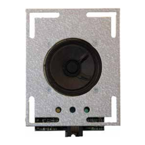
External Speaker & Microphone
Input: 12 - 24V DC
Relay 1 (N/O)
Speak
Use Pixel’s Emergency Lighting for a 12VDC emFONE output.
This provides additional battery backup time in the event of a power failure.
Built-in LED
Status Indicator
Idle
Calling (Line ON)
Speak (Call Answered)
OFFON
ONON
OFFOFF
Yellow Green
For improved noise immunity keep the speaker and microphone cables
short and away from high voltage wiring & DC & VF drives and audibly
noisy locaons, such as Eg. Li Cabin Ceiling Fans.
!
Power Supply
Relay Output Contacts
Alarm Button 2
Help Numbers Group 2
Alarm Button 1
Relay 2 (N/O)
Calling
Use Alarm Button 1 for single alarm button installs.
Acvaon: Press and HOLD to make an emergency call.
Buon HOLD Time: 3 seconds (Factory default)
Contact: Normally Open (N/O), Dry Contacts
For additional configurable ‘Alarm Button’ setting, please
refer to the Advanced Programming Guide.
!
Interface for External LED Pictograms
For additional configurable Relay settings, please
refer to the Advanced Programming Guide.
Some systems phone lines can provide a lower receive path
audio signal (dB).
The EM-1 can compensate by providing internal gain control. If you
find the audio level to be low at the speaker side, you can increase
the Line Receive Level (Rx Path). For programming details please refer
to the Advanced Programming Guide.
!
Ensure that they are flush mounted and inline with speaker grill and microphone
panel cutouts.
When mounng external speaker and microphone allow at least 80mm separaon
for opmal acousc and speakerphone performance.
EM-1/SM model comes with external Speaker & Microphone
Oponal external Speaker & Microphone kit P/N: EM-1-SPK/MIC
Idle
1 Second
Line / Power Fault
LED cutouts on back-side of enclosure
Speaker Microphone
SCAN ME
Help Numbers Group 1
