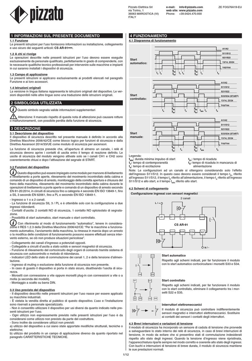
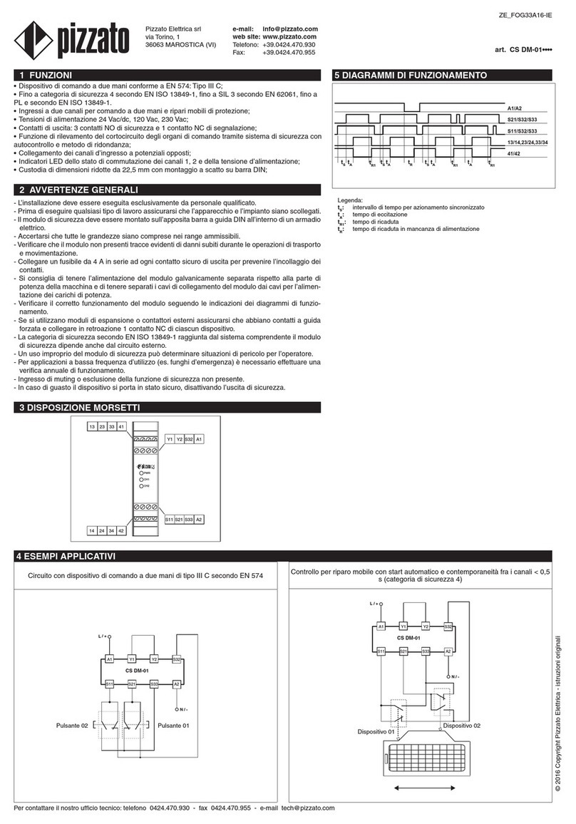
Pizzato Elettrica ST DD420MK User manual

1.4 FUNZIONAMENTO
Dopo esser stato correttamente installato seguendo le presenti istruzioni, il sensore
può esser alimentato. Lo schema sottostante rappresenta le 4 funzioni logiche che
interagiscono all’interno del sensore.
Nello stato iniziale di “POWER ON” la funzione f0 del sensore esegue un’autodiagnosi
interna che, se terminata con successo, porta il dispositivo nello stato “RUN”. Se il test
non è superato a causa di un guasto interno, il sensore entra nello stato di “ERROR”.
Lo stato “RUN” è di funzionamento normale: la funzione f1 valuta lo stato degli ingres-
si IS1, IS2 e contemporaneamente la funzione f2 verica la presenza dell’attuatore
nell’area di attivazione sicura.
Attenzione durante e dopo l’installazione:
• L’installazione deve essere eseguita esclusivamente da personale qualificato.
• Il sensore viene fornito abbinato univocamente all’attuatore presente nell’imballo.
• Alimentare il sensore e gli altri dispositivi di sicurezza ad esso connessi da un’unica
sorgente di tipo PELV o SELV con isolamento sicuro ed in conformità con le relative
norme.
• Si consiglia di alimentare il sensore di sicurezza utilizzando una sorgente separata
da quella del macchinario.
• Verificare che la tensione di alimentazione sia corretta prima di accendere il
dispositivo.
• Prima della messa in servizio e periodicamente verificare la corretta commutazione
delle uscite e il corretto funzionamento del sistema composto dal sensore e dal
modulo di sicurezza associato.
• Non utilizzare il sensore come arresto meccanico.
• Rispettare le distanze di intervento (sao) e di rilascio assicurate (sar).
• Si consiglia di effettuare le regolazioni mediante il diagramma riportato alla sezione
distanze di commutazione.
• Per le regolazioni non utilizzare un martello.
• Non montare il sensore e l’azionatore in forti campi magnetici.
• La categoria di sicurezza del sistema comprendente il sensore dipende anche dai
dispositivi esterni e dal loro collegamento.
• Per applicazioni a bassa frequenza di utilizzo è necessario effettuare una verifica
annuale di funzionamento.
Urti, vibrazioni e usura:
• Evitare collisioni con il sensore. Urti e vibrazioni eccessive potrebbero non garantire
un corretto funzionamento del sensore stesso.
•L’azionatore non deve urtare il sensore.
•In caso di danneggiamenti o di usura si deve sostituire il dispositivo completo, incluso
l’azionatore (nelle versioni non programmabili).
Attenzione durante il cablaggio:
•Mantenere il carico sotto il valore indicato nella categoria d’impiego.
• Togliere tensione prima di accedere alle connessioni del sensore.
• Scaricare l’elettricità statica prima di maneggiare il prodotto, toccando una massa
metallica connessa a terra. Scariche ESD potrebbero danneggiare il sensore.
• Collegare e scollegare il connettore M12 dal sensore solamente in assenza di
tensione.
I sensori utilizzano la tecnologia RFID per il controllo sicuro di protezioni e ripari
presenti nei macchinari industriali.
Tali sensori sono privi di contatti meccanici, quindi garantiscono una lunga durata di
funzionamento in sistemi soggetti a frequenti aperture/chiusure e operanti in condizioni
ambientali ostili.
Inoltre forniscono un elevato grado di protezione contro le manipolazioni, grazie
all’univocità del codice trasmesso dall’attuatore.
1 INTRODUZIONE
1.1 ATTENZIONE
•Il sensore può essere utilizzato come dispositivo di sicurezza (EN 60204) associato
ad un riparo mobile e al relativo modulo di sicurezza, secondo la normativa EN
60947-5-3 / A1.
•Il sensore può essere utilizzato come componente in un sistema di categoria di
sicurezza 4 / PLe secondo EN ISO 13849-1 e livello di integrità SIL CL 3 secondo
EN 62061.
•Utilizzare il dispositivo seguendo le istruzioni, attenendosi ai suoi limiti di funziona-
mento e impiegandolo secondo le norme di sicurezza vigenti.
•L’impiego conforme alla destinazione d’uso implica il rispetto delle vigenti norme
relative all’installazione e all’esercizio, in particolare: EN 60947-5-3 / A1, EN ISO
13849-1, EN 62061, EN 60204-1, EN 1088, EN ISO 12100-1, EN ISO 12100-2.
• La responsabilità del costruttore è esclusa in caso di:
- Impiego non conforme alla destinazione.
- Mancato rispetto delle istruzioni di sicurezza.
- Montaggio e riparazioni non eseguiti da persone specializzate e autorizzate.
- Omissione delle prove funzionali.
• Nei casi sotto elencati contattare il Supporto (punto 2):
- In centrali nucleari, treni, aeroplani, automobili, inceneritori, dispositivi medici o
comunque in applicazioni nelle quali la sicurezza di due o più persone dipenda dal
corretto funzionamento del dispositivo.
- Casi non citati nel foglio d’istruzioni.
1.2 LIMITI DI UTILIZZO
Stati del sensore:
OFF: il sensore è spento, non alimentato.
POWER ON: stato immediatamente successivo all’accensione nel quale il sensore
compie dei test interni.
RUN: stato nel quale il sensore è in funzionamento normale.
ERROR: stato di sicurezza nel quale le uscite vengono disattivate. Indica la presenza
di un guasto interno al sensore, un cortocircuito tra le uscite sicure (OS1, OS2), un
cortocircuito tra un’uscita sicura e massa oppure un cortocircuito tra un’uscita sicura
e la tensione di alimentazione. Per uscire da questo stato è necessario riavviare il
sensore.
PROGRAMMING: stato di programmazione nel quale le uscite sono disattive. Stato
previsto solo per le versioni programmabili.
1.3 DEFINIZIONI
Al vericarsi di queste due condizioni, la funzione f3 del sensore attiva le uscite sicure
OS1 e OS2. Gli ingressi del sensore ST sono monitorati oltre che per il loro stato,
anche per la loro coerenza: normalmente gli ingressi sono azionati in modo simulta-
neo. In caso di disattivazione di uno solo dei due ingressi, il sensore disattiva le uscite
sicure e segnala una condizione di non coerenza degli ingressi mediante il lampeggio
verde/arancio del LED IN. Entrambi gli ingressi devono essere disattivati, per poi es-
sere riattivati, afnché le uscite sicure possano essere nuovamente attive. Durante lo
stato di RUN, la funzione f0 esegue ciclicamente dei test interni al ne di evidenziare
eventuali guasti. Il rilevamento di un
qualsiasi errore interno porta il sen-
sore nello stato “ERROR” (LED PWR
rosso sso) che prevede la disattiva-
zione immediata delle uscite sicure.
Lo stato di “ERROR” può essere rag-
giunto anche nel caso si verichino
dei cortocircuiti tra le uscite sicure
(OS1, OS2) oppure il cortocircuito
di un’uscita verso massa o verso la
tensione di alimentazione. Anche in
questo caso la funzione f3 disattiva le
uscite sicure e lo stato di errore viene
segnalato dal lampeggio rosso del
LED OUT. L’uscita di segnalazione
O3 si attiva durante lo stato di “RUN”
in corrispondenza del rilevamento
dell’attuatore all’interno dell’area di
attivazione, indipendentemente dallo
stato degli ingressi IS1 e IS2. Lo sta-
to di questa uscita viene visualizzato
mediante il LED ACT.
Distanze di commutazione
Portando l’azionatore all’interno della zona sicura di azionamento (area grigio scuro),
il sensore abilita le uscite (LED OUT e LED ACT acceso verde).
All’uscita dell’azionatore dalla zona sicura, il sensore mantiene abilitate le uscite, ma
mediante il LED ACT (lampeggiante arancio/verde) segnala l’ingresso dell’azionatore
nella zona limite di azionamento (area grigio chiaro).
All’uscita dell’azionatore dalla zona limite di azionamento, il sensore disabilita le uscite
e spegne il LED OUT e il LED ACT.
ATTENZIONE!
Le distanze di attuazione/rilascio del dispositivo possono essere inuenzate dalla pre-
senza di materiale conduttivo o magnetico nelle vicinanze del sensore. Le distanze
utili di attuazione e rilascio devono sempre essere vericate dopo il montaggio.
25
20
15
10
5
0
25
20
15
10
5
0-15 -10 -5 0 5 10 15 -15 -10 -5 0 5 10 15
Legenda:
Distanza di attivazione sn (mm)
Distanza di sgancio snr (mm)
Nota: L’andamento delle aree di attivazione è indicativo.
Connessione in serie con moduli di sicurezza
E’ possibile installare più sensori connessi in cascata no ad un massimo di 32 unità,
mantenendo la categoria di sicurezza 4 / PLe secondo EN ISO 13849-1 e il livello di
integrità SIL CL 3 secondo EN 62061.
Vericare che il valore di PFH ed MTTFd del sistema costituito dalla cascata di sensori
e il modulo di sicurezza soddis ai requisiti del livello SIL/PL richiesto dall’applicazio-
ne.
Con questa modalità di collegamento si devono rispettare le seguenti avvertenze:
• Collegare gli ingressi del primo sensore della catena alla tensione di alimentazione.
• Le uscite dell’ultimo sensore della catena devono essere valutate da un modulo di
sicurezza.
• Utilizzare la cascata di sensori solo con i moduli di sicurezza indicati.
• Rispettare le distanze di posizionamento tra i sensori.
• Rispettare i limiti sulla capacità parassita delle linee d’uscita, indicati nelle caratteri-
stiche elettriche.
• Vericare che il tempo di risposta della cascata rispetti i requisiti della funzione di
sicurezza da realizzare.
• Il tempo di risposta della catena deve essere calcolato tenendo conto che il tempo di
risposta all’allontanamento dell’attuatore è diverso dal tempo di risposta alla disattiva-
zione degli ingressi. Se per esempio, osservando lo schema seguente, supponiamo
che sia il primo riparo della catena ad aprirsi, allora il tempo di risposta totale della
serie di sensori sarà al massimo: 150 ms + 12 ms + 12 ms = 174 ms.
ST D•••0MK
ST D•••0MK
ST D•••0MK
CS PLC
OS1 OS2
IS1 IS2
IS1 IS2
OS1 OS2
IS1 IS2
OS1 OS2
O3
SM D1T
SM D1T
SM D1T
O3
O3
+Vcc
f2
f1 f3
f0
OS1
OS2
IS2
IS1
IN
O3
PWR
A2A1
ACT
OUT
ZE_FOG84D12-IE
36063 MAROSTICA (VI)
Via Torino, 1
Telefono 0424.470.930
Fax 0424.470.955
e-mail [email protected]
www.pizzato.it
© 2012 Copyright Pizzato Elettrica - istruzioni originali

1.4 USE INSTRUCTIONS
After correct installation has been carried out following these instructions, the sensor
can be supplied with power supply.
The diagram below represents the four logic functions that interact within the sensor.
In the initial “POWER ON” state, the f0 function of the sensor carries out an internal
self-diagnosis which, if successfully completed, brings the device to the “RUN” state. If
the test is not passed due to an internal fault, the sensor enters the “ERROR” state.
The “RUN” state refers to normal operation: the function f1 evaluates the state of the
IS1 and IS2 inputs and simultaneously the f2 checks the presence of the actuator in
the safe activation area.
When these two conditions occur, the f3 function activates the OS1 and OS2 safety
outputs.
Warning during and after the installation:
• The installation must be performed by qualified staff only.
• The sensor is supplied as univocally combined with the actuator found in the
packing.
• The sensor and the other connected safety devices must be powered from a single
PELV or SELV type source having safe insulation and conforming to the relevant
standards.
• It is recommended to supply the safety sensor using a source separate from the
machinery source.
• Before switching on the device, check that the power supply is correct.
• Before installation and at regular intervals, check the right outputs switching and the
system operation of the sensor and the associated safety module.
• Do not use the sensor as a mechanical stop.
• Verify the assured operating (sao) and release distances (sar).
• It is advisable to make adjustment observing the diagram reported in the switching
distances section.
• Do not use a hammer to carry out adjustments.
• Do not install the sensor and the actuator on strong magnetic field.
• The safety category for the system including the sensor also depends on the external
devices and their connection.
• For applications using low working frequency, it is necessary to carry out an
operational test once a year.
Shock, vibrations and wear:
• Do avoid impact with the sensor. Excessive shock and vibrations could not guarantee
the right working of the sensor.
• The actuator must not strike sensor.
• In case of damages or wear is necessary to change the whole device, included the
actuator (for non programmable versions).
Warning during the wiring:
• Keep the load under the value given in the utilization category.
• Turn off the power supply before accessing the sensor connection contacts.
• Before handling the product, discharge any static electricity by touching a metallic
mass connected to earth. Electrostatic discharges (ESD) could damage the sensor.
• The M12 connector must only be connected and disconnected with the power supply
switched off.
The sensors use RFID technology for safe control of the guards present in industrial
machinery.
The said sensors have no mechanical contacts, therefore can guarantee long working
life for systems subject to frequent opening/closing manoeuvres and operating in
hostile environmental conditions.
Moreover, they provide a high level of protection against tampering, thanks to the
univocal code transmitted by the actuator.
1 INTRODUCTION
1.1 WARNING
• The sensor can be used as a safety device (EN 60204) associated with a mobile
guard and respective safety module, according to EN 60947-5-3 / A1 standards.
• The sensor can be used as a component in a safety category with 4 / PL e system
according to the EN ISO 13849-1 standard, and with SIL CL 3 integrity level accord-
ing to the EN 62061 standard.
• Use the device by following its instructions, observing its operation limits and using
it according to the safety standards in force.
• The utilization conformed to the final use, implies the respect of standards in force
regarding the installation and the operation, in detail: EN 60947-5-3 / A1, EN
13849-1, EN 62061, EN 60204-1, EN 1088, EN ISO 12100-1, EN ISO 12100-2.
• The manufacturer responsibility is excluded in case of:
- Utilization not according to final destination
- Not observing of the safety instructions
- Installation and reparations not performed by qualified and authorized staff.
- Omission of functional tests
• In following applications please beforehand contact Support (point 2)
- In nuclear power plants, trains, air crafts, cars, incinerators, medical devices or in
any applications where the safety of two or more persons depends on the right
operation of the device.
- Applications which are not contemplated in the instructions sheet.
1.2 UTILIZATION LIMITS
Sensor states:
OFF: the sensor is switched off, not powered.
POWER ON: state immediately following switching on, when the sensor carries out
internal tests.
RUN: state of the sensor in normal operation.
ERROR: safety state in which the outputs are deactivated. Indicates the presence of
a fault inside the sensor, a short circuit between the safety outputs (OS1 and OS2), a
short circuit between a safety output and the ground or a short circuit between a safety
output and the power supply. To come out of this state, it is necessary to restart the
sensor.
PROGRAMMING: programming state in which the outputs are deactivated. This state
is contemplated for programmable versions only.
1.3 DEFINITIONS
The sensor inputs are not only monitored for their state but also for their coherence:
the inputs are normally activated in a simultaneous way. In the case where only one
of the two inputs is deactivated, the sensor deactivates the safety outputs and signals
a non-coherent input condition by making the IN LED green/orange light blink. Both
inputs must be deactivated, and then reactivated for the safety inputs to become ac-
tive again.
During the RUN state, the f0 function carries out cyclical internal tests in order to show
up any fault. When any internal error
is detected, the sensor is brought to
the “ERROR” state (PWR LED with
red xed light) causing the safety out-
puts to be immediately deactivated.
The “ERROR” state can also be
reached in case of short circuits oc-
curring between the safety outputs
(OS1 and OS2) or a short circuit of
an output occurring towards ground
or towards supply voltage.
Also in this case, the f3 function de-
activates the safety outputs and the
error state is signalled by the OUT
LED red light blinking.
The O3 signalling output is activated
during the “RUN” state in correspond-
ence with the actuator being detected
within the activation area, independ-
ently from the IS1 and IS2 input state.
The state of this output is displayed
by the LED ACT.
Switching distances
When the actuator is brought inside the safe activation zone (dark grey area), the sen-
sor enables the outputs (LED OUT and LED ACT on, green).
When the actuator leaves the safe zone, the sensor keeps the outputs enabled; how-
ever, by means of the LED ACT (blinking, orange/green), it indicates that the actuator
is entering the limit activation zone (light grey area).
When the actuator leaves the limit activation zone, the sensor disables the outputs and
switches off the LED OUT and LED ACT.
WARNING!
Device’s actuation/release distances may be affected by the presence of conductive
or magnetic material close to the sensor. Actuation and release distances must be
veried after installation.
25
20
15
10
5
0
25
20
15
10
5
0-15 -10 -5 0 5 10 15 -15 -10 -5 0 5 10 15
Legend:
Activation distance sn (mm)
Deactivation distance snr (mm)
Note: The drawing of the activation areas is indicative.
Connecting with safety modules
It is possible for several sensors to be installed in cascade connection up to a maxi-
mum number of 32 units, while maintaining the safety category 4 / PL e according to
the EN ISO 13849-1 standard, and the SIL CL 3 integrity level according to the EN
62061 standard. Verify that the PFH and MTTFd value of the system, composed of
sensors chain and safety module, complies with the SIL/PL level requested by the
application.
With this connection method, the following instructions must be observed:
• Connect the inputs of the rst sensor in the chain to the power supply.
• The outputs of the last sensor in the chain must be evaluated by means of a safety
module.
• Use a sensor cascade only with the safety modules specied.
• Respect the positioning distances between the sensors.
• Respect the limits on the stray capacity of the output lines, specied in the electrical
characteristics.
• Check that the cascade response time respects the requirements of the safety func-
tion to be obtained.
• The chain response time must be calculated while keeping into account that the
response time following the actuator being moved away is different from the response
time following the inputs being deactivated. If for example, looking at the following
diagram, we assume that the rst guard of the chain is to open, then the total response
time of the ST series sensors will be at its maximum value: 150 ms + 12 ms + 12 ms
= 174 ms.
ST D•••0MK
ST D•••0MK
ST D•••0MK
CS PLC
OS1 OS2
IS1 IS2
IS1 IS2
OS1 OS2
IS1 IS2
OS1 OS2
O3
SM D1T
SM D1T
SM D1T
O3
O3
+Vcc
f2
f1 f3
f0
OS1
OS2
IS2
IS1
IN
O3
PWR
A2A1
ACT
OUT
© 2012 Copyright Pizzato Elettrica - original instructions
ZE_FOG84D12-IE
36063 MAROSTICA (VI) ITALY
Via Torino, 1
Phone +39.0424.470.930
Fax +39.0424.470.955
E-mail [email protected]
www.pizzato.com

Congurazione ingressi con start manuale (CS AR-05••••)
o start controllato (CS AR-06••••)
2 canali / Categoria 4 / no a SIL 3 / PL e
S21 S22 S34 A2
A1
-
+
S52
S12
OS2
OS1
IS2
IS1
A1
+
ST D•••••• A2
-
Collegamenti con i moduli di sicurezza CS AR-05•••• / CS AR-06••••
1.7 COLLEGAMENTO CON MODULI DI SICUREZZA
Collegamenti con i moduli di sicurezza CS AR-08••••
Congurazione ingressi con start controllato
2 canali / Categoria 4 / no a SIL 3 / PL e
S33
S21 S22 S35 S34 A2
S52
S12
A1
-
+
OS2
OS1
IS2
IS1
A1
+
A2
-
ST D••••••
Le connessioni variano in funzione del programma del modulo
Categoria 4/ no a SIL 3 / PL e
Ixx
Ixx
OS2
OS1
IS2
IS1
A1
+
ST D••••••
OS2
OS1
IS2
IS1
A1
+
ST D••••••
Ixx
Ixx
A2
-
A2
-
Collegamenti con i moduli di sicurezza CS MF••••0, CS MP••••0
Congurazione ingressi con start controllato
2 canali / Categoria 4 / no a SIL 3 / PL e
S33
S21 S22 S35 S34 A2
A1
-
+
S31
S12
OS2
OS1
IS2
IS1
A1
+
ST D•••••• A2
-
Collegamenti con i moduli di sicurezza CS AT-0••••• / CS AT-1•••••
La versione programmabile è dotata di un ingresso dedicato per poter programmare
il sensore afnchè riconosca il codice contenuto in un nuovo attuatore. Questa
operazione risulta ripetibile un numero illimitato di volte. A programmazione
avvenuta il sensore riconoscerà solo il codice dell’attuatore corrispondente all’ultima
programmazione effettuata.
Avvertenze
• Il costruttore della macchina deve permettere di accedere alla modalità di program-
mazione del sensore solamente al personale abilitato.
• Rispettare tutti i punti di avvertenza generale.
• Rispettare le avvertenze riportate nella sezione ISTRUZIONI DI MONTAGGIO E
COLLEGAMENTO.
• Ad operazione effettuata eseguire un controllo del riconoscimento del nuovo attua-
tore programmato e di funzionamento del sensore.
Procedura di programmazione
• Alimentare il sensore alla tensione nominale. Il sensore esegue dei test interni (1).
• L’operazione di programmazione è eseguibile sia con gli ingressi sicuri non attivi (2)
sia con gli ingressi sicuri attivi (3).
• Attivare l’ingresso di programmazione I3 portandolo alla tensione di 24 V. Il LED
IN inizia a lampeggiare con colore arancio ad indicare l’attesa del nuovo codice da
memorizzare (4).
• Appoggiare il nuovo attuatore al sensore allineando le tacche di riferimento con sim-
bolo . Il LED ACT a programmazione conclusa emette quattro lampeggii di colore
verde (5).
• La programmazione è andata a buon ne allo spegnimento del LED ACT (6). Disat-
tivare quindi l’ingresso di programmazione I3.
• Il sensore si riavvia automaticamente e riesegue dei test interni (7) per poi portarsi
nello stato di “RUN”.
PWR
LED OUT
LED IN
LED ACT
LED Stato
sensore Descrizione
arancio ///POWER ON
(1)
Test interni all’accensione
verde / / / RUN (2) Sensore in attesa degli
ingressi
verde /verde / RUN (3) Presenza degli ingressi, in
attesa dell’azionatore
verde /arancio
lampeg-
giante
/ PROGRAM-
MING (4)
Ingresso di
programmazione attivo, in
attesa del nuovo azionatore
da programmare
verde /arancio verde
lampeg-
giante
x 4
PROGRAM-
MING (5)
Ingresso di
programmazione attivo.
Memorizzazione del nuovo
codice avvenuta con
successo
verde /arancio / PROGRAM-
MING (6)
Ingresso di
programmazione attivo.
Programmazione terminata.
arancio ///POWER ON
(7)
Riavvio automatico e test
interni
Utilizzare i sensori di sicurezza ed azionatore in abbinamento con i moduli di sicurezza
indicati. Il sensore collegato al modulo di sicurezza può essere classicato come
dispositivo per circuito di comando no a PDF-M (EN 60947-5-3 / A1).
1.5 MODALITÀ DI PROGRAMMAZIONE
1.6 STATI DI FUNZIONAMENTO
PWR
LED OUT
LED IN
LED ACT
LED Stato
sensore Descrizione
////OFF Sensore spento.
arancio ///POWER
ON
Test interni all’accensione.
verde /RUN Sensore con gli ingressi non
attivi.
verde verde RUN Attivazione degli ingressi.
verde verde /
arancio
lampeg-
giante
RUN Non coerenza degli ingressi.
Azione consigliata: controllare
la presenza degli ingressi e/o il
loro cablaggio.
verde verde RUN Attuatore in area sicura.
Uscita di segnalazione O3 atti-
va.
verde verde /
arancio
lampeg-
giante
RUN Attuatore in zona limite, O3 at-
tiva.
Azione consigliata: riportare il
sensore all’interno dell’area si-
cura.
verde verde verde verde RUN Attivazione degli ingressi. At-
tuatore in area sicura e uscite
sicure attive.
verde rosso
lampeg-
giante
ERROR Errore sulle uscite.
Azione consigliata: verica-
re eventuali cortocircuiti tra le
uscite, uscite e massa o uscite
ed alimentazione e riavviare il
sensore.
rosso ERROR Errore interno.
Azione consigliata: riavviare il
sensore. Al persistere del gua-
sto sostituire il sensore.
/ = spento = indifferente
© 2012 Copyright Pizzato Elettrica - istruzioni originali

Inputs configuration with manual start (CS AR-05••••)
or monitored start (CS AR-06••••)
2 channels / Category 4 / up to SIL 3 / PL e
S21 S22 S34 A2
A1
-
+
S52
S12
OS2
OS1
IS2
IS1
A1
+
ST D•••••• A2
-
Connections with safety modules CS AR-05•••• / CS AR-06••••
1.7 CONNECTION WITH SAFETY MODULES
Connections with safety modules CS AR-08••••
Inputs configuration with monitored start
2 channels / Category 4 / up to SIL 3 / PL e
S33
S21 S22 S35 S34 A2
S52
S12
A1
-
+
OS2
OS1
IS2
IS1
A1
+
A2
-
ST D••••••
Connections change depending on the program running on the module
Category 4 / up to SIL 3 / PL e
Ixx
Ixx
OS2
OS1
IS2
IS1
A1
+
ST D••••••
OS2
OS1
IS2
IS1
A1
+
ST D••••••
Ixx
Ixx
A2
-
A2
-
Connections with safety modules CS MF••••0, CS MP••••0
Inputs configuration with monitored start
2 channels / Category 4 / up to SIL 3 / PL e
S33
S21 S22 S35 S34 A2
A1
-
+
S31
S12
OS2
OS1
IS2
IS1
A1
+
ST D•••••• A2
-
Connections with safety modules CS AT-0••••• / CS AT-1•••••
The sensor is provided with a dedicated input, which enables programming of the
sensor in order to recognise the code contained in a new actuator. This operation
can be repeated for an unlimited number of times. After programming has been
completed, the sensor will only recognise the actuator code corresponding to the last
programming operation.
Warnings
• The machine manufacturer must allow qualied personnel only to access the sensor
programming mode.
• Observe all general directions.
• Observe all directions contained in the section for INSTALLATION AND CONNEC-
TION INSTRUCTIONS.
• After completing the operation, check for new programmed actuator recognition and
for sensor operation.
Programming procedure
• Supply the sensor with the rated voltage. The sensor carries out internal tests (1).
• The programming operation can be carried out with non-active safety inputs (2) as
well as with active safety inputs (3).
• Activate the I3 programming input by bringing it to a 24 V voltage. The IN LED starts
blinking with an orange light to indicate that it is waiting for the new code to be
memorized (4).
• Put the new actuator against the sensor, aligning the reference notches with the
symbol . After programming has been completed, the ACT LED emits four green
blinks (5).
• When the ACT LED (6) switches off, it means that the programming operation has
been successful. At this point deactivate the I3 programming input.
• The sensor automatically reactivates and power on self-tests (7) before being brought
to the “RUN” state.
PWR
LED OUT
LED IN
LED ACT
LED Sensor
state Description
orange ///POWER ON
(1)
Internal tests on activation
green / / / RUN (2) Sensor waiting for inputs
green /green / RUN (3) Presence of inputs, waiting
for the actuator
green /orange
blink-
ing
/ PROGRAM-
MING (4)
Programming input active,
waiting for the new actuator to
be programmed
green /orange green
blink-
ing x 4
PROGRAM-
MING (5)
Programming input active.
New code memorization
successfully completed
green /orange / PROGRAM-
MING (6)
Programming input active.
Programming completed
orange ///POWER ON
(7)
Automatic restart and internal
tests
Use safety sensor with the actuator linking together with Pizzato Elettrica safety
modules. The sensor connected to the safety module could be classied as control
circuit device up to PDF-M (EN 60947-5-3 / A1).
1.5 PROGRAMMING MODE
1.6 OPERATIONAL STATES
PWR
LED OUT
LED IN
LED ACT
LED Sensor
state Description
////OFF Sensor off.
orange ///POWER
ON
Internal tests on activation.
green /RUN Sensor inputs not active.
green green RUN Inputs activation.
green
green /
orange
blinking RUN
Inputs inconsistency.
Recommended action: check
the inputs and / or their wiring.
green green RUN Actuator in the safe activation zone
Auxiliary output O3 active.
green
green /
orange
blinking RUN
Actuator in the limit activation
zone. Recommended action:
bring the sensor within the safe
activation zone.
green green green green RUN Inputs activation. Actuator in the
safe activation zone and safety
outputs active.
green
red
blinking ERROR
Outputs error.
Recommended action: check for
short circuits between outputs,
outputs and ground, or outputs
and power supply; restart the
sensor.
red ERROR Internal error.
Recommended action: restart
the sensor. If the fault persists,
replace the sensor.
/ = off = indifferent
© 2012 Copyright Pizzato Elettrica - original instructions

Caratteristiche meccaniche
Grado di protezione:
Tipo di connettore:
Materiale:
Grado d’inquinamento:
Resistenza agli urti:
Resistenza alle vibrazioni:
Temperatura di esercizio:
Temperatura di immagazzinamento e
trasporto:
Coppia di serraggio viti:
Lunghezza massima dei cavi di collegamento:
IP67 e IP69K
M12 – 8 poli
Poliammide PA66
3
30 gn; 11 ms secondo EN 60068-2-27
10 gn; (10…55 Hz) EN 60068-2-6
-25…+70 °C
-25…+85 °C
0,8 ... 2 Nm
50 m (la lunghezza del cavo e la sua sezione
alterano gli impulsi di disattivazione sulle uscite
sicure. Vericare che la capacità tra i conduttori
del cavo di collegamento sia inferiore a quella
ammessa nelle caratteristiche elettriche delle
uscite sicure)
Caratteristiche elettriche
Tensione nominale d’impiego Ue:
Corrente nominale d’impiego Ie:
Corrente termica Ith:
Corrente minima d’impiego:
Carico massimo commutabile:
Assorbimento alla tensione Ue:
Tensione nominale di isolamento Ui:
Tensione di tenuta ad impulso nominale Uimp:
Fusibile di protezione interno
ripristinabile(OS1+OS2+O3):
Fusibile di protezione esterno:
Categoria di sovratensione:
24 Vdc -15%...+10%
0,25 A
0,25 A
0,5 mA
6 W
< 1W
32 V
1,5 kV
0,75 A
1 A
III
1.9 CARATTERISTICHE TECNICHE
2.1 STRUTTURA CODICE
1.8 ISTRUZIONI DI MONTAGGIO E COLLEGAMENTO
Direzioni d’azionamento
Le tacche centrali di riferimento del sensore e dell’azionatore
devono essere contrapposte.
• Fissare le viti con una coppia di serraggio di 0,8 ... 2 Nm.
• Fissare il sensore e l’azionatore in modo irremovibile al
dispositivo di sicurezza (viti antisvitamento, rivetti, ecc).
• Fissare il sensore soltanto su superci piane, per evitare
possibili distorsioni che potrebbero lesionare il sensore
oppure alterare le distanze di commutazione.
• I sensori e gli azionatori vengono forniti con appositi tappi
per la copertura delle asole di alloggiamento delle viti di
fissaggio.
ST D•3••MK con connettore
M12 (8 pin)
ST D•4••MK con connettore
M12 (8 pin)
1
2
345
6
7
8
pin
1 A1
2 IS1
3 A2
4 OS1
5 O3
6 IS2
7 OS2
8 non
connesso
1
2
345
6
7
8
pin
1 A1
2 IS1
3 A2
4 OS1
5 O3
6 IS2
7 OS2
8 I3
Legenda
A1-A2 alimentazione
IS1-IS2 ingressi sicuri
OS1-OS2 uscite sicure
O3 uscita di
segnalazione
I3 ingresso di
programmazione
Collegamenti interni connettore
Dimensioni d’ingombro
12.512.5
33
279 9
45
25
4.2
9.2
18
3 3
27 99
9.2
7.2
4.2
60
4.3
M12
72 15.5
3 5.6
18
8.5
6.8
25
7215.5
60
3 5.6
4.3
M12
18
8.5
6.8
25
Sensore ST DD•••MK
con connettore M12
a destra
Sensore ST DL•••MK
con connettore M12 a
sinistra
Azionatore SM D•T
ST DD310MK-D1T
Verso di uscita connessioni
Duscita a destra
Luscita a sinistra
Ingressi e uscite
uscite
sicure
OS
uscite di
segnalazi-
one O
ingressi
sicuri IS
ingressi di
program-
mazione I
32 1 2 -
42 1 2 1
Tipo di cavo integrato o connettore
MK connettore M12 a 8 poli
Programmazione
1codice univoco e sso
2programmabile (solo articolo
ST D•420MK)
Montaggio di più sistemi sensore-azionatore
La distanza minima di montaggio fra sistemi
sensore-azionatore deve essere almeno di
50 mm, in tutte le direzioni.
50
Fissaggio del sensore e dell’azionatore
2 SUPPORTO
Per informazioni e supporto contattare l’ufcio tecnico: telefono 0424.470.930 - fax
0424.470.955 - e-mail [email protected]
Caratteristiche elettriche ingressi IS1/IS2/I3
Tensione nominale d’impiego Ue1:
Corrente nominale assorbita:
24 Vdc
5 mA
Caratteristiche elettriche uscite sicure OS1/OS2
Tensione nominale d’impiego Ue1:
Tipo di uscita:
Corrente massima per uscita Ie1:
Categoria d’impiego:
Rilevamento cortocircuiti:
Protezione contro sovracorrenti:
Durata degli impulsi di disattivazione sulle
uscite sicure:
Capacità ammessa tra uscita e uscita:
Capacità ammessa tra uscita e massa:
24 Vdc
PNP
0,25 A
DC12; Ue=24 Vdc, Ie=0,25 A
Sì
Sì
< 300 us
< 200 nF
< 200 nF
Caratteristiche elettriche uscita di segnalazione O3
Tensione nominale d’impiego Ue1:
Tipo di uscita:
Corrente massima per uscita Ie1:
Rilevamento cortocircuiti:
Protezione contro sovracorrenti:
24 Vdc
PNP
0,1 A
No
Sì
Caratteristiche d’azionamento
Distanza d’intervento assicurata sao:
Distanza di rilascio assicurata sar:
Distanza d’intervento nominale sn:
Distanza di rilascio nominale snr:
Precisione della ripetibilità:
Corsa differenziale:
Frequenza massima di commutazione:
Distanza tra due sensori:
Tempo di risposta alla disattivazione degli
ingressi:
Tipico:
Massimo:
Tempo di risposta all’allontanamento
dell’attuatore:
Tipico:
Massimo:
10 mm
16 mm
12 mm
14 mm
≤ 10 % sn
≤ 20 % sn
1 Hz
min. 50 mm
7 ms
12 ms
80 ms
150 ms
Altre caratteristiche
Conformità agli standard:
Conformità alle direttive:
FCC Part 15 Statements:
Omologazione TUV SUD:
Omologazione UL:
Omologazione GOST:
Livello SIL (SIL CL):
Performance Level (PL):
Categoria di sicurezza:
PFHd:
MTTFd (single channel):
DC:
Tempo di vita/Mission time:
Classicazione:
IEC 61508-1, IEC 61508-2, IEC 61508-3, IEC
61508-4, EN 954-1, SN 29500, EN ISO 13849-
1, EN ISO 13849-2, EN 62061, EN 60947-5-3 /
A1, EN 60947-5-2, EN 60947-1, EN 61326-1, EN
61326-3-1, EN 61326-3-2, ETSI 301 489-1, ETSI
301 489-3, ETSI 300 330-2
2006/95/CE, 2006/42/CE, 2004/108/CE,
1995/05/CE
This device complies with part 15 of the FCC
Rules. Operation is subject to the following two
conditions: (1) This device may not cause harmful
interference, and (2) this device must accept any
interference received, including interference that
may cause undesired operation.
Z10 12 11 75157 004
E131787
POCC IT.AB24.B04512
no a SIL 3 secondo EN 62061:2005
no a PL e secondo EN ISO 13849-1: 2008
no a 4 secondo EN ISO 13849-1: 2008
1,20E-11
4077 anni
High
20 anni
PDF-M
1.10 SMALTIMENTO
2.2 DICHIARAZIONE CE DI CONFORMITÀ
Azionatore
D0T completo di azionatore SM D0T
distanza di azionamento 12 mm
D1T completo di azionatore SM D1T
distanza di azionamento 12 mm
© 2012 Copyright Pizzato Elettrica - istruzioni originali
Il prodotto deve essere smaltito correttamente a ne vita
Il sottoscritto, rappresentante il seguente costruttore :
Pizzato Elettrica s.r.l. , Via Torino, 1 - 36063 Marostica (VI) - Italy
dichiara qui di seguito che il prodotto risulta in conformità con quanto previsto dalla
Direttiva macchine 2006/42/CE. La versione completa della dichiarazione di conformi-
tà è disponibile su sito www.pizzato.com
Ing. Pizzato Giuseppe
Disclaimer:
Con riserva di modifiche senza preavviso e salvo errori. I dati riportati in questo foglio sono
accuratamente controllati e rappresentano tipici valori della produzione in serie. Le descrizioni del
dispositivo e le sue applicazioni, i contesti di impiego, i dettagli su controlli esterni, le informazioni
sull’installazione e il funzionamento sono forniti al meglio delle nostre conoscenze. Ad ogni modo ciò
non signica che dalle caratteristiche descritte possano derivare responsabilità legali che si estendano
oltre le “ Condizioni Generali di Vendita” come dichiarato nel catalogo generale di Pizzato Elettrica. Il
cliente/utente non è assolto dall’obbligo di esaminare le nostre informazioni e raccomandazioni e le
normative tecniche pertinenti prima di usare i prodotti per i propri scopi.

© 2012 Copyright Pizzato Elettrica - original instructions
Mechanical data
Protection degree:
Type of connector:
Material
Pollution degree:
Shock resistance:
Vibrations resistance:
Operating temperature:
Storage and transport temperature:
Max screws tightening torque:
Maximum connection cable length:
IP67 and IP69K
M12 – 8 poles
Polyamide PA66
3
30 gn; 11 ms according to EN 60068-2-27
10 gn; (10…55 Hz) EN 60068-2-6
-25…+70 °C
-25…+85 °C
0,8 ... 2 Nm
50 m (the cable length and cross section alter
deactivation impulses on safety outputs. Check
that the capacity between connection cable
leads is lower that the one admitted in the electri-
cal characteristics for safety outputs)
Electrical data
Rated operational voltage Ue:
Rated operational current Ie:
Thermal current Ith:
Rated minimum current:
Max switching load:
Power consumption (Ue):
Rated insulation voltage Ui:
Rated impulse withstand voltage Uimp:
Internal restorable protection fuse
(OS1+OS2+O3):
Protection fuse:
Over-voltage category:
24 Vdc -15%...+10%
0,25 A
0,25 A
0,5 mA
6 W
< 1W
32 V
1,5 kV
0,75 A
1 A
III
2.1 CODE STRUCTURE
1.8 INSTALLATION AND CONNECTION INSTRUCTIONS
Functional directions
The sensor and actuator central reference marks must be
opposed.
Sensor and actuator xing
ST D•3••MK with M12
connector (8 pin)
ST D•4••MK with M12
connector (8 pin)
1
2
345
6
7
8
pin
1 A1
2 IS1
3 A2
4 OS1
5 O3
6 IS2
7 OS2
8 not
connected
1
2
345
6
7
8
pin
1 A1
2 IS1
3 A2
4 OS1
5 O3
6 IS2
7 OS2
8 I3
Legend
A1-A2 power supply
IS1-IS2 safety inputs
OS1-OS2 safety outputs
O3 auxiliary output
I3 programming
input
Internal connector connections
Overall dimensions
12.512.5
33
279 9
45
25
4.2
9.2
18
3 3
27 99
9.2
7.2
4.2
60
4.3
M12
72 15.5
3 5.6
18
8.5
6.8
25
7215.5
60
3 5.6
4.3
M12
18
8.5
6.8
25
Sensor ST DD•••MK
with M12 connector on
the right
Sensor ST DL•••MK
with M12 connector on
the left
Actuator SM D•T
ST DD310MK-D1T
Connection output direction
Doutput from right
Loutput from left
Inputs and outputs
safety
outputs
OS
auxiliary
outputs
O
safety
inputs
IS
program-
ming
inputs
I
32 1 2 -
42 1 2 1
Type of cable or connector
MK 8 poles M12 connector
Programming
1unique xed code
2programmable (only article
ST D•420MK)
Multiple systems sensor-actuator assembly
The minimum mounting gap between sensor-
actuator systems must be at least 50 mm, in
any directions.
50
1.9 TECHNICAL DATA
• Fasten the screws with a max tightening torque of 0.8 … 2 Nm
• Fasten steadfastly the sensor and the actuator to the safety
device (by means of rivets, tamper-proof screws, etc.).
• Fasten the sensor on plane surface only, in order to avoid
possible distortions that could damage the sensor or alter
switching distances.
• Sensors and actuators are supplied with appropriate caps for
covering the slots housing the fixing screws
2 SUPPORT
For further information and support please contact the technical departement: ph.
0039.0424.470.930 - fax 0039.0424.470.955 - e-mail [email protected]
1.10 DISPOSAL
At the end of service life product must be disposed of properly
Input circuits IS1/IS2/I3
Rated operational voltage Ue1:
Absorbed rated current:
24 Vdc
5 mA
Safety output circuits OS1/OS2
Rated operational voltage Ue1:
Signal type:
Max current for output Ie1:
Utilization category:
Short circuits detection:
Protection against short circuits:
Time for deactivation impulses on safety
outputs:
Capacity admitted between one output and
the next:
Capacity admitted between output and ground:
24 Vdc
PNP
0,25 A
DC12; Ue=24 Vdc, Ie=0,25 A
yes
yes
< 300 us
< 200 nF
< 200 nF
Output circuit O3
Rated operational voltage Ue1:
Signal type:
Max current for output Ie1:
Short circuits detection:
Protection against short circuits:
24 Vdc
PNP
0,1 A
No
yes
Actuating data
Assured operating distance sao:
Assured release distance sar:
Rated operating distance sn:
Rated release distance snr:
Repeat accuracy:
Differential travel:
Maximum frequency of operating cycles:
Distance between two sensors:
Response time after input deactivation:
Standard:
Maximum:
Response time after actuator removal:
Standard:
Maximum:
10 mm
16 mm
12 mm
14 mm
≤ 10 % sn
≤ 20 % sn
1 Hz
min. 50 mm
7 ms
12 ms
80 ms
150 ms
Others data
Conforms to the standards:
Conforms to the directives:
FCC Part 15 Statements:
Approvals TUV SUD:
Approvals UL:
Approvals GOST:
SIL level (SIL CL):
Performance Level (PL):
Safety category:
PFHd:
MTTFd (single channel):
DC:
Mission time:
Classication:
IEC 61508-1, IEC 61508-2, IEC 61508-3, IEC
61508-4, EN 954-1, SN 29500, EN ISO 13849-
1, EN ISO 13849-2, EN 62061, EN 60947-5-3 /
A1, EN 60947-5-2, EN 60947-1, EN 61326-1, EN
61326-3-1, EN 61326-3-2, ETSI 301 489-1, ETSI
301 489-3, ETSI 300 330-2
2006/95/EC, 2006/42/EC, 2004/108/EC,
1995/05/EC
This device complies with part 15 of the FCC
Rules. Operation is subject to the following two
conditions: (1) This device may not cause harmful
interference, and (2) this device must accept any
interference received, including interference that
may cause undesired operation.
Z10 12 11 75157 004
E131787
POCC IT.AB24.B04512
up to SIL 3 according to EN 62061:2005
up to PL e according to EN ISO 13849-1: 2008
up to category 4 according to EN ISO 13849-1: 2008
1,20E-11
4077 years
High
20 years
PDF-M
2.2 EC DECLARATION OF CONFORMITY
Actuator
D0T complete with SM D0T actuator
actuation distance 12 mm
D1T complete with SM D1T actuator
actuation distance 12 mm
Disclaimer:
Technical modications and errors reserved. The data quoted in this sheet are carefully checked and
represent typical series values.
Descriptions of device and its applications, the control contexts, details on external controls, installation
and operating information are given to the best of our knowledge. This does not mean however that
any assured properties or other claims under liability law that extend beyond the “General Sales
Terms” as stated in the Pizzato Elettrica general catalogue may be derived. The user is not absolved
of his obligation to examine our information and recommendations before using them for his own
purposes.
The undersigned, representing the following manufacturer:
Pizzato Elettrica s.r.l. , Via Torino, 1 - 36063 Marostica (VI) - Italy
herewith declares that the product is in conformity with the Machinery directive
2006/42/CE. The complete EC Declaration of Conformity is available on
www.pizzato.com
Ing. Pizzato Giuseppe
This manual suits for next models
3
Table of contents
Other Pizzato Elettrica Safety Equipment manuals
Popular Safety Equipment manuals by other brands

hager
hager EE960 quick start guide

Honeywell
Honeywell ESSIAN 2 Instructions for use

Petzl
Petzl RAY 11 mm manual

Innotech
Innotech SDH-32 Safety instructions and instruction manual

babcockdavis
babcockdavis Safe-T-Lume BEM-DS1 Installation, operation and maintenance manual

Climbing Technology
Climbing Technology ROLLNLOCK 2D652 manual