Planar LookThru User manual

Planar®LookThru™ Transparent OLED Display
Fabricator’s Guide

2 Planar LookThru Fabricator’s Guide 020-1315-00C
Table of Contents
Table of Contents............................................................................................................................2
What’s in the Box............................................................................................................................3
Display.........................................................................................................................................3
Counterweight Plate....................................................................................................................3
Cable Cover.................................................................................................................................3
HDMI and Power Cables.............................................................................................................3
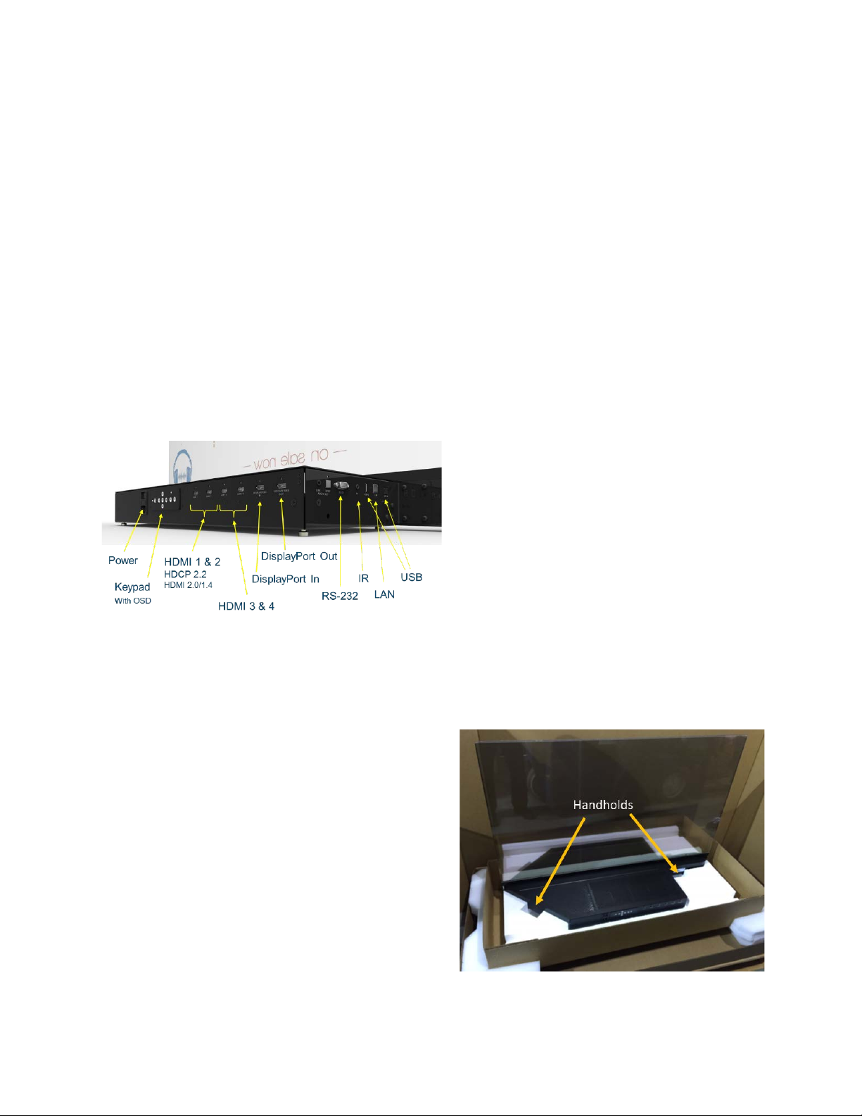
External Connections..................................................................................................................4
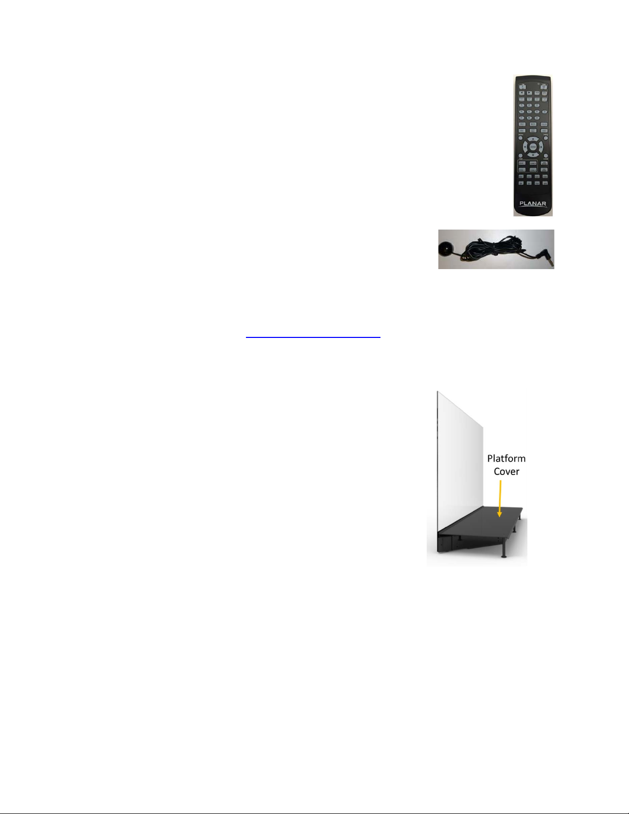
Remote and Sensor....................................................................................................................4
Quick Start Guide........................................................................................................................4
Optional Accessories......................................................................................................................4
Platform Cover: 955-0595-xx......................................................................................................4
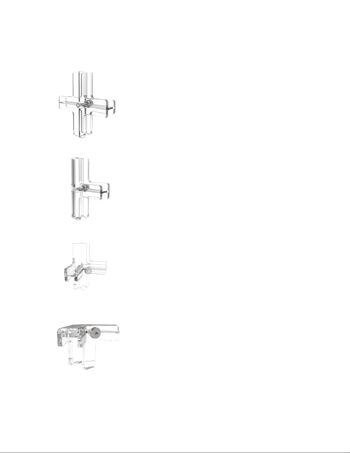
Tiling Kit.......................................................................................................................................4
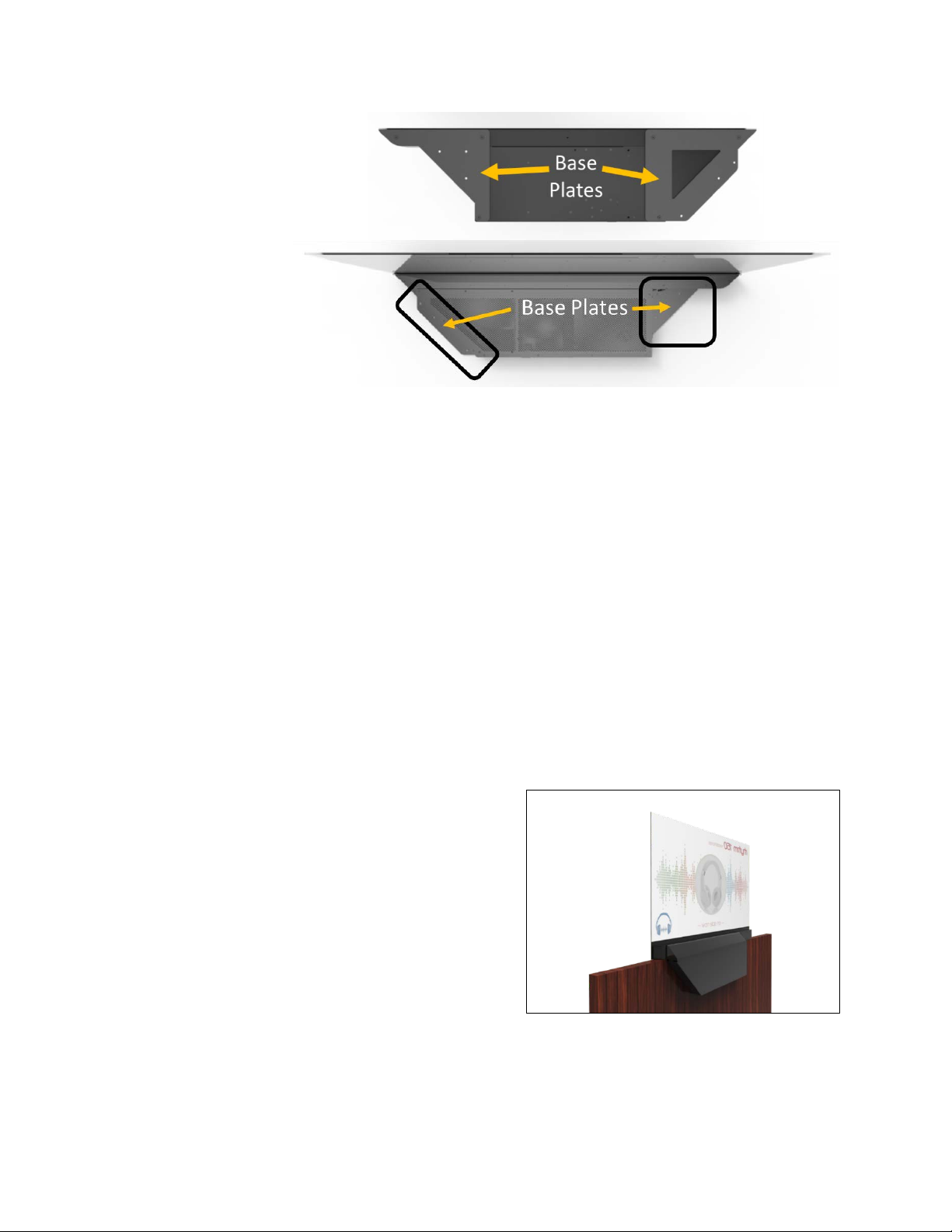
Base Plate Kit: 935-0425-xx .......................................................................................................7
Introduction to the Planar LookThru Display..................................................................................7
Short Description of OLED Technology and Planar LookThru Design...................................... 7
Safe Handling..............................................................................................................................8
Cleaning ......................................................................................................................................9
Environmental Considerations..................................................................................................10
How To Use Planar LookThru Display.........................................................................................10
General Instructions..................................................................................................................11
Mechanical Considerations...........................................................................................................11
Electrical....................................................................................................................................11
Thermal .....................................................................................................................................11
Tabletop Installation..................................................................................................................12
Mounting....................................................................................................................................12
Optical Considerations..................................................................................................................14
Luminance.................................................................................................................................14
Transparency.............................................................................................................................14
Sunlight......................................................................................................................................15
User-Provided Touch....................................................................................................................15
Content..........................................................................................................................................15
Safety Considerations...................................................................................................................15
Structural...................................................................................................................................15
Glass..........................................................................................................................................16
Thermal .....................................................................................................................................16
Specifications................................................................................................................................17
Line Drawings ...............................................................................................................................17
Regulatory Information .................................................................................................................17

3 Planar LookThru Fabricator’s Guide 020-1315-00C
The purpose of this document is to provide guidelines and help for installers and fabricators
working with the Planar®LookThru™ Transparent OLED Display. This document does not
replace the User Manual or the Content Developer’s Guide. It does not provide specifics on how
to work in each environment where a Planar LookThru display may be installed. This document
is intended to provide expert fabricators and installers with the information and understanding
necessary to make the most of the Planar LookThru display.
Detailed specification and instructions on operating the Planar LookThru display are found in the
User Manual located at www.planar.com/LookThru.
What’s in the Box
Display
Planar LookThru displays come in two models (described
in detail in the next section) and both models have three
main components: Display Glass, Display Chassis and
Electronics Box. The Display Chassis is the main support
for the entire display and should be used when removing
the display from the box, moving it or mounting it during
installation.
Counterweight Plate
The Counterweight Plate serves as a stabilizer and ships
attached to the Electronics Box on Standard Models
(more information on models later). The Counterweight
Plate should be removed if the Planar LookThru display
will be mounted to a fixture or surface.
Cable Cover
Due to the orientation of the circuit boards in the Electronics Box, it is
asymmetrical when compared to the Display Chassis. The Cable
Cover makes the Electronics Box symmetrical without restricting
access to the I/O ports.
Note: Never use the Cable Cover to lift or move the display
HDMI and Power Cables
The Planar LookThru display ships with a 110VAC power cable with
C14 connector and one HDMI cable. The display has four HDMI
ports (2x 2.0 and 2x 1.4), one DisplayPort input (1.2), one
DisplayPort output, as well as connections for RS-232 controllers, LAN, USB and the infrared
sensor.
Standard Model

4 Planar LookThru Fabricator’s Guide 020-1315-00C
External Connections
The Planar LookThru display has four HDMI ports (2x 2.0 and 2x
1.4), one DisplayPort input (1.2), one DisplayPort output, as well as
connections for RS-232 controllers, LAN, USB and the infrared
sensor.
Remote and Sensor
The Planar LookThru display is controlled by the included Remote
Control through an On-Screen Display (OSD). To increase the range
of the Remote Control, a 112-inch (2850mm) Remote IR sensor is
also included.
Quick Start Guide
A printed guide with the basic information necessary to start and operate the Planar LookThru
display is included, but the more detailed User Manual, Content Developer’s Guide and this
Fabrication Guide are available at www.planar.com/LookThru.
Optional Accessories
Depending on your installation needs, the optional accessories may
help to facilitate proper use of a Planar LookThru display.
Platform Cover: 955-0595-xx
The Electronics Box has perforations that allow for proper airflow
and cooling. If the installation requires items to be placed close to
the Display Glass, the platform cover protects the Electronics Box
and supports any display items. The Platform Cover can
accommodate display items up to a total of 20 lbs. (9kg). Do not
exceed 20 lbs. in total weight on the Platform Cover.
Tiling Kit
If multiple Planar LookThru displays will be tiled, optional tiling hardware can be used to help
connect the free corners of the Display Glass (i.e. not the corners connected to the Display
Chassis).
Note that the Display Glass is not designed to bear any load. The tiling hardware only connects
the corners of the Display Glass and does not provide any structural support for the displays or
any fabricated installation.
Remote Control and IR Sensor

5 Planar LookThru Fabricator’s Guide 020-1315-00C
Here are the four tiling components:
oPlus sign shape for flat (2x2): 935-0421-XX
oT-shape for flat (2x1): 935-0422-XX
oPlus sign shape for angle (2x2) : 935-0423-XX
oT-shape for right angle (2x1): 935-0424-XX
Plus sign shape for angle 2x2 (left) and T-shape for angle 2x1 (right)

6 Planar LookThru Fabricator’s Guide 020-1315-00C
Below are examples of how to use the tiling hardware to connect the Planar LookThru displays.
Sample installation using the tiling hardware.

7 Planar LookThru Fabricator’s Guide 020-1315-00C
Base Plate Kit:
935-0425-xx
If the display will be
mounted to a ceiling,
wall or table top, the
Base Plate Kit
provides a mounting
platform. The Base
Plate aligns with the
mounting holes on
the standard version of the Planar LookThru display (more about the version in the next section)
and allows the mounting into the support structure to be independent of the mounting points on
the Display Chassis and Electronics Box. The Base Plate can be used for either landscape or
portrait orientation and is designed to accommodate standard wall studs that are 16 inches on
center. The Base Plates provide adequate airflow for the Planar LookThru display and allow
multiple displays to be connected and mounted together.
Introduction to the Planar LookThru Display
The Planar LookThru display represents a new type of display technology. With that newness
comes some considerations that must be addressed.
Short Description of OLED Technology and Planar LookThru Design
The Planar LookThru display uses active-matrix organic light-emitting diodes to create an
emissive display that is also transparent (technically translucent with 38% of light passing
through it). Because each pixel is made up of light-emitting diodes, there is no backlight as on a
traditional LCD display; rather, each pixel generates its own light and heat.
The Planar LookThru display comes in two models:
-LO552: Standard Model
-LO552-S: Straight Mount Model
-
The Standard Model has the Electronics Box set at
a 90-degree angle to the Display Glass. The
Straight Mount Model has the Electronics Box set
parallel to and below the Display Glass for
installations.
Front vs Rear Viewing
Because each pixel is emitting its own light, the
display can be viewed from the back as well as the front (the back side being where the
Straight Mount Model (LO552-S)

8 Planar LookThru Fabricator’s Guide 020-1315-00C
Electronics Box is located). However, the light emitted toward the rear is significantly less –
approximately 90% - than that on the front, and any image viewed from behind will be reversed.
Cooling Features
The Planar LookThru display generates significant heat that must be dissipated. The Electronics
Box is perforated to allow for proper airflow but installations must keep at least 0.25 inches
(5mm) between the Electronics Box and the mounting surface and 0.5 inches (12mm) above the
Electronics Box to allow for that airflow. Additionally, dust build-up can prevent adequate cooling
so regular vacuuming must be facilitated in the installation to allow for the cooling features to
work.
Glass Treatment
The front surface of the Display Glass is made of Corning®Gorilla®Glass, and is coated with an
anti-reflective coating that is optically bonded to the OLED display. The Corning Gorilla Glass
provides scratch resistance on the front of the display only. The back side of the display is
susceptible to damage from sharp and/or hard objects and should be protected accordingly.
Input/Output
A single display installation can be driven
from any HDMI or DisplayPort capable
source. If multiple displays will be tiled
together, the RS-232 connection will allow
custom display hardware to drive the
displays.
Installations should take into account the
location of the inputs on the Electronics Box, as well as provide access to either the keypad on
the back or the Remote Control (with an included 112inch extension cord and sensor).
Safe Handling
When removing the display from its box or moving
it around, hold it by the indicated handholds on
the Display Chassis and Electronics Box. Do not
lift, move or shift the display by the Display Glass.
It is recommended to have at least two people
when moving or installing the display.
The display ships with a protective film over both
the front and rear sides of the Display Glass.
When removing the film there is a possibility of
electrostatic discharge (ESD). Wear an
appropriate ESD safety device and/or connect the
Planar LookThru display’s power cord to a

9 Planar LookThru Fabricator’s Guide 020-1315-00C
grounded outlet before removing the protective
film to prevent ESD damage to the electronic
components.
Do not bend or flex the Display Glass away from
the Display Chassis. The glass is not designed to
bear any weight or to be flexed at all. Doing so
can weaken the connections between the Display
Glass and the Display Chassis and result in
damage to the display.
It is recommended that the shipping box be used
whenever transporting a Planar LookThru display.
Retain the shipping box if you think the display
may be transported after initial installation.
The Electronics Box needs at least 0.25 inches (5mm) below and 0.5 inches (12mm) above of
clearance for adequate airflow. Carpet or other soft materials that can flex by at least 0.25
inches are not suitable installation bases for the display.
If the feet need to be removed from the Display Chassis and Electronics Box for a mounted
installation, at least two people should lay the Display Glass flat on a protected surface so that
the Electronics Box is in the air (ideally before the protective film is removed). Remove the feet
and then, lifting by the Electronics Box and Display Chassis, return the Planar LookThru display
to a vertical position.
Cleaning
Appropriate cleaning will be necessary both after installation and throughout the life of the
display.
Metal Surfaces
Wipe the metal surfaces of the Display Chassis and the Electronics Box with a dry, lint-free
towel. If any cleaning product is necessary, it should be applied sparingly to the towel and never
directly to the display. No liquid should be allowed to get into the Electronics Box or into the gap
between the Display Glass and chassis.
Use a vacuum cleaner to clean any accumulated dust or lint on the Display Chassis and
Electronics Box. Do not use compressed air as dust can be pushed into the Electronics Box and
impede the normal airflow.
Glass
The anti-reflective coating on the front of the Display Glass can be difficult to clean. Use a soft
cloth, such as premium cheesecloth, that does not produce lint. Use a glass cleaner that is
designed for LCD displays. If there are stubborn smudges or sticky substances on the glass,
use high quality isopropyl alcohol to remove the substance before using standard glass cleaner.

10 Planar LookThru Fabricator’s Guide 020-1315-00C
As with the Electronics Box and Display Chassis, always apply cleaning solution to the cloth in
moderate amounts, then wipe the cloth on the Display Glass. Never apply cleaning solution or
isopropyl alcohol directly to the Display Glass.
Avoid touching or wiping the exposed edge of Planar LookThru LO552 and LO552-S models
(standard and straight mount) as the silicon bead that seals the edge of the glass may allow
some silicon onto the Display Glass surface and mar the anti-reflective coating.
Environmental Considerations
Planar LookThru displays are designed for indoor installations that are not subjected to direct
sunlight or extreme temperatures.
Normal use for the display is considered to be 18 hours per day at 25ºC (77ºF), moving images
and 75 nits average luminance on the display.
The ambient temperature should not be below 0ºC (32ºF) nor exceed 40ºC (104ºF) as
measured within 24 inches (610mm) of the Electronics Box.
Keep the relative humidity between 20 and 95% where the Planar LookThru display is installed.
Planar LookThru displays should not be installed or operated outdoors or in direct sunlight (even
through a window). The display will not be readable in direct sunlight and the ultra-violet
radiation will reduce the lifespan of the display.
The Planar LookThru display does not have a UV protective coating to ensure the best possible
image quality so the installation location must protect the display from UV radiation via direct
sunlight (i.e. not through a window) or other UV sources (e.g. full-spectrum lighting) that may
shine on the display.
Adequate lighting behind the Display Glass will affect the appearance of transparency (similar to
window glass) so lights may need to shine near the Display Glass for your installation to work;
however, ensure that heat-producing lights do not shine directly onto the Display Glass or
introduce heat to the Display Glass.
If it is not possible to keep light sources away from the Display Glass, use low-heat light sources
such as LED or CFL bulbs. Avoid incandescent and/or halogen-type bulbs near the Display
Glass.
How To Use Planar LookThru Display
Planar LookThru is ideal for many types of installations including hospitality, exhibit displays,
retail displays, wayfinding and entertainment. The specifics of how the display will be installed
will determine the environmental and mechanical needs.

11 Planar LookThru Fabricator’s Guide 020-1315-00C
General Instructions
Planar LookThru displays can be installed vertically or horizontally (in portrait or landscape
orientation) with the Electronics Box facing up, down, left or right.
When installing a Planar LookThru display, it must be supported by the mounting points in the
Display Chassis (primary) and mounting points on the Electronics Box (secondary) and NOT by
the Display Glass. There are five primary mount points on the Display Chassis that receive M6
threaded screws. At least three of the five primary mounting points must be used when installing
the Planar LookThru display.
To align the Display Glass, adjust the angle of the mount points rather than attempting to move
the Display Glass. For example, shift the optional base so the display is level rather than
attempting to adjust the angle of the Display Glass to align it properly.
The glass should not be bent, torqued or subjected to any weight-load.
Disclaimer: Proper installation Planar LookThru displays is the responsibility of the
customer. Failure to follow safety and installation guidelines from this manual, or
installation of the display in a manner not covered in this document, is the responsibility
of the installer and/or end customer.
Mechanical Considerations
Electrical
Each Planar LookThru display has an average power consumption of approximately 100W with
a peak consumption of approximately 300W when the display is completely white (more pixels
lit equals more power used). The standby power for the display is less than 1W.
The power supply can accept inputs between 100 and 240V at 50 to 60Hz.
Ensure that the power circuit on which you install a Planar LookThru display can handle not only
the average current, but also the peak current, to avoid tripping circuit breakers or creating a fire
hazard.
Thermal
The Planar LookThru Display Glass produces negligible heat but should be protected from
direct heat sources such as incandescent or halogen lights. The Electronics Box and Display
Chassis produce the majority of the heat from the display’s electronics and must be allowed
adequate air circulation.
To prevent ambient noise, the Electronics Box is designed to keep cool without the need for a
fan so long as normal airflow is permitted. A sealed, enclosed box would restrict the airflow and
increase the ambient temperature outside the Planar LookThru display’s operating range (0º to
40ºC). If the display’s Electronics Box will be enclosed, adequate airflow must be provided and

12 Planar LookThru Fabricator’s Guide 020-1315-00C
at least 0.25 inches of clearance below
and 0.5 inches above the perforated sides
of the Electronics Box must be present.
Do not cover the perforations on the
Electronics Box with cloth or display items
that might reduce airflow. If display items
need to be placed directly behind the
Display Glass over top of the Electronics
Box, consider using the optional Platform
Cover or build a platform that meets the
same specifications.
If installing multiple Planar LookThru
displays in a tiled arrangement so that two
or more Electronics Boxes will have their
perforations adjacent to each other, double
the required gap from 0.25 inches to 0.5
inches (12mm), or otherwise provide
additional airflow to the Electronics Boxes.
Tabletop Installation
The Planar LookThru display can be set on
a tabletop that is of sufficient strength. The
Planar LookThru LO552 includes a Counterweight Plate to increase stability in tabletop
installations. The Counterweight Plate is attached to the bottom of the Electronics Box with
quantity 3 M6 screws. Remove the Counterweight Plate if the Planar LookThru display will be
mounted to any fixture or surface.
The Planar LookThru LO552 model with the Counterweight Plate attached weighs 73.5 lbs.
(33.4kg). The Counterweight Plate for the Planar LookThru
LO552 model weighs 13.6 lbs. (6.2kg).
The Straight Mount model does not have a Counterweight Plate
and must be mounted to a sufficiently strong fixture or surface.
Mounting
When mounting a Planar LookThru display, the entire weight of
the display must be supported by the Display Chassis and
Electronics Box. The Counterweight Plate (if present) must be
removed prior to mounting.
No load should be placed on the Display Glass.
Without the Counterweight Plate the Planar LookThru LO552
weighs 59.9 lbs. (27.2kg). The Straight Mount Planar LookThru
LO552-S weighs 63.5 lbs. (28.9kg).
LO552 Standard Design
LO552-S Straight Mount
Design

13 Planar LookThru Fabricator’s Guide 020-1315-00C
The primary mounting points are on the Display Chassis and at least three of five primary
mounting points must be used when mounting the Planar LookThru display. Ideally, all five
should be used, but when there is no suitable mounting substrate it is permissible to augment
the primary mounting points with the secondary mounting points located on the Electronics Box.
Never use only secondary mounting points. Every installation must use a minimum of three
primary mounting points.
Both the primary and secondary mounting points receive M6 threaded mounting screws.
If there is insufficient support on the mounting surface (e.g. the wall studs do not align with the
mounting points) the optional base plate can be used to aid in mounting the Planar LookThru
display. The base plate can be secured to the mounting surface and then the display secured to
the mounting points on the Base Plate that are aligned with the mounting points on the display.
Any leveling that needs to be done to align the Display Glass with the rest of the installation
should be done via the mounting points and/or the base plate. No pressure should be placed on
the glass to move it into position, rather the Display Chassis and Electronics Box should be
moved to affect the desired movement in the Display Glass.
Multiple Planar LookThru displays
can be arranged in a tiled installation
using the optional tiling components.
The optional tiling components are
connectors that clip the corners of
the Display Glass together to prevent
movement.
Standard Design Mounting Points (LO552)
Straight Mount Design Mounting Points (LO552-S)
Portrait corner tile set-up (LO552’s)

14 Planar LookThru Fabricator’s Guide 020-1315-00C
oPlus sign shape for flat (2x2): 935-0421-XX
oT-shape for flat (2x1): 935-0422-XX
oPlus sign shape for angle (2x2): 935-0423-XX
oT-shape for right angle (2x1): 935-0424-XX
The clips do not provide any structural or load-
bearing support. Each Planar LookThru display must
be individually mounted and supported. The clips
should not transfer a load from one display to another
nor require the Display Glass to be moved or torqued
to install. The purpose of the tiling clips is only to
ensure that the glass remains in its installed position.
The free edges of the Display Glass on the Planar
LookThru LO552 and LO552-S models are treated with a silicon sealant to protect the AMOLED
electronics inside. Avoid installations where the exposed edge can be handled by the public or
will be subjected to wear to prevent degradation of the seal.
Optical Considerations
The strength and position of ambient lighting will greatly affect the visibility of what is displayed
on the Planar LookThru display and what is seen through it.
Luminance
The average luminance of the Planar LookThru display is about 75 nits. While the actual lighting
output of the display is not very much (a 100W incandescent bulb produces around 18,000 nits),
the contrast between lit pixels and unlit (i.e. transparent) pixels provides a high effective contrast
ratio.
When installing a Planar LookThru display it is important to illuminate anything behind the
Display Glass that should be seen through the glass, but to keep that illumination low enough to
not overpower the light output of the display itself. Unfortunately it is not possible to give specific
numbers since distance from the Display Glass, ambient light and display content are all factors
that affect the appearance of transparency and the readability of the display.
Transparency
It is suggested that, before an installation is made final, test the lighting behind the Display
Glass with the content running on the display to ensure the best possible transparency and
visibility on the display. Dimmable lights for behind the Display Glass will provide flexibility and
should be considered on all installations.
For installations where the Planar LookThru display is not enclosed behind (e.g. using a Straight
Mount LO552-S model), the display will be visible from both the front and the rear, but with
greatly reduced luminance from the rear and with all images reversed.
Straight Mount Display (LO552-S)

15 Planar LookThru Fabricator’s Guide 020-1315-00C
Without any content on the Display Glass, the Planar LookThru display transmits 38% of the
ambient light through it (38% transmissivity) meaning that looking through the Display Glass will
appear like looking through a slightly tinted window.
Sunlight
The Planar LookThru display cannot be read in direct sunlight and will be damaged by exposure
to UV radiation from either the sun or ambient light sources. Adding a UV coating to protect the
display would also alter the color output, especially in the blue and purple spectrum.
Most building windows provide UV screening (with the UV radiation turned into heat). If the
display must be installed where sunlight can hit it through a window, ensure that the window
provides the necessary UV protection and that the added heat generated by the sunlight does
not bring the ambient temperature of the display installation above 40º C (104ºF).
User-Provided Touch
Control of the touch interface is up to the user.
Content
Since the Planar LookThru display is a new type of platform, the content showcased on the
display requires new types of consideration. A comprehensive Content Developer’s Guide is
available on www.planar.com/LookThru.
As a fabricator, it is important to align the installation with the content to deliver the best possible
experience. For example, a content developer wanted to highlight different objects behind the
Display Glass in an exhibit-style installation, the installation would benefit from a low-light
interior (i.e. behind the Display Glass) with adjustable spotlights.
When fabricating for Planar LookThru displays, it should be considered as a part of the overall
environment rather than a separate piece that provides a display in the environment. Content
then becomes not simply an addition, like a poster on a wall, but something to be integrated like
a window in a wall.
Safety Considerations
Structural
The Planar LookThru display is not a structural piece and cannot be used to support any portion
of the installation. Support the full weight of the display by using the primary and secondary
mounting points on the Display Chassis and Electronics Box.

16 Planar LookThru Fabricator’s Guide 020-1315-00C
Glass
The glass on a Planar LookThru display is 2mm thick Corning Gorilla Glass covered (on the
front side only) with an anti-reflective coating. As such the glass can withstand normal impacts
and scratches as from being used as a touch interface, but it is not designed nor capable of
bearing any loads.
Do not stress the glass or move it out of a 90-degree alignment with the Display Chassis. If the
glass is accidentally moved out of alignment, relieve the pressure on it and all it to move back
into its neutral position as soon as possible.
The rear side of the screen does not have an anti-reflective coating nor protective Corning
Gorilla Glass. It should be protected from touches, scratches or impacts.
Thermal
The Planar LookThru display is designed to operate only between 0ºC (32ºF) nor exceed 40ºC
(104ºF) ambient temperature. If lighting, heating, or the Electronics Box of the display will
increase the ambient temperature above 40º, install additional cooling measures to prevent
damage to the display.
Be sure to account for the added heat of a computer when calculating the ambient heat
in an enclosed Planar LookThru display installation.
When operating within the appropriate temperature range, the Electronics Box requires 0.25
inches (5mm) of clearance below and 0.5 inches (12mm) above the perforated holes to allow for
airflow. Dust and lint accumulation can restrict the airflow and should be addressed through
either cleaning access (using a vacuum) or air filtration on the installation if vacuuming is not
feasible.

17 Planar LookThru Fabricator’s Guide 020-1315-00C
Specifications
Specifications are available at http://www.planar.com/LookThru
Line Drawings
2D and 3D models are available at http://www.planar.com/LookThru
Regulatory Information
Refer to the Regulatory Information in the Planar LookThru Transparent OLED Display User
Guide available at http://www.planar.com/LookThru
This manual suits for next models
2
Table of contents
Other Planar Monitor manuals

Planar
Planar Dome E2 User manual

Planar
Planar EP5024K User manual

Planar
Planar PS5500 User manual

Planar
Planar PX212M User manual

Planar
Planar LA1500R User manual

Planar
Planar m70L User manual

Planar
Planar PL1911M User manual

Planar
Planar PT1500MX User manual

Planar
Planar PLN2700 User manual

Planar
Planar WS231 User manual

Planar
Planar PE170 User manual

Planar
Planar LA1710R User manual

Planar
Planar EL320.256-FD7 User manual

Planar
Planar UltraRes UR8450-MX User manual

Planar
Planar PXL2260MW User manual

Planar
Planar Dome E4c User manual

Planar
Planar Helium PCT2485 User manual

Planar
Planar Dome Q2 User manual

Planar
Planar PT1785P User manual

Planar
Planar FWT1503Z User manual