Planck VISION SYSTEMS ThermaCheck TC160 User manual

TC160 / TC320
NETWORKING GUIDE
(v.1.8)
www.planckv s onsystems.com 1
ThermaCheck
TM
Contents
1.
Introduct on ................................................................................................................................................. 2
2.
Mult -camera network ................................................................................................................................ 2
3.
Steps for add ng each new camera to the network ................................................................................ 2
Step 1 ............................................................................................................................................................... 2
Step 2 ............................................................................................................................................................... 2
Step 3 ............................................................................................................................................................... 4
Step 4 ............................................................................................................................................................... 5
4.
Recommended network conf gurat on parameters: .............................................................................. 6
5.
User nterface funct ons w th mult -cameras ............................................................................................ 6
6.
Thank you .................................................................................................................................................... 7

TC160 / TC320
NETWORKING GUIDE
(v.1.8)
www.planckv s onsystems.com 2
Introduction
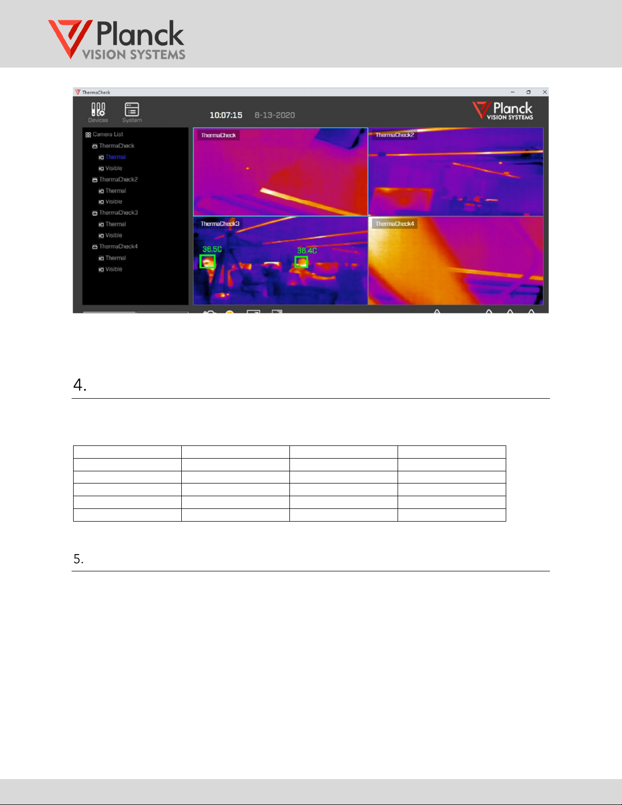
The ThermaCheck software can commun cate w th up to four cameras through a network sw tch. Most
routers have a sw tchboard of ethernet ports that can be used for th s purpose. S nce the
default IP
address of each ThermaCheck camera s the same, mult ple cameras must be added sequent ally to
the network w th each camera be ng reass gned a un que IP address. The steps requ red to do th s are
descr bed n Sect on 3.
Multi-camera network
The mult -camera network, as llustrated n F gure 1, cons sts of:
1. One computer runn ng the ThermaCheck Software
2. A sw tchboard of ethernet ports, one port for the computer and an add t onal port for each
ThermaCheck camera.
3. One to four ThermaCheck cameras
F gure 1: Mult -camera network
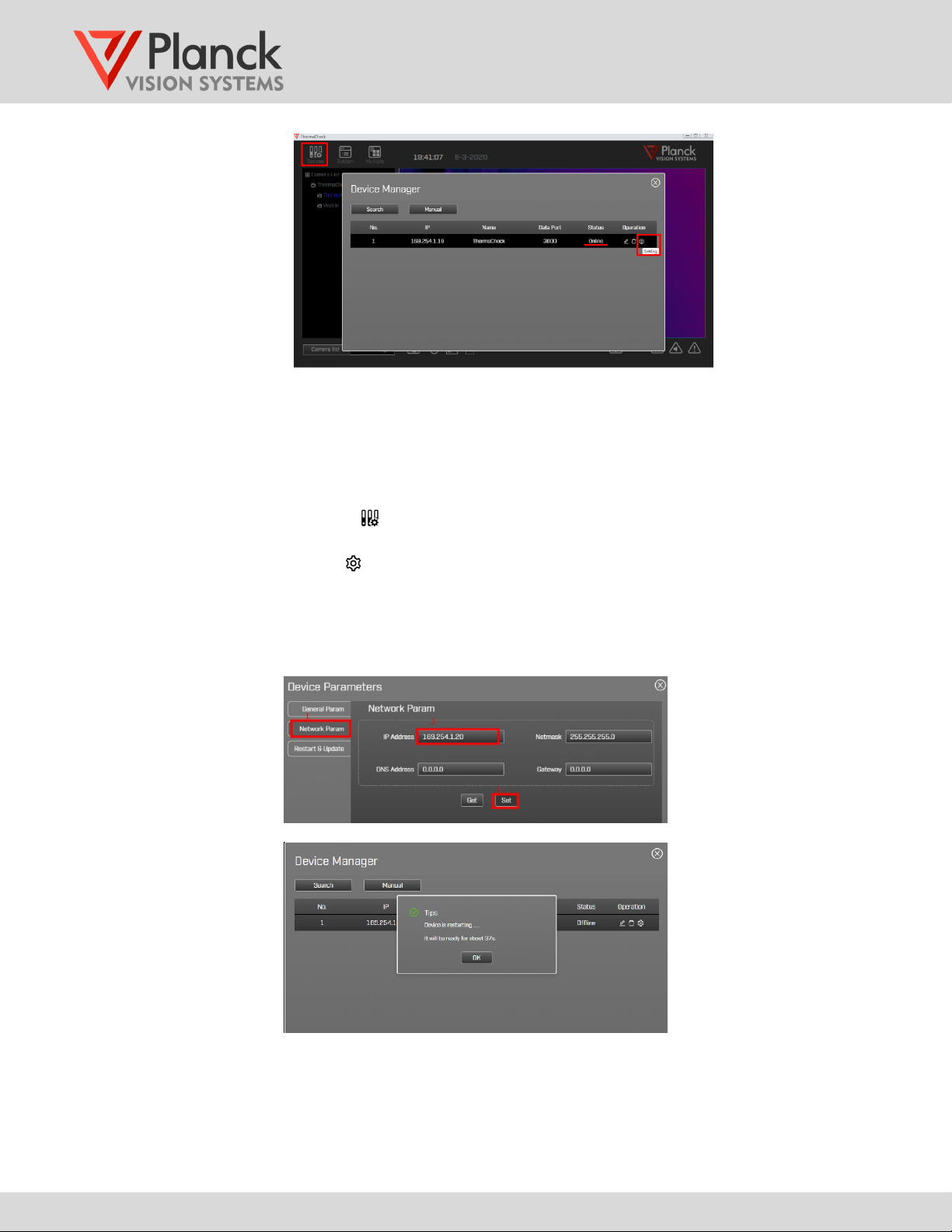
Steps for adding each new camera to the network
Mult ple cameras must be added sequent ally to the network w th each camera be ng reass gned a
un que IP address. The steps requ red to do th s are as follows.
Step 1
Connect the computer and one ThermaCheck camera to the ethernet ports on the sw tch panel as
shown n F gure 1. The prov ded USB-to-ethernet adapter may be used between the computer and
the sw tch panel ethernet ports. Most routers prov de a few ethernet sw tch ports. A larger number
may be obta ned by us ng a sw tch box.
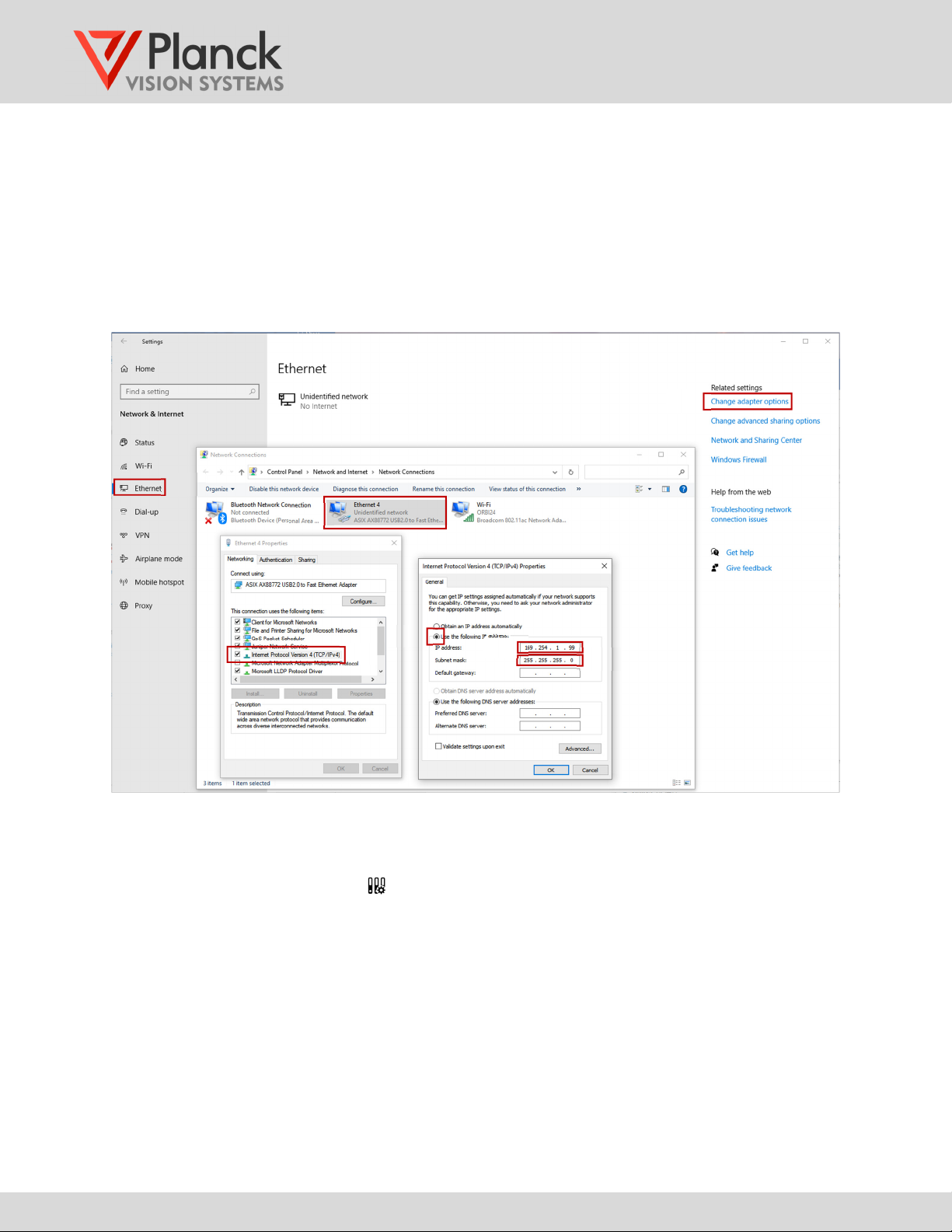
Step 2
Th s step conf gures the IP address of the computer on the local network
1. Open the computer’s “Sett ngs” , choose “Network & Internet” and then select “Ethernet”
(F gure1-a). Choose "Change adapter opt ons" (F gure1-b) under related sett ngs.
Computer
ThermaCheck
c
ameras
Camera 1
Network sw tch
USB-to-
ethernet
adapter

TC160 / TC320
NETWORKING GUIDE
(v.1.8)
www.planckv s onsystems.com 3
2.
R ght-cl ck on the Ethernet (F gure1-c) and select “Propert es”. Note: If you are not using the
USB-to-ethernet adapter, right-click on the Local Area Connection (instead of thernet) and
select “Properties”. Double left-cl ck on "Internet Protocol Vers on (TCP/IPV4)" (F gure1-d).
3.
In the pop-up w ndow, select "Use the follow ng IP address" (F gure1-e) and set the IP address
to 169.254.1.99 (F gure1-f) and set the Subnet mask to: 255.255.255.0 (F gure1-g).
4.
To save the computer IP address sett ngs close out all the network pop-up w ndows by
cl ck ng [OK].
Figure 2: Network dialog box settings
5.
Start the ThermaCheck program. Once the program s runn ng, a s ngle v deo stream
correspond ng to the f rst camera should automat cally start.
6.
Open the Dev ce Manager n the ThermaCheck software. Conf rm that the camera status
s "Onl ne" and has the default IP address of 169.254.1.19, as shown n F gure 3.
(a)
(c)
(b)
(d) (f) (g)
(e)

TC160 / TC320
NETWORKING GUIDE
(v.1.8)
www.planckv s onsystems.com 4
Figure 3: Device management interface
Step 3
Reconf gure the last ThermaCheck camera added to the network before connect ng a new camera to
the network sw tch. To reconf gure the last camera:
1.
Open the Dev ce Manager n the ThermaCheck software. Conf rm that the status of the last
camera added s "Onl ne" and has the default IP address of 169.254.1.19.
2.
Cl ck the sett ngs button for the dev ce w th the default IP address and select the [Network
Param] page.
3.
In the IP Address Box, change the last two d g ts of IP to match the value n Table 1. Cl ck [Set]
to change the IP address. The camera w ll automat cally restart, beep ng three t mes on
complet on.
Figure 4: Device parameter setting interface

TC160 / TC320
NETWORKING GUIDE
(v.1.8)
www.planckv s onsystems.com 5
4.
Cl ck the [Manual] button n the Dev ce Manager w ndow. Enter a new
de ice name
and
IP
address
and cl ck [Add]. The camera w ll come onl ne w th the new IP address, wh le the
former IP address w ll reg ster as offl ne.
5.
Connect a new ThermaCheck camera to one of the ethernet ports on the sw tch panel.
Assum ng that the new camera has the default IP address (169.254.1.19), the new camera
should come onl ne automat cally.
Figure 5: Manually add device interface
Step 4
1. To add add t onal cameras, Repeat Step 3 for each camera. A total of four cameras can be
mon tored w th the ThermaCheck software.
2. Note that camera names can be mod f ed n the Dev ce Manager nterface. Select the penc l
con , to mod fy the text of the camera name as shown n F gure 6, and save the name by
select ng the d sk con .
Figure 6: Device list interface
3. When f n shed add ng cameras, close the Dev ce Manager to return to the ma n user nterface.

TC160 / TC320
NETWORKING GUIDE
(v.1.8)
www.planckv s onsystems.com 6
Figure 7: Main user interface after completing the multi-camera configuration
Recommended network configuration parameters:
The recommended network conf gurat on s shown n Table 1.
Table 1: Recommended network configuration
number name IP subnet mask
1 Computer 169.254.1.99 255.255.255.0
2 Camera 1 169.254.1.20 255.255.255.0
3 Camera 2 169.254.1.21 255.255.255.0
4 Camera 3 169.254.1.22 255.255.255.0
5 Camera 4 169.254.1.19 255.255.255.0
User interface functions with multi-cameras
For general software features and funct onal ty, please refer to the TC160/TC320 User Manual
(ThermaCheck and ThermaCheck Pro). Gu del nes for temperature screen ng d scussed n the
TC160/TC320 User Manual are appl cable to mult -camera operat on.
In mult -camera mode,
1) The d splay conta ns v deo from each camera n the Camera L st.
2) Only one “Selected Camera” s des gnated w th a l ght blue bound ng box around the
v deo.
3) The Selected Camera can be changed by select ng the des red v deo w ndow or camera
from the Camera L st us ng the left mouse button.

TC160 / TC320
NETWORKING GUIDE
(v.1.8)
www.planckv s onsystems.com 7
4) The follow ng funct ons are only supported for the Selected Camera (des gnated by the
l ght blue bound ng box):
•Capture (snap shot) button ,
•Thermal/v s ble v deo toggle button ,
•Expanded v deo button ,
•Ch ld W ndow funct on ,
•Cal brat on funct on .
5) The Expanded v deo button causes the Selected Camera v deo to become full screen.
If there s a dev ce alarm n th s state, the d splay w ll automat cally return to the 4-screen
mode.
Two mportant notes:
1) The Threshold Temperature sett ng s common to all cameras.
2) The cal brat on of cameras must be performed nd v dually. In mult -camera mode, the
cal brat on funct on appl es only to the Selected Camera (des gnated by the l ght blue
bound ng box).
Thank you
Thank you for your purchase of a ThermaCheck camera. We develop our products to del ver rel able,
long last ng performance, and want to make sure you are sat sf ed w th your purchase. For more
product nformat on v s t www.planckv s onsystems.com, and feel free to get n touch w th us at
nfo@planckv s onsystems.com w th quest ons, problems, and comments.
Other manuals for ThermaCheck TC160
2
This manual suits for next models
7
Table of contents
Other Planck VISION SYSTEMS Thermal Camera manuals

Planck VISION SYSTEMS
Planck VISION SYSTEMS ThermaCheck M1 User manual

Planck VISION SYSTEMS
Planck VISION SYSTEMS TNC Series Instruction manual

Planck VISION SYSTEMS
Planck VISION SYSTEMS PROTECTOWIRE PWTC100 Instruction manual

Planck VISION SYSTEMS
Planck VISION SYSTEMS ThermaCheck TC160 User manual

Planck VISION SYSTEMS
Planck VISION SYSTEMS TNC Series User manual

Planck VISION SYSTEMS
Planck VISION SYSTEMS ThermaCheck LT User manual

Planck VISION SYSTEMS
Planck VISION SYSTEMS THH960 User manual