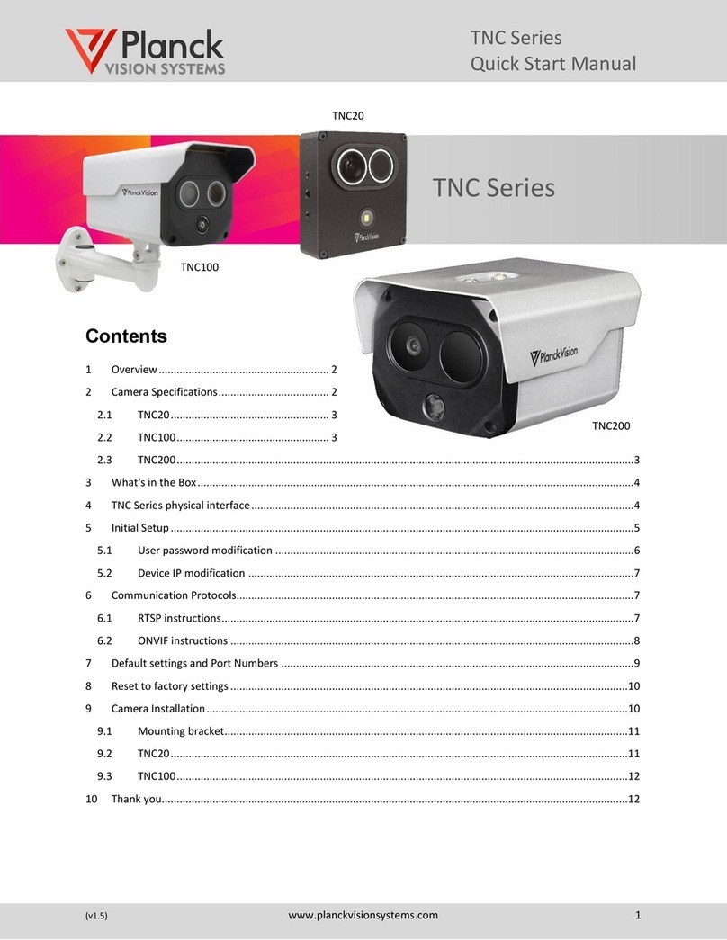
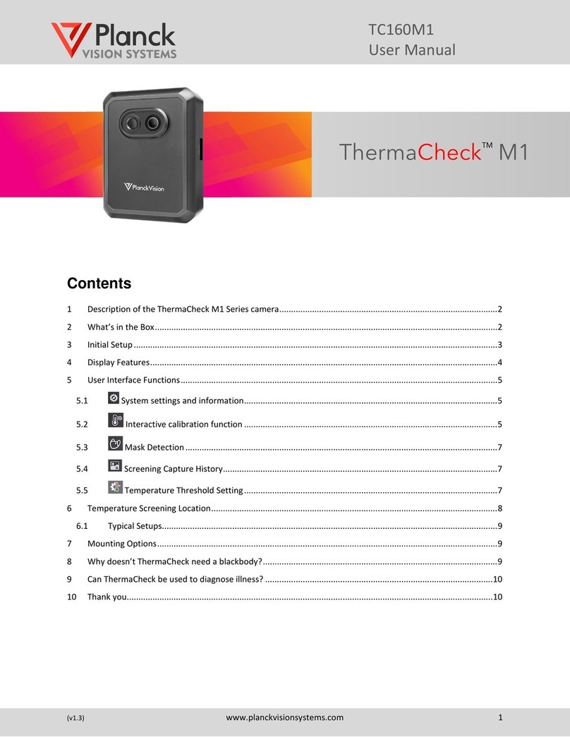
Planck VISION SYSTEMS TNC Series User manual

TNC Series
User Manual
(v1.4) www.planckvisionsystems.com 1
Contents
1Overview...............................................................................................................................................................2
2Camera Specifications...........................................................................................................................................2
2.1 TNC10...........................................................................................................................................................2
2.2 TNC200.........................................................................................................................................................3
3What's in the Box..................................................................................................................................................3
4TNC Series physical interface................................................................................................................................4
5Initial Setup...........................................................................................................................................................5
5.1 User password modification ........................................................................................................................6
5.2 Device IP modification .................................................................................................................................6
6Communication Protocols.....................................................................................................................................7
6.1 RTSP instructions..........................................................................................................................................7
6.2 ONVIF instructions .......................................................................................................................................8
7Default network settings ....................................................................................................................................10
8Thank you............................................................................................................................................................10
TNC Series

TNC Series
User Manual
(v1.4) www.planckvisionsystems.com 2
1Overview
Planck Vision Systems' dual-vision thermal network camera (TNC Series) can simultaneously record visible and
thermal images while collecting characteristic temperature information from the scene. It can be used in indoor
and outdoor environments for asset monitoring, intelligent security, and other applications. Through an IP
network, the TNC Series transmits collected data to PC clients or web browsers (Chrome) for real time surveillance
and alarm condition monitoring. SDK development kits are available to facilitate secondary development and
integration of Planck Vision Systems cameras with third-party platforms. The TNC series supports RTSP, RTP, TCP,
UDP, ONVIF and other general protocols, such as MODBUS to upload data to the client platform.
2Camera Specifications
Table 3-1 provides a list of features that are common to all cameras in the TNC Series. Planck Vision systems’
TNC10 cameras are an economical choice for a wide range of applications. The TNC200 cameras are built to
customers specifications.
Table 2-1: Common features*of the TNC Series
Network
Network Protocol
ICMP, TCP, UDP, RTP, RTSP, DHCP, PPPOE, UPNP,
DDNS, ONVIF, 802.1x, FTP, HTTP
User Rights
Three levels of user rights
Security Measures
User authentication (ID and PW)
Video Compression
H.264/H.265
Audio Compression
Audio G.711u/Intercom G.722
Mainstream
Visible: 1080p/720P with 30fps. Thermal: 25fps
Sub Stream
Visible: D1/CIF 30fps can be set. Thermal: 25fps
Smart Functions
Fire Detection
Supported
Temperature Measurement
4 temperature rule types (above high, below low, in between,
out of range)
Temperature Range
Temperature range -20°C to 550°C
Temperature Accuracy
Temperature accuracy: ±2°C or ±2%, whichever is greater
Perimeter Detection
Intrusion, line crossing, region entrance, region exiting
System Integration
Audio Input
1 Channel
Audio Output
1 Channel
Communication Interface
RJ45 10M/100M self-adaptive; RS485
Alarm Input
1 Channel
Alarm Output
1 Channel
Analog Video Output
PAL/NTSC/BNC
Built-in Onboard Storage
Optional
*Specifications are subject to change.
2.1 TNC10
This camera comes with a 160 x 120 uncooled microbolometer detector, a standard 57 x 48 field of view optics and
an IP67 rating bullet style housing.

TNC Series
User Manual
(v1.4) www.planckvisionsystems.com 3
2.2 TNC200
Model number for the TNC200 Series are given by:
TNC200-RES-HV-BT-IO
where ‘RES’, ‘HV’, ‘IP’ and ‘PT’ are placeholders for the following specifications:
•RES is the thermal sensor resolution. Standard options may include:
160 = 160 x 120
380 = 384 x 288
640 = 640 x 512
•HV is the horizontal field of view. For example, 57 means a 57°HVOF.
•BT is the camera body type (includes IP / other).
BU is bullet
PP is Planck Pro body
•IO interface options. Standard options include:
FF = full feature
IP = internet and power only
3What's in the Box
Table 3-1: Packing list
Serial
number
name
quantity
1
Camera
1
2
Power Adapter
1
3
Mounting screws
4
4
Expansion bolt
4
5
Allen wrench
1
6
Quick guide
1
7
Warranty Card
1
8
Certificate of
conformity
1

TNC Series
User Manual
(v1.4) www.planckvisionsystems.com 4
4TNC Series physical interface
The physical interface of the TNC series is shown in Figure 4-1. Cameras are provided with either a full-function or
a simple-function (network port and power port) tail cable according to customer's needs.
Figure 4-1: Appearance and interface diagram of dual-vision camera (TNC10 camera shown)
Table 4-1: Appearance and interface description
#
illustrate
Mark
Function description
1
Visible light lens
2
Infrared lens
3
Light sensor
For day and night mode detection
4
IR Illuminator
30 meters illumination for visible camera
5
Network Interface
LAN
Connect standard Ethernet cable
6
Power connector
DC 12V
Input DC 12V power supply
7
RS485 serial port
RS485
RS485
8
Audio input
AUDIO IN
Input audio signal, receives analog audio signal from
pickups and other equipment
9
Audio output
AUDIO OUT
Output audio signal to speakers and other
equipment
10
Alarm input channel
ALARM IN
1 alarm input interface
1 is ALM_IN+, 2 is ALM_IN- (Internally connected to
GND)
11
Alarm output channel
1&2
ALARM OUT
2 alarm output interfaces
1 is ALM_OUT1, 2 is ALM_OUT1_GND;
3 is ALM_OUT2, 4 is ALM_OUT2_GND.
12
AV analog video
output
VIDEO
Output analog video signal, which can be connected
to a monitor

TNC Series
User Manual
(v1.4) www.planckvisionsystems.com 5
5Initial Setup
•Step 1: After connecting camera power and the network ports between the camera and the computer,
please make sure that the camera IP address (192.168.1.19 by default) and the PC's IP address are in the
same network segment.
•Step 2: Open the Chrome browser, enter the device IP address in the address bar, and press [Enter] key.
When logging on with the browser interface for the first time, use the camera's default IP address.
•Step 3: When connecting to the camera for the first time, enter the default user name: 888888 and
password: 888888 and click "OK" (Figure 5-1).
•Step 4: The first time the Web Interface is used, the video preview may not work. To remedy, download
and install the required video file from the link provided in the header bar of the web interface.
•Step 5: The main page of the web interface is shown in Figure 5-2. This interface can be used to configure
the camera settings, preview video streams, and view all logged events.
Figure 5-1: Chrome login interface
Figure 5-2: Web interface main page

TNC Series
User Manual
(v1.4) www.planckvisionsystems.com 6
5.1 User password modification
To change the default user names and passwords, select the Setting tab, Basic tab and User Management tab, as
shown in Figure 5-3. Click "OK" to save any changes.
Figure 5-3: User/Password management interface
5.2 Device IP modification
To change the camera IP address, select the Setting tab, Network tab and IP Address & Port tab, as shown in
Figure 5-4. Click "OK" to save changes. Restart the device for the new IP address to take effect.
Figure 5-4: IP address and port interface

TNC Series
User Manual
(v1.4) www.planckvisionsystems.com 7
6Communication Protocols
The Planck Vision Systems TNC Series supports RTSP, RTP, TCP, UDP, ONVIF and other general protocols, such as
MODBUS data transfer. RTSP and ONVIF protocols are commonly used for cameras connected to Network Video
Recorders (NVR). Select illustrations for testing these protocols are provided in the following sections.
6.1 RTSP instructions
The RTSP protocol can be tested with VLC media player. (Note: When using the vlc-3.0.12-win64.exe, you will
experience a delay in the video stream caused by the player. The video will not be delayed when connecting to an
NVR system.) The rtsp address of the camera is:
TNC10 streams
Visible main stream: rtsp://192.168.1.19:354/0/888888:888888/main
Visible sub stream: rtsp://192.168.1.19:354/0/888888:888888/sub
Thermal main stream: rtsp://192.168.1.19:354/1/888888:888888/main
Thermal sub stream: rtsp://192.168.1.19:354/1/888888:888888/sub
TNC200 streams
Visible main stream: rtsp://192.168.1.19:554/0/888888:888888/main
Visible sub stream: rtsp://192.168.1.19:554/0/888888:888888/sub
Thermal main stream: rtsp://192.168.1.19:554/1/888888:888888/main
Thermal sub stream: rtsp://192.168.1.19:554/1/888888:888888/sub
The following steps may be used to test the RTSP protocol using the VLC media player:
1. Install the VLC media player.
2. After installation is complete, open the media player and refer to Figure 6-1.
3. Click "Media"-"Open network streaming"-"Enter the network URL (that is, the above rtsp address)"-click
"Play", wait for about 30 seconds. A real-time video stream will appear.
TNC Series
User Manual
(v1.4) www.planckvisionsystems.com 8
Figure 6-1: RTSP protocol with VLC media player
6.2 ONVIF instructions
The open source ONVIF Device Manager tool (version: odm-v2.2.250) can be used to test the ONVIF protocol. The
following steps are taken for this test:
1. Install and run the onvif device manager (odm-v2.2.250)
2. The camera should automatically appear in the Device list (Figure 6-2)
3. Enter the login user name (admin) and password (******) of your camera and click "Log in"
4. Select your "IP-Camera" then click "Live video" under NVT, corresponding to the visible (V_SRC_000) or
the thermal (V_SRC_001) video stream (Figure 6-3).
Figure 6-2: Login step for ONVIF Device Manager
1
2
3
4

TNC Series
User Manual
(v1.4) www.planckvisionsystems.com 10
7Default settings
Table 7-1: Network settings and port numbers
Parameter
Defaults (TNC10/200)
IP address
192.168.1.19
Subnet mask
255.255.255.0
Gateway
192.168.1.1
Transmission start port
3000
Data control port
3001
Remote playback port
3002
Web port
80
Multicast address
235.1.1.1
Multicast port
6500
RTSP
354/554
ONVIF
8000
Table 7-2: Default user settings
User
Name
Password
Administrator
888888
888888
Advanced
666666
666666
Ordinary
333333
333333
8Thank you
Thank you for purchasing a Planck Vision Systems TNC series product. We develop our products to deliver reliable,
long lasting performance, and want to make sure you are satisfied with your purchase. For more product
information visit www.planckvisionsystems.com, and feel free to get in touch with us at
info@planckvisionsystems.com with questions, problems, and comments.
Other manuals for TNC Series
1
This manual suits for next models
4
Table of contents
Other Planck VISION SYSTEMS Thermal Camera manuals

Planck VISION SYSTEMS
Planck VISION SYSTEMS THH960 User manual

Planck VISION SYSTEMS
Planck VISION SYSTEMS PROTECTOWIRE PWTC100 Instruction manual

Planck VISION SYSTEMS
Planck VISION SYSTEMS ThermaCheck LT User manual

Planck VISION SYSTEMS
Planck VISION SYSTEMS TNC Series Instruction manual

Planck VISION SYSTEMS
Planck VISION SYSTEMS ThermaCheck M1 User manual

Planck VISION SYSTEMS
Planck VISION SYSTEMS ThermaCheck TC160 User manual

Planck VISION SYSTEMS
Planck VISION SYSTEMS ThermaCheck TC160 User manual