Planck VISION SYSTEMS PROTECTOWIRE PWTC100 Instruction manual

1
PWTC100 Dual Vision
Thermal Camera
Quick Start Manual
MAN-2012-1223

2
PWTC100 Dual Vision Thermal Camera
MAN-2012 Published: 8/8/2023
Last modied 12/5/2023
© 2023 The Protectowire Company, Inc.
60 Washington Street Pembroke, MA 02359
781-826-3878 • Fax: 781-826-2045
sales@protectowire.com
www.Protectowire.com
PWTC100 Dual Vision Thermal Camera
Quick Start Manual

3
Table of Contents
PWTC100 Dual Vision Thermal Camera
1 Overview....................................................................................................................
2 PWTC100 Camera Specications.................................................................
3 What’s in the Box....................................................................................................
4 Physical interface...................................................................................................
5 Initial Setup...............................................................................................................
5.1 User password modication...............................................................
5.2 Device IP modication..........................................................................
6 Communication Protocols.................................................................................
6.1 RTSP instructions...................................................................................
6.2 ONVIF instructions.................................................................................
7 Default settings......................................................................................................
8 Troubleshooting......................................................................................................
4
4
5
5
6
7
7
8
8
9
10
10

4
PWTC100 Dual Vision Thermal Camera
1 Overview
Protectowire’s dual-vision thermal camera can simultaneously record visible and thermal images while
collecting characteristic temperature information from the scene. It can be used in indoor and outdoor
environments for asset monitoring, early warning heat detection, intelligent security, and other applications.
Through an IP network, the thermal camera transmits collected data to PC clients or web browsers (Chrome)
for real time surveillance and alarm condition monitoring. A JSON restful API is available to facilitate
secondary development and integration of the PWTC100 camera with third party platforms. The camera
supports RTSP, RTP, TCP, UDP, ONVIF and other general protocols, such as ONVIF and MODBUS to make
integration easy.
2 Camera Specifications
Table 2-1 provides a list of features that are available on the camera. This camera is a high featured camera
with the option for wireless network congurations.
Table 2-1: Features*
Network
Network Protocol HTTP, RTP, RTSP, FTP
User Rights Three levels of user rights
Security Measures User authentication (ID and PW)
Video Compression H.264/H.265
Audio Compression Audio G.711u/Intercom G.722
Functions
Fire Detection Supported
Temperature Measurement 4 temperature rule types (above high, below low, in between,
out of range)
Temperature Measurement Range -4°F to 1022°F (-20°C to 550°)
Temperature Accuracy 3.6°F or ±2% (±2°C or ±2%)
Perimeter Detection Intrusion, line crossing, region entrance, region exiting
System
Integration
Audio Input 1 Channel
Audio Output 1 Channel
Communication Interface RJ45 10M/100M self-adaptive; RS485
Alarm Input 1 Channel
Alarm Output 1 Channel (minimum)
Analog Video Output PAL/NTSC/BNC
Built-in on Head Storage Optional
* Specications are subject to change.
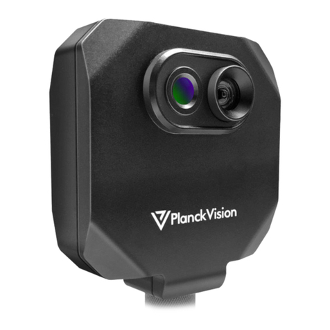
2.1 PWTC100 Resolution and Housing
This camera comes with a 256×192 uncooled microbolometer detector,
a standard 56 x 42 eld of view optics and a NEMA 4x / IP66 rating
housing.
5
PWTC100 Dual Vision Thermal Camera
3 What’s in the Box
4 Physical interface
The physical interface of the camera
is shown in Figure 4-1. The camera is
provided with a full function pigtail and
the IO interfaces listed in Table 4-1.
Serial Number Name Quantity
1 Camera 1
2 Power Adapter 1
7 Warranty Card 1
8Certicate of conformity 1
Table 3-1: Packing list
12 710 11 6 8 19 45 2
Figure 4-1: Appearance and interface diagram of dual-vision camera
Table 4-1: Appearance and interface description
PWTC100
# Illustrate Mark Function description
1 Visible light window Sensor lens over 1/2.7 inches CMOS
2 Infrared window Sensor lens over Uncooled Focal Plane Detector
3 IR Illuminator * For use with PWTC20
4 Network Interface LAN Connect standard Ethernet cable. POE available with PWTC100C
5 Power connector DC VDC Input DC 24V power supply for PWTC100F. 12VDC for the PWTC100C
6 RS485 serial port RS485 RS485
7 Audio input AUDIO IN Input audio signal, receives analog audio signal from pickups and other
equipment
8 Audio output AUDIO OUT Output audio signal to speakers and other equipment
9 Alarm input channel ALARM IN 1 alarm input interface 1 is ALM_IN+, 2 is ALM_IN-
(Internally connected to GND)
10 Alarm output channel 1 ALARM OUT 2 alarm output interfaces1 is ALM_OUT1, 2 is ALM_OUT1_GND;
11 AV analog video output VIDEO Output analog video signal, which can be connected to a monitor

6
Figure 5-1: Chrome login interface
Figure 5-2: Web interface main page
PWTC100 Dual Vision Thermal Camera
5 Initial Setup
• Step 1: After connecting camera power and the network ports between the camera and the computer,
please make sure that the camera IP address (192.168.1.19 by default) and the PC’s IP address are in the
same network segment.
• Step 2: Open the Chrome browser, enter the device IP address in the address bar, and press [Enter] key.
When logging on with the browser interface for the rst time, use the camera’s default IP address.
• Step 3: When connecting to the camera for the rst time, enter the default user name: 888888 and pass-
word: 888888 and click “OK” (Figure 5-1).
• Step 4: The rst time the Web Interface is used, the video preview may not work. To remedy, download and
install the required video le from the link provided in the header bar of the web interface.
• Step 5: The main page of the web interface is shown in Figure 5-2. This interface can be used to congure
the camera settings, preview video streams, and view all logged events.

7
PWTC100 Dual Vision Thermal Camera
5.1 User password modication
To change the default user names and passwords, select the Setting tab, Basic tab and User Management
tab, as shown in Figure 5-3. Click “OK” to save any changes.
5.2 Device IP modication
To change the camera IP address, select the Setting tab, Network tab and IP Address & Port tab, as shown
in Figure 5-4. Click “OK” to apply changes. Restart the device for the new IP address to take eect.
Figure 5-3: User/Password management interface
Figure 5-4: IP address and port interface

8
The PWTC camera supports RTSP, RTP, TCP, UDP, ONVIF and other general protocols, such as MODBUS
data transfer. RTSP and ONVIF protocols are commonly used for cameras connected to Network Video
Recorders (NVR). Select illustrations for testing these protocols are provided in the following sections.
6.1 RTSP instructions
The RTSP protocol can be tested with the VLC media player. The rtsp addresses of the camera are:
Note: the user/password elds should be modied if the Onvif/RTSP user management credentials have
been changed.
The following steps may be used to test the RTSP protocol using the VLC media player:
1. Install the VLC media player.
2. After installation is complete, open the media player and refer to Figure 6-1.
3. Click “Media”-”Open network streaming”-”Enter the network URL (that is, the above rtsp address)”-
click “Play”, wait for about 30 seconds. A real-time video stream will appear.
PWTC100 Dual Vision Thermal Camera
6 Communication Protocols
Figure 6-1: RTSP protocol with VLC media player

9
PWTC100 Dual Vision Thermal Camera
6.2 ONVIF instructions
The open source ONVIF Device Manager tool (version: odm-v2.2.250) can be used to test the ONVIF
protocol. The following steps are taken for this test:
1. Install and run the Onvif device manager (odm-v2.2.250)
2. The camera should automatically appear in the Device list (Figure 6-2)
3. Enter the login username (admin) and password (123456) of your camera and click “Log in”
4. Select your “IP-Camera” then click “Live video” under NVT, corresponding to the visible (V_SRC_000)
or the thermal (V_SRC_00l) video stream (Figure 6-3).
Figure 6-2: Login step for ONVIF Device Manager
Figure 6-3: Live video from ONVIF Device Manager

10
PWTC100 Dual Vision Thermal Camera
7 Default Settings
Table 7-1: Network settings and port numbers
Table 7-2: Default user settings
Table 7-3: Default Onvif/RTSP settings
Parameter Defaults (PWTC20F, PWTC100F, PWTC100C)
IP address 19 2 .16 8 .1.19
Subnet mask 255.255.255.0
Gateway 19 2 .16 8 .1.1
Transmission start port 3000
Data control port 3001
Remote playback port 3002
Web port 80
Multicast address 2 3 5 .1.1.1
Multicast port 6500
Modbus Server Port 502
TCP Server Port 31111
RTSP 554
ONVIF 8000
User Name Password
Administrator 888888 888888
Advanced 666666 666666
Ordinary 333333 333333
Name Password
Admin 123456
8 Reset to Factory Settings
To reset camera back to the factory settings (including the IP address: 192.168.1.19) use the following steps:
1. Unplug camera power
2. Remove small panel on bottom of camera (two Phillip screws)
3. Press and hold reset button 20 seconds while powering up camera
4. Replace panel on bottom of camera

11
PWTC100 Dual Vision Thermal Camera
9 Camera Installation
Pre-installation instructions
1. Before installation, please check whether the equipment and accessories in the packing box are complete and intact
against the packing list.
2. The installation wall should be able to bear at least 3 times the total weight of the bracket and the camera.
3. Please try to avoid installing the camera facing strong lighting and backlight scenes.
4. Before installation, please conrm that the power of the camera is disconnected.
5. Prepare all installation accessories and tools before installing the camera.
9.1 Mounting Illustration

12
PWTC100 Dual Vision Thermal Camera
Notices
© The Protectowire Company, Inc.
No part of this manual may be reproduced in any form or by any means (including electronic storage and retrieval or
translation into a foreign language) without prior agreement and written consent from The Protectowire Company, Inc. as
governed by US and international copyright laws.
The Protectowire Company, Inc.
60 Washington Street
Pembroke, MA 02359 USA
Subject Matter
The material in this document is subject to change without notice.
The Protectowire Company, Inc. makes no warranty of any kind with regard to this printed material, including, but not
limited to, the implied warranties of merchantability and tness for a particular purpose.
The Protectowire Company, Inc. shall not be liable for errors contained herein or for incidental or consequential damages
in connection with the furnishing, performance, or use of this material.
Printing History
New editions are complete revisions of the guide reecting alterations in the functionality of the instrument. Updates are
occasionally made to the guide between editions. The date on the title page changes when an updated guide is published.
To nd out the current revision of the guide, or to purchase an updated guide, contact your Protectowire Company
representative.
Warranty
When used specically, as set forth above, materials and equipment furnished by The Protectowire Company, Inc. are
warranted against inherent defects in materials or workmanship for two years from the date of shipment from Seller’s
F.O.B. location. However, as to either, it is Buyer’s responsibility to make an immediate claim to the company transporting
equipment for cracked or otherwise damaged units. This warranty is limited to repair or replacement (at Seller’s option)
at the factory or parts found upon inspection to have been inherently defective, and it specically excludes any and all
other costs, charges, or claims of any kind whatsoever. Seller makes no other warranties or representations of any
kind, expressed or implied, and seller disclaims any and all implied warranties, including without limitation those
of merchantability and tness for a particular purpose. Under no circumstances will seller be responsible for
indirect, incidental or consequential damages of any kind whatsoever. Acceptance of this agreement is express
acceptance of this section.
Table of contents
Other Planck VISION SYSTEMS Thermal Camera manuals

Planck VISION SYSTEMS
Planck VISION SYSTEMS ThermaCheck M1 User manual

Planck VISION SYSTEMS
Planck VISION SYSTEMS ThermaCheck LT User manual

Planck VISION SYSTEMS
Planck VISION SYSTEMS ThermaCheck TC160 User manual

Planck VISION SYSTEMS
Planck VISION SYSTEMS ThermaCheck TC160 User manual

Planck VISION SYSTEMS
Planck VISION SYSTEMS TNC Series Instruction manual

Planck VISION SYSTEMS
Planck VISION SYSTEMS TNC Series User manual

Planck VISION SYSTEMS
Planck VISION SYSTEMS THH960 User manual