Planck VISION SYSTEMS THH960 User manual

THH960
User Manual
(v1.6) www.planckvisionsystems.com ii
Forward
Dear users, thank you for choosing Planck Vision Systems’ THH960 hand-held camera. Before
using, please read this document carefully to familiarize yourself with product-related
knowledge and precautions. We develop our products to deliver reliable, long lasting
performance, and want to make sure you are satisfied with your purchase. For more product
information visit www.planckvisionsystems.com, and feel free to get in touch with us at
info@planckvisionsystems.com with questions, problems, and comments.
Symbol Notation
The following symbols appear in this manual, and their meanings are as follows:
Symbol
Description
Used to alert you to potentially hazardous
situations which, if not avoided, could result in
personal injury.
Used to alert you to situations which, if not
avoided, could result in damage to the camera,
reduced camera performance, data loss, or other
unpredictable results.
Used to highlight important information and
practical tips to ensure optimal camera operation.
Safety Precautions
Before using your new camera, please read carefully and strictly abide by the following safety
information so as to avoid personal injury, property damage, and other hazards.
•Be sure to use the battery as intended. Batteries may catch fire or explode if misused. If
you need to replace the battery, be sure to use the same type of battery as the original.
•Be sure to use a charging cord and power adapter that meets the appropriate standard
and is used within its rating.
•Please ensure that the power supply voltage is stable and meets the power supply
requirements of the device.
•If the device emits smoke, odor or noise, please power off and disconnect the power
supply immediately.

THH960
User Manual
(v1.6) www.planckvisionsystems.com iii
•Because the camera uses a very sensitive thermal sensor, do not point the lens directly
at a strong radiation source (such as the sun, direct or reflected laser beams, etc.) under
any circumstance (camera on or off), otherwise the thermal sensor will be permanently
damaged!
•The original packaging must be used during transportation. Strong impacts to the
camera during use or transportation may cause damage.
•When storing the camera, it is recommended to use the original packaging box and
place it in a cool, dry, ventilated environment without strong electromagnetic fields.
•Avoid contaminating the lens surface with oils and other chemical substances. After use,
please close the lens cap.
•Do not operate the camera in a temperature environment exceeding +50°C (+122°F).
•To prevent the potential danger of data loss, please copy (back up) your camera’s data
to your computer regularly.
•Do not open the camera body or make modifications without authorization, and
maintenance can only be carried out by the authorized personnel of Planck Vision
Systems.
•Please do not look directly at the laser pointer beam. Laser beams can cause eye injury.
•After the device is turned on, it may take about 10 minutes to warm up before it’s ready
for accurate readings.
•Adjust thermal lens focus before making temperature measurements to optimize the
performance of the camera.
•Every camera is temperature calibrated at the factory.
Content
Forward .................................................................................................................................................ii
Symbol Notation ..............................................................................................................................ii
Safety Precautions............................................................................................................................ii
Content ................................................................................................................................................iii
1THH960 Camera...........................................................................................................................7
1.1 Camera introduction ............................................................................................................7
1.2 Camera features ...................................................................................................................7
1.3 Body appearance and interface..........................................................................................7
1.3.1 Front view.......................................................................................................................7
1.3.2 Back view .......................................................................................................................8
1.3.3 Right side view ..............................................................................................................9

THH960
User Manual
(v1.6) www.planckvisionsystems.com iv
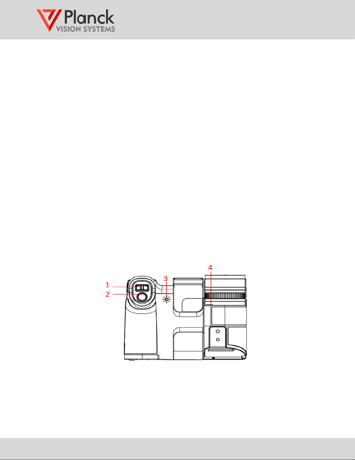
1.3.4 Left side view .............................................................................................................. 10
1.3.5 Top view...................................................................................................................... 10
1.3.6 Bottom view................................................................................................................ 11
2Operation guide........................................................................................................................ 11
2.1 Preparation before operation .......................................................................................... 11
2.1.1 Charging ..................................................................................................................... 11
2.1.1.1 External charger ................................................................................................. 11
2.1.1.2 USB charging ...................................................................................................... 12
2.1.2 Lens replacement....................................................................................................... 13
2.1.3 Adjust thermal focus.................................................................................................. 13
2.1.4 Lens barrel rotation.................................................................................................... 14
2.1.5 Viewfinder eyepiece .................................................................................................. 14
2.1.6 Shoulder strap............................................................................................................ 15
2.2 Startup................................................................................................................................. 15
2.3 Shutdown............................................................................................................................ 15
3User interface............................................................................................................................. 15
3.1 Home screen ...................................................................................................................... 15
3.1.1 On-screen display (OSD)........................................................................................... 15
3.1.2 Home screen menu.................................................................................................... 18
3.1.2.1 Overview of user interface icons ...................................................................... 18
3.1.3 Temperature scale setting .................................................................................... 19
3.1.4 Palette setting ......................................................................................................... 19
3.1.5 Alarm settings ........................................................................................................ 20
3.1.5.1 Above temperature alarm ................................................................................. 21
3.1.5.2 Below temperature alarm.................................................................................. 21
3.1.5.3 Between temperatures alarm............................................................................ 21
3.1.5.4 Outside temperatures alarm............................................................................. 21
3.1.5.5 Temperature difference alarm.......................................................................... 22
3.1.6 System settings ...................................................................................................... 22
3.1.7 Display mode , ................................................................................................. 22
3.1.8 Capture button , ................................................................................................. 22
3.1.9 Image/Video gallery ............................................................................................ 23
3.1.9.1 Gallery action functions , , , , ................................................................ 24

THH960
User Manual
(v1.6) www.planckvisionsystems.com v
3.2 Measure/Capture menu ........................................................................................... 25
3.2.1 Global measurement parameters ........................................................................ 25
3.2.1.1 Emissivity ......................................................................................................... 25
3.2.1.2 Reflection temperature .................................................................................. 26
3.2.1.3 Ambient temperature .................................................................................... 27
3.2.1.4 Relative humidity ............................................................................................ 27
3.2.1.5 Measurement distance .................................................................................. 28
3.2.1.6 External optical transmittance ...................................................................... 28
3.2.1.7 External optical window temperature .......................................................... 29
3.2.2 Temperature measurement tools ....................................................................... 29
3.2.2.1 Add a temperature measurement region , , , ...................................... 30
3.2.2.2 Region measurement selection .................................................................... 30
3.2.2.3 Move and scale measurement region , ..................................................... 31
3.2.2.4 OSD settings for regional measurements ................................................... 31
3.2.2.5 Regional emissivity setting ............................................................................ 32
3.2.2.6 Add a temperature difference measurement ............................................. 32
3.2.2.7 Delete a temperature measurement region ............................................... 33
3.2.3 Capture mode ....................................................................................................... 34
3.2.3.1 Picture mode .................................................................................................. 34
3.2.3.2 Video mode .................................................................................................... 34
3.2.3.3 Interval mode ................................................................................................. 35
3.2.4 Thermal display mode ......................................................................................... 35
3.2.4.1 Thermal only .................................................................................................. 35
3.2.4.2 Picture-in-picture ........................................................................................... 36
3.2.4.3 Fusion ............................................................................................................. 36
3.2.5 Operational settings .............................................................................................. 37
3.2.5.1 OSD display/hide switch ............................................................................... 37
3.2.5.2 Flashlight on/off switch .................................................................................. 37
3.2.5.3 Visible camera on/off switch ......................................................................... 37
3.2.5.4 Sound volume ................................................................................................. 37
3.2.5.5 Screen brightness .......................................................................................... 38
3.2.5.6 Flat field correction ........................................................................................ 38
3.2.5.7 Laser pointer ................................................................................................... 38

THH960
User Manual
(v1.6) www.planckvisionsystems.com vi
3.2.5.8 Temperature range setting ........................................................................... 38
3.2.5.9 System settings ................................................................................................... 39
3.3 System settings .................................................................................................................. 39
3.3.1 Language, date & time.............................................................................................. 39
3.3.2 Temperature and distance units .............................................................................. 41
3.3.3 On Screen Display ..................................................................................................... 42
3.3.4 Digital Imagery & Save .............................................................................................. 43
3.3.5 Auxiliaries.................................................................................................................... 44
3.3.6 Network....................................................................................................................... 45
3.3.7 Temperature range setting....................................................................................... 46
3.3.8 Power Save ................................................................................................................. 47
3.3.9 System ......................................................................................................................... 47
4Radiometric image analysis ..................................................................................................... 48
4.1 On camera analysis ........................................................................................................... 48
4.2 IrAnalysisTools software ................................................................................................... 49
4.3 Annotate thermal image files ........................................................................................... 49
4.3.1 Voice annotation .................................................................................................... 50
4.3.2 Text annotation .................................................................................................... 51
5Camera Maintenance................................................................................................................ 51
5.1 Cleaning the housing/cables and other parts................................................................ 51
5.2 Cleaning thermal lens ....................................................................................................... 51
5.3 Lithium battery maintenance............................................................................................ 52
6Emissivity Data........................................................................................................................... 52
7Statements ................................................................................................................................. 53

THH960
User Manual
(v1.6) www.planckvisionsystems.com 7
1THH960 Camera
1.1 Camera introduction
The THH960 camera is a high-performance handheld infrared camera designed for
precise radiometric temperature measurements. This camera integrates a high-sensitivity
infrared thermal detector and a high-resolution visible detector to couple accurate
temperature measurements with excellent imaging. The ergonomic design of the
THH960 makes this handheld camera perfect for field surveys in electric power,
petrochemical, rail transit, and metallurgy industries, where preventative detection of
temperature anomalies is required.
1.2 Camera features
•5.5” 1080P high-definition display;
•Supports multiple display modes including thermal only, visible only, picture-in-picture,
and image fusion;
•Supports various temperature measurement geometries including point, line, frame,
and others;
•Supports multiple thermal lenses, with automatic lens recognition;
•Supports automatic and manual focus;
•Supports a variety of color palettes, and palette customization;
•Supports both audio and on display alarm alerts;
•Supports thermal image snapshots, thermal video recording, and secondary (off
camera) analysis.
1.3 Body appearance and interface
1.3.1 Front view
1. Flashlight button

THH960
User Manual
(v1.6) www.planckvisionsystems.com 8
2. Image gallery button
3. Programmable button (P2)
4. Power indicator
•Always on when power on, off when power off, fast flashing (twice a second) when
charging, slow flashing when fully charged (once a second).
5. Power button
•In the power-off state, a long press is required to turn on the camera.
•In the power-on state, a short press puts the camera into sleep mode; a long press
opens the selection menu for <shutdown>, <restart> or <cancel> options.
•In the sleep mode state, a short press is required to wake up the screen.
6. LCD touch screen
7. Ambient light sensor
8. Viewfinder switch
9. Programmable button (P1)
10. Return button
11. Microphone
12. Selection button and direction ring
•The middle button has the function of confirming a selection.
•The direction ring is used to advance a selection up, down, left and right.
1.3.2 Back view
1. Digital zoom button
•For each button movement to the right or left, the image zooms in or out by 0.1x; a long
press to the right or left for >2s supports continuous zooming in or out; release the
button to stop zooming.

THH960
User Manual
(v1.6) www.planckvisionsystems.com 9
In addition to zooming in and out with the digital zoom button, you can also
perform zoom operations on the screen.
•Three ways to zoom in and out on an image: touch the screen with two fingers and
spread them outward or inward; flick the dial on the screen to the left or right; tap the
+ or – sign display.
•When zoomed to 1x, the zoom icon is hidden.
2. Capture button
•The capture button supports two modes of still picture capture and two modes of video
capture.
•Still pictures can be taken in either a non-radiometric jpeg format or radiometric JPEG
format (see 3.2.3.1). The radiometric format supports temperature examination and
user annotations (voice and written).
Still pictures can be taken in interval mode where a series of images are taken at
a specified time interval (see 3.2.3.3).
•Videos can be taken in either a non-radiometric mpeg format or radiometric lcvr format
(see 3.2.3.2). The radiometric format supports temperature examination and user
annotations (voice and written).
3. Speaker
4. Change lens button
•Press this button to release the lens.
1.3.3 Right side view
1. Shoulder strap attachment point
2. Hand strap attachment point
3. Hand strap attachment point
4. Battery compartment

THH960
User Manual
(v1.6) www.planckvisionsystems.com 10
1.3.4 Left side view
1. Thermal image autofocus button
2. Laser pointer button
Do
not look directly into the laser beam, the laser beam may cause eye injury.
3. Focus ring for thermal image
4. Shoulder strap attachment point
1.3.5 Top view
1. Infrared thermal imaging lens
2. Visible camera
3. Flashlight
4. Laser pointer
Do not look directly into the laser beam, the laser beam may cause eye injury.
5. Second Flashlight
6. N/A to THH960 model

THH960
User Manual
(v1.6) www.planckvisionsystems.com 11
1.3.6 Bottom view
1. Micro HDMI interface
•Supports HDMI V2.0 protocol.
2. SD card indicator
•When the SD card is recognized, a green indicator light is on;
•During data communication, the indicator flashes at 2Hz.
3. SD card slot
•Supports SDXC.
4. SIM card slot
5. Charging port / USB 3.0 TYPE C
•Allows PC access to memory card and internal storage of images and videos.
2Operation guide
2.1 Preparation before operation
2.1.1 Charging
The battery can be charged with an external charger or through the USB port.
Before first use of the camera, charge the battery fully.
2.1.1.1
External charger
If quick charging is required, the battery of the camera can be removed and charged on
the external charger using the following steps:
Step 1 Use your thumb and forefinger to press the battery compartment latch inward
and pull the battery out.

THH960
User Manual
(v1.6) www.planckvisionsystems.com 12
Step 2 After confirming that the metal tabs at the bottom of the battery align with the
metal tabs of the charger, put the battery in the charger to charge. The battery
icon on the charger flashes to indicate that it is charging, and stops flashing to
indicate that the battery is fully charged.
Step 3 When charging is complete, unplug the battery from the charger.
Step 4 When installing, make sure that the metal tabs at the bottom of the battery align
with the metal tabs inside the battery compartment, and push the battery inward
to complete the battery installation.
Be sure to use original batteries, chargers, and power adapters.
2.1.1.2
USB charging
For convenient charging, you can connect the camera to the power adapter via a USB
cable.
Please leave the battery in the camera when charging through the USB port.
For charging through the USB port, use the following steps:
Step 1 Open the interface cover in the direction of the arrow illustrated.
Step 2 Connect one end of the USB cable to the camera and the other end to the power
adapter.

THH960
User Manual
(v1.6) www.planckvisionsystems.com 13
2.1.2 Lens replacement
Users can replace the thermal lens according to their actual needs. Only lenses
ordered with your THH960 camera may be used.
The camera lens may be replaced with the following steps:
Step 1 Confirm that the camera is turned off.
Step 2 Press the change lens button next to the lens.
Step 3 Rotate the front of the lens counterclockwise to remove the old lens.
Step 4 Align the red dots on the new lens and camera housing. Press in the lens and
rotate clockwise to install. The camera will automatically recognize the new lens
and complete the replacement.
2.1.3 Adjust thermal focus
The focus of the thermal image is manually adjusted with the following steps:

THH960
User Manual
(v1.6) www.planckvisionsystems.com 14
Step 1 Turn the focus ring clockwise (when facing the screen) to focus further from the
camera.
Step 2 Turn the focus ring counterclockwise (when facing the screen) to focus closer to
the camera.
The focus can be automatically adjusted using the physical button in the side of
the optical barrel (see 1.3.4 item 1).
2.1.4 Lens barrel rotation
The ergonomic camera design allows users to rotate the lens barrel according to the
needs of the working condition. When holding the camera with the right hand, be sure
to support the lens barrel with the left hand at the same time. This will greatly reduce the
fatigue of the right hand. Adjust the angle between the touch screen and the lens barrel
to an angle suitable for the working conditions (adjustable from 0 to 120°).
2.1.5 Viewfinder eyepiece
The viewfinder accessory may be installed when desirable for the working conditions.
To install the viewfinder:
Step 1 Slide viewfinder mounting cover out of the mount to remove it (Figure ②).
Step 2 Slide the viewfinder into the mount to complete installation (Figure ③).

THH960
User Manual
(v1.6) www.planckvisionsystems.com 15
2.1.6 Shoulder strap
Put the shoulder strap over the shoulder and neck to prevent the camera from
falling.
To install the shoulder strap:
Step 1 Thread the end of the shoulder strap through port-A of the zigzag buckle and
out through port-B.
Step 2 Pass the end of the strap through the attachment point on the camera, shown as
location-1 in the right-side camera view 1.3.3
Step 3 Pass the end of the strap back through port-B and then port-A a second time,
and pull tight.
Step 4 Repeat Steps 1-3 using the other end of the shoulder strap and second
attachment point on the camera, shown as location-4 in the left side camera view
1.3.4
2.2 Startup
Confirm that the battery is fully charged, and use a long press of the power button to
turn on the camera. After the startup is completed, the home screen is displayed.
2.3 Shutdown
Shutdown can be done manually or automatically.
•Manual shutdown: requires a long press of the power button to turn off the camera.
•Tap the system settings icon , enter the <Power Save> menu, select the <Shutdown>
menu, and set the automatic shutdown time according to your needs.
3User interface
The user interface offers a layered menu OS that can be navigated by either the touch screen,
or physical buttons on the camera. When navigating by physical buttons, the blue highlight
menu item on the display can be advanced using the direction ring and the next menu item
chosen with the selection button. The selection button and direction ring are seen in the
front view of the camera (see 1.3.1 item 12). To return from a submenu, press the return
button (see 1.3.1 item 10).
3.1 Home screen
3.1.1 On-screen display (OSD)
OSD is the abbreviation of On-Screen Display, which refers specifically to the text and
icon information displayed on the screen. The enumerated OSD icons shown in the
following figure are described in Table 3-1.

THH960
User Manual
(v1.6) www.planckvisionsystems.com 16
Table 3-1: Main screen OSD information
#
Name
Description
1
Laser on/off
status
Displayed means on, hidden means
off
Do not look directly into the
laser beam, the laser beam
may cause eye injury
2
Visible camera
on/off status
Displayed means on, hidden means
off
3
Flashlight on/off
status
Displayed means on, hidden means
off
4
Temperature
range setting
The high column icon
represents the high temperature
measurement range: 100~700 °C
The low column icon represents
the low temperature measurement
range: -40~150°C
5
Temperature
data overlay
Represented from left to right:
global maximum temperature
value, minimum temperature value,
average temperature value, center
spot temperature value
6
USB connection
status
Displayed means connected,
hidden means disconnected
7
Wi-Fi connection
status
Displayed means connected,
hidden means disconnected
8
GPS location
status
Displayed means on, hidden means
off

THH960
User Manual
(v1.6) www.planckvisionsystems.com 17
9
Bluetooth status /
Bluetooth
headset status
Displayed means on, hidden
means off
Displayed means Bluetooth
headset connected, hidden means
disconnected
10
Remaining
battery power
display
When the battery is lower than
20%, the icon color is displayed in
red
11
Global maximum
temperature
point
Red triangle marks the location
of global maximum temperature
12
Charging status
Display means connected, hidden
means disconnected
13
Color bar
maximum
The maximum temperature value
displayed by the color bar
14
Temperature
alarm indicator
Displayed when an temperature
measurement alarms is active
(please refer to 3.1.5)
15
Color bar
Color spectrum assigned to the
range of temperatures between
minimum and maximum values.
16
Color bar
minimum
The minimum temperature value
displayed by the color bar
17
Temperature
measurement
global
parameters
Can contain: Emissivity, Reflected
Temperature, Ambient
Temperature, Relative Humidity,
Measurement Distance, External
Optical Window Transmittance,
External Optical Window
Temperature, please refer to 3.2.1
18
Global minimum
temperature
point
Blue inverted triangle marks the
location of global minimum
temperature
19
Measure/Capture
menu access
Please refer to 3.2
20
Date and time
overlay
Default on, please refer to 3.3.3

THH960
User Manual
(v1.6) www.planckvisionsystems.com 18
3.1.2 Home screen menu
3.1.2.1
Overview of user interface icons
Table 3-2 provides an overview of the onscreen icons used in the menu interface.
Table 3-2: On screen menu icons
#
Name
Description
1
Automatic / Manual temperature scale
2
Palette settings
3
Alarm settings; sets alarm type and alarm
thresholds
4
System settings
5
Thermal/Visual display mode switch
6
Capture button
7
Image gallery
8
Measure/Capture main menu
9
Global measurement parameters
Emissivity, Reflected
Temperature, Ambient Temperature,
Relative Humidity, Measurement
Distance, External Optical Window
Transmittance, External Optical
Window Temperature
10
Temperature measurement tools
Measurement area selection
Definable temperature regions:
Center point, Any point, Line,
Rectangular, Ellipse

THH960
User Manual
(v1.6) www.planckvisionsystems.com 19
Measures the temperature difference
between two values
Delete region
11
Capture modes
Can select snapshot, recording,
or Continuous shooting mode
12
Thermal Image display mode
Can select from following modes:
thermal only, picture-in-picture,
fusion
13
Operational settings
OSD display/hide switch;
Flashlight on/off switch; Visible
camera on/off switch; Sound volume;
Screen brightness; Flat field
correction; Laser pointer;
Temperature range setting.
Icon names will pop up when using the direction ring and selection button (see
1.3.1 item 12) to navigate the onscreen menu.
For a complete and updated description of the user interface, please download the
THH960 user manual: https://www.planckvisionsystems.com/tnc-downloads/thh960
3.1.3 Temperature scale setting
Tap the temperature scale bar setting icon to toggle between Automatic and Manual
settings.
•In automatic mode, the upper and lower limits of the temperature scale bar will adjust
automatically to the temperature scene.
•In manual mode, the upper and lower limits of the temperature scale bar are adjustable
using the range wheel appearing next to the color bar scale. To adjust the temperature
scale, tap the upper and/or lower temperatures displayed at the ends of the color bar.
When selected, the temperature background color becomes an opaque gray. Slide the
range wheel up or down to adjust the temperature value(s). Tap the temperature scale
bar value a second time to lock its value. Both scale bar values must be in a locked state
to complete the setting.
3.1.4 Palette setting
Tap the icon on the home screen to enter the palette menu. Choose between the
standard palettes and a custom palette.

THH960
User Manual
(v1.6) www.planckvisionsystems.com 20
Table 3-3 provides reference names to the various color palettes.
Table 3-3: Palette Icons
White Hot
Black Hot
Iron Red
Rainbow
Globlow
Iron Red 1
Iron Red 2
Sepia
Color 1
Color 2
Ice Fire
Rainbow 1
Red Hot
Green Hot
Gray Red
Lava Red
Instalert
Aurora
Custom
3.1.5 Alarm settings
Tap the icon on the home screen to set the alarm mode and parameters for global
temperature measurements. Five different temperature alarm modes are supported:
Above, below, between, outside, and temperature difference. While there is an active
alarm condition, the icon flashes on screen.
An audible alert and/or alarm location display are optional settings for different alarm
types. To select either,
Step 1 Tap the home screen icon
Step 2 Turn on/off the audible alarm with the <Audible> submenu.
Step 3 Turn on/off the alarm location display using the <Location> submenu.
The alarm location display switches the color palette to white hot (see 3.1.4) and
the area in the scene that is triggering the alarm is displayed in red. This option
is unavailable for temperature difference alarm settings.
Table of contents
Other Planck VISION SYSTEMS Thermal Camera manuals

Planck VISION SYSTEMS
Planck VISION SYSTEMS ThermaCheck TC160 User manual

Planck VISION SYSTEMS
Planck VISION SYSTEMS ThermaCheck LT User manual

Planck VISION SYSTEMS
Planck VISION SYSTEMS TNC Series Instruction manual

Planck VISION SYSTEMS
Planck VISION SYSTEMS PROTECTOWIRE PWTC100 Instruction manual

Planck VISION SYSTEMS
Planck VISION SYSTEMS ThermaCheck TC160 User manual

Planck VISION SYSTEMS
Planck VISION SYSTEMS TNC Series User manual

Planck VISION SYSTEMS
Planck VISION SYSTEMS ThermaCheck M1 User manual