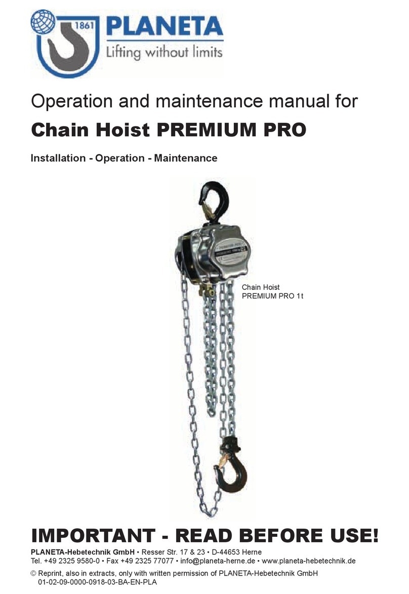
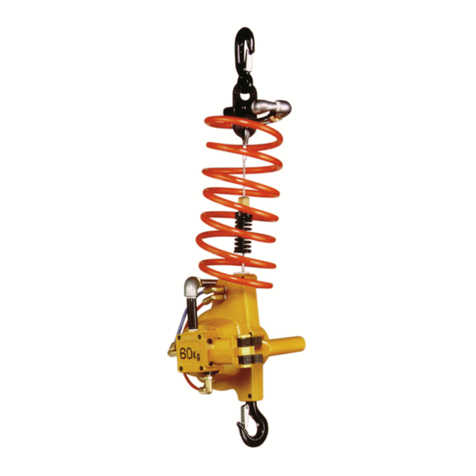
Planeta PKB Series User manual

Operation and maintenance manual for
Low headroom trolley hoist PKB
Installation - Operation - Maintenance
© Reprint, also in extracts, only with written permission of PLANETA-Hebetechnik GmbH
01-06-02-0000-0515-00-BA-EN-PLA
IMPORTANT - READ BEFORE USE!
PLANETA-Hebetechnik GmbH •Resser Str. 17 & 23 • D-44653 Herne

Introduction
This instruction manual is for an hoist trolley unit manufactured by PLANETA and contains
important information for safe, proper and economic use. Observance of the manual helps to avoid
dangerous situations, reduce repair costs, reduce downtimes and extend the service life of PLNETA
hoist trolley units.
If any question arises, which is not addressed in this instruction manual, please contact your local
authorised reseller or your contact person at PLANETA.
Important: Immediately upon delivery, inspect the product for any damage which
might have been caused during transportation.
Do NOT install or commission a damaged product!
Immediately report damage caused during transportation to PLANETA.
After inspection, damaged items must be repaired or replaced, before
installation and commissioning.
Assembly, installation, commissioning, tests and maintenance may only
be executed by competent persons!
Each operator must have read the entire manual and fully understand
its contents.
© Copyright 2015 by PLANETA. All rights reserved. No parts of this document may be
reproduced or transmitted in any form or by any means electronic or mechanical, including
photocopying and recording, for any purpose without the express written permission of
PLANETA.
PLANETA hoist trolley unit specifications
Write down your PLANETA hoist trolley unit specifications on this page. The specifications can be
found on the nameplate which is mounted to the Atlas hoist trolley unit. Year of manufacture :
Hoist manufacture no. :
Hoist model :
Trolley manufacture no. :
Trolley model :
2
2

Table of contents
Introduction...................................................................................................................
..... 2
1 Definitions .................................................................................................................
... 5
2 Safety instructions .........................................................................................................
6
2.1 Symbols............................................................................................................ 6
2.2 Safety precautions.............................................................................................. 7
2.3 Purpose of use ................................................................................................... 7
2.4 Inappropriate use ............................................................................................... 7
2.5 Safe operation ................................................................................................... 7
2.6 Proper load attachment / suspension .................................................................... 8
2.7 Installation, commissioning, maintenance and repairs............................................. 8
2.8 Periodic inspection and tests ................................................................................ 8
3 General information ....................................................................................................... 9
3.1 Technical specification......................................................................................... 9
3.2 Factory warranty ................................................................................................ 9
3.3 Safe Working Load ............................................................................................. 9
3.4 Areas of application ............................................................................................ 9
3.5 Trolley nameplate designation.............................................................................10
3.6 Trolley model designation
...................................................................................10
3.7 Hoist nameplate designation ...............................................................................11
3.8 Hoist model designation .....................................................................................11
3.9 Product overview and dimensions........................................................................12
3.9.1 Standard headroom ...........................................................................................12
3.9.2 Low headroom ..................................................................................................15
3.9.3 Ultra low headroom ...........................................................................................17
4 Transport and Storage...................................................................................................19
5 Installation ................................................................................................................
..20
6 Commissioning .............................................................................................................23
7 Operation ...................................................................................................................
.24
8 Maintenance.................................................................................................................2
6
8.1 Maintenance schedule ........................................................................................26
8.2 Lubrication list ..................................................................................................27
8.3 Lubrication codes ..............................................................................................28
8.4 Tightening torques ............................................................................................29
8.5 Chain ...............................................................................................................30
8.6 Hook................................................................................................................31
9 Malfunctions.................................................................................................................
33
10 Taking out of operation .........................................................................................34
11 Spare parts..........................................................................................................35
3
3

4
11.1 Standard headroom ...........................................................................................35
11.1.1 Model K hoist ................................................................................................38
11.1.2 Model N hoist ................................................................................................43
11.2 Low headroom ..................................................................................................48
11.3 Ultra low headroom ...........................................................................................49
Appendix I. Logbook ...............................................................................................51
Appendix II. Technical specifications ..........................................................................52
4

5
1 Definitions
The following definitions are used in this manual:
Product Wherever the term “product” is used this means the hoist
trolley unit.
Hoist trolley unit A hoist trolley unit means an trolley combined with an
chain hoist to executed as a single unit with a standard
headroom, low headroom or ultra low headroom.
Operators Operators are persons who use and control the product.
They are well trained and conscious of the risks which
may arise during operation and incorrect usage. Operators
are well aware of the precautions, prevailing conditions
and applicable regulations. They have proven their ability
by experience and are authorised to control the product.
Competent person’s Competent persons have a theoretical basis as well as a
practical experience in the field of lifting equipment. They
possess excellent knowledge of the product, safety
regulations, directives and general accepted rules of lifting
techniques, which enables them to decide whether the
product can be safely used and operated. Only competent
persons may execute assemblies, installations,
commissioning, tests and maintenance.
5

6
QAFO.2131.EN.ADR 00/VL/15
2 Safety instructions
The products of PLANETA are equipped with safety devices, such as limit switches, overload
protection, brakes, etc. However, danger which arises from improper use cannot be prevented
with our safety devices. Please read the safety instructions of this manual carefully to work as
safe as possible. Note that some safety devices are optional and may not be included.
2.1 Symbols
This manual contains safety instructions with several different safety notices. The safety notices
are classified according to the severity of the danger and the probability of its occurrence.
Danger
Gives warning of an imminent danger to health and life. Ignoring these warning notices
will lead to severe injuries, possibly resulting in death
Warning
Gives warning of situations which are potentially dangerous to health and life. Ignoring
these warning notices may lead to severe injuries.
Caution
Gives warning of situation which can lead to minor injuries or damage to the device or
its surrounding.
Suspended load warning
It is forbidden to stand underneath suspended loads. This entails risks to life and limb.
Injuries to hand warning
This notice indicates danger of crushing or cutting hands and fingers. The appropriate
personal protective equipment should be worn for this task to avoid injury.
Attention
Important information to prevent difficulties or dangerous situations
Tip
Useful information or tip.
6

7
2.2 Safety precautions
The product can only be controlled by operators with the following qualifications:
‐ Complete knowledge of this manual.
‐ Reached the age of 18.
‐ Capable both physically and mentally.
‐ Have been instructed in operating and maintaining the product and have shown
proof of their competence.
‐ May be expected to perform the duties assigned to them reliably and have
awareness of the risks and dangers.
The following organisational measures shall be taken:
‐ A safe and clear working environment shall be ensured.
‐ The operating instructions must be stored properly and easily available for the
operator.
‐ At regular intervals, check that work is being carried out in a safety-conscious
manner.
‐ Observe the intervals specified for periodic maintenance and tests. File the
reports in the product logbook.
‐ Safety regulation and accident prevention policy are implemented properly.
‐ Compliance with national regulations.
2.3 Purpose of use
‐ The product shall be used for vertical lifting of loads within the limits of the
technical specifications.
‐ The product may only be loaded up to the safe working load as specified in the
technical specifications.
‐ Always lift and tension in a straight vertical line between the load and the hoist
trolley unit.
‐ If the product is used for special applications beyond the technical specifications,
the individual application must be assessed. In case of doubt contact Van
Leusden B.V.
‐ The product is only to be used in combination with a supporting structure that is
properly designed and dimensioned.
2.4 Inappropriate use
‐ Use in areas with potentially explosive atmospheres.
‐ Using the hoist trolley unit to transport people is strictly forbidden.
‐ Using the hoist trolley unit with people walking / moving underneath the load.
‐ Exceeding the safe working load of the trolley and or hoist under the specified
conditions.
‐ Operation exceeding the allowed operating circumstances as mentioned in the
technical specification (For example; reduced capacity, temperatures, etc.).
‐ Using a damaged hoist trolley unit or hoist trolley unit with defective parts.
‐ Pulling, dragging or towing loads.
‐ Lifting loads at an angle exceeding the specified limitations.
‐ Shorting or knotting of hoisting chain.
‐ Removing the safety latch of the hook.
‐ Using the hoist with slack or twisted chain.
‐ Touching the moving parts, such as chain, sprockets, wheels, etc.
‐ If the hoist trolley unit forms a part of a machine or installation, customer is
responsible that the product meets the specific regulations of the application.
‐ Any fundamental alterations and modifications. Fundamental alterations and
modifications to the hoist trolley unit must be approved by Van Leusden B.V. Van
Leusden B.V. cannot accept any liability for malfunctioning or damage after these
changes are made without approval.
2.5 Safe operation
‐ The operator is responsible for the safe operation, lifting and avoiding all possible
risks involved at the working environment.
‐ The operator shall have complete knowledge of the manual and the operating
instructions before starting to work with the product.
‐ The operator shall perform daily checks before operating.
‐ Never put yourself under a suspended load. Danger to life and limb!
7

8
‐ Make sure before starting with lifting, that the safe working load will not be
exceeded. See chapter 3.3 “Safe Working Load”.
‐ If overload occurs always inspect the hoist trolley unit for any damage.
‐ Never put limbs between parts which might pinch or cut.
‐ Do not lift a load with loose parts, which can fall down, attached.
‐ Take notice of the relevant instructions when attaching loads.
‐ Operate from a place with clear sight and overview.
‐ Never stand between the load and wall or construction.
‐ Start lifting carefully when picking up the load.
‐ When lifting and setting down loads, ensure that they are in a stable position in
order to avoid accidents.
‐ Never try to solve a malfunction while the load is suspended.
‐ Never use bended, distorted or broken load hooks.
‐ Never attempt to straighten the hook when it is distorted.
‐ Never apply a heat treatment to the hook.
‐ Never try to join or weld a load chain.
‐ Never touch metal components that are colder than 0°C or hotter than 55°C
without protective gloves.
‐ Do not remove or bypass safety devices
‐ Immediately report damage and defects of the product to the responsible person.
Do not use the product until the faults have been eliminated.
‐ Do not remove information plates from the product. Replace illegible or damaged
plates.
‐ The hoist and trolley shall be tested and inspected by a relevant authority before
commissioning.
2.6 Proper load attachment / suspension
‐ Use only tested and approved slings to attach the load.
‐ Never use the hoist trolley unit when the load chain is damaged.
‐ Ensure a load is always suspended above the centre of gravity.
‐ The load must always be suspended from the base of the hook. The tip of the
hook must not be subjected to load.
‐ Removing the safety latch from suspension and load hooks is not permitted.
2.7 Installation, commissioning, maintenance and repairs.
‐ Only competent persons may perform installation, commissioning, maintenance
and repairs.
‐ Only original spare parts may be used for repairs.
‐ We recommend having installation and commissioning carried out by personnel
engaged by the manufacturer.
‐ Do not carry out any alterations or modifications.
‐ Any additional outfitting must be approved by the manufacturer.
‐ Dismantled guards and safety devices must be properly re-installed.
‐ The system shall always be tested before putting it back into operation.
2.8 Periodic inspection and tests
‐ A competent person must test the product and supporting structures with
periodic intervals according to the regulations of the country once a year. It may
be necessary to carry out tests more often if the operating conditions demand it.
‐ The results of the tests must be recorded and filed in the logbook.
8

9
QAFO.2131.EN.ADR 00/VL/15
3 General information
This manual describes an PLANETA hoist trolley unit for heavy duty use in an industrial environment.
3.1 Technical specification
If deviating specification are applicable, then the technical specifications can be found in Appendix
II “Technical specifications”, and may contain one or more of the following items:
‐ Scope of supply, data & specifications
‐ General hoist and trolley data
‐ Mechanical specifications & surface treatment
3.2 Factory warranty
The warranty period of the product, as specified in the technical specification, becomes invalid if:
‐ The instructions in this manual for installation, operation, inspection,
maintenance, storage, transport etc. are not followed.
‐ Repairs and eliminations of faults are executed without been consulted and
approved by PLANETA.
‐ Repairs and eliminations of faults are executed by incompetent persons.
‐ The product is modified or non-original spare parts are used.
‐ The product is improperly used.
If any question arises concerning the warranty, contact your local authorised reseller or your
contact person at PLANETA.
3.3 Safe Working Load
The design is based on the safe working load specified in the technical specification of the product.
It is the operator’s responsibility not to go beyond what is permitted. The maximum permitted
working load, indicated in kilograms or metric tons, can be found on the nameplate.
Standard headroom and low headroom hoist trolley units can optionally be executed with an
overload protection device. Ultra low headroom hoist trolley units always have the overload
protection device built in. If equipped with an overload protection device, the slipping clutch will be
activated between 125% and 150% of the safe working load. When activated, the hoist can only be
lowered to reduce the load below the safe working load.
3.4 Areas of application
Model K hoist trolley units are designed to withstand ambient temperatures of -20°C to +40°C
and humidity up to 100%, but not submerged in water.
Model N hoist trolley units are designed to withstand ambient temperatures of -15°C to +40°C
and humidity up to 90%.
If the hoist trolley unit is continuously used in a high humidity environment with temperature
fluctuations, there is a chance that condensation occurs which may reduce the lifespan of the hoist
trolley unit. The maximum designed longitudinal slope of the traveling surface is 0.17°. When the
hoist trolley unit is frequently used in an outside environment, it shall be protected against the
effect of weather for example: rain, hail, snow, direct sunlight, dust, etc.
Danger! Hoist trolley units may not be used for transport of persons.
Danger! Hoist trolley units are not designed for use in potentially explosive
atmospheres.
Hoist trolley units can optionally be executed for use in other circumstances. For example:
‐ Dusty, greasy and/or high humidity environments.
‐ Offshore and/or corrosive environments.
‐ Potentially explosive atmospheres (Ex areas).
‐ Food industries.
‐ Use in extreme high or low temperatures.
9

10
QAFO.2131.EN.ADR 00/VL/15
3.5 Trolley nameplate designation
The nameplate contains product specific information and can be found fixed to the trolley. The
actual nameplate mounted can differ from the example illustration below.
Safe working load / CE marking
Specific information
Company logo
Place and country of origin
In the middle of the nameplate, a small list of specific information is shown for the product.
3.6 Trolley model designation
The model description describes how the trolley is executed. The execution parameters can be
converted through the table below:
Type -33-2,5-MRS-NC
Non corrosive
Headroom
‐ S Standard
‐ L Low
‐ U Ultra Low
Model execution
‐ P Push
‐ G Geared
‐ W Worm geared
‐ H Helical geared
‐ S Swinging beam
‐ C Articulated for curved beams
‐ R Rack and pinion
‐ F Friction wheel system
‐ T Personal transportation
Drive model
‐ M Manual
‐ E Electric
‐ P Pneumatic
‐ H Hydraulic
Capacity in tons (1 ton = 1000 kg)
Chassis type in Kilo Newton (kN)
Trolley
For example, the above model description describes a 2,5 tons trolley with a 33 kN chassis.
The trolley is of type manual rack and pinion with standard headroom and is treated to be non-
corrosive.
Tip! If the table does not match the model number, it’s probably due to deviating
specifications and/or a special design.
10

11
QAFO.2131.EN.ADR 00/VL/15
3.7 Hoist nameplate designation
The nameplate contains product specific information and can be found fixed to the hoist. The actual
nameplate can differ from the example illustration below.
Safe working load Company logo CE marking
Place and country of origin Specific information
In the centre of the nameplate, a small list of specific information is shown for the product.
3.8 Hoist model designation
The model description describes how the hoist is executed. The execution parameters can be
converted through the table below:
Type-3-3-N032-NC
Non-corrosive
Model execution
‐ K
‐ N
Lifting height
Capacity in tons (1 ton = 1000 kg)
Chain hoist
For example, the above model description describes a 3 tons Chain hoist. The hoist has 3
meters of lifting height and is executed in model N. The hoist is treated to be non-corrosive.
Tip! If the table does not match the model number, it’s probably due to deviating
specifications and/or a special design.
11

12
3.9 Product overview and dimensions
In this chapter the main components and dimension of standard headroom, low headroom and
ultra low headroom hoist trolley units are given. All illustrations show the default configuration,
which might differ from reality.
3.9.1 Standard headroom
Below illustration shows the main components of a standard headroom hoist trolley unit.
Component description
1. Single flange wheel
2. Side plate
3. Wheel shaft
4. Adjustable support bolt
5. Adjustable bended suspension bolt
6. Hexagon lock nut
7. Adjustment washers
8. Hoist body
9. Hand chain hoist control
10a. Load hook
10b. Load hook in highest position
11. Safety latch load hook
12. Load chain
13. Hand chain trolley control
14. Top hook
15. Hand chain wheel assembly
16. Drive shaft assembly
17. Rubber buffer (Optional)
18. Single flange geared wheel
12

13
Capacity
Monorail
width BW
Weight
3 meters lift
Headroom
QAFO.2131.EN.ADR 00/VL/15
Dimensions
Below illustration and dimension table 1, shall be used for the dimensions of a standard headroom
model K hoist trolley unit. For standard headroom model N hoist trolley units, dimension table 2
shall be used. If applicable, dimensions of other configurations are enclosed in Appendix II
“Technical specifications” or can be obtained through your contact person at PLANETA upon
request.
Standard headroom model K dimensions
k
g
Chassis
mm
No. of falls
Weight
3 meters lift
Dimensions
G A B C E F F1 R L N O
500 6 kN 55~102 1 13 337 Ø45 Ø60 15 15 31,1 27 75 150 - -
105~152
1.000
11 kN
55~102
1
17,5
355 Ø60 Ø75 18 20 34,6 29 99
190
90 Ø100
105~152
156~203
206~254
1.500
22 kN
74~127
1
26,5
425 Ø80 Ø100 22 27 38,8 34 123
255
90 Ø100
127~180
190~243
254~305
2.000
22 kN
74~127
1
32
450 Ø80 Ø100 22 27 40 36 123
255
90 Ø100
127~180
190~243
254~305
2.500
33 kN
90~143
1
46
510 Ø100 Ø120 25 35 42,5 40 144
300
95 Ø100
149~203
203~254
251~305
13
Headroom

14
Capacity
Monorail
width BW
Weight
3 meters lift
Headroom
3.000
33 kN
90~143
2
43
600 Ø100 Ø120 25 35 46 42,5 144
300
95 Ø100
149~203
203~254
251~305
5.000
52 kN
106~156
2
73
717 Ø125 Ø150 30 40 50 46,5 174
375
130 Ø135
160~210
210~260
255~305
7.500 84
k
N >= 119 3 150 915 Ø160 Ø190 35 45 79,5 72,5 220 450 130 Ø270
10.000 104
k
N >=131 4 174 905 Ø160 Ø190 35 45 79,2 72,5 220 450 130 Ø270
15.000 164
k
N >=155 6 294 1.165 Ø200 Ø240 50 42 94,6 80 272 560 170 Ø300
20.000 204
k
N >=170 8 377 1.345 Ø200 Ø240 50 42 95,7 81 272 560 170 Ø300
30.000 - - 10 - - - - - - 118 103 - - - -
40.000 - - 14 - - - - - - 108 96 - - - -
50.000 - - 16 - - - - - - 118 100 - - - -
Dimension table
1
Standard headroom model N dimensions
k
g
Chassis
mm
No. of falls
k
g
D
i
mens
io
ns
G
A B
C E
F
F1 R
L
N O
500 6 kN 55~102 1 11 315 Ø45 Ø60 15 15 30 24 75 150 - -
105~152
1.000
11 kN
55~102
1
20
360 Ø60 Ø75 18 20 36 29 99
190
90 Ø100
105~152
156~203
206~254
1.600
22 kN
74~127
1
30
420 Ø80 Ø100 22 27 39 31 123
255
90 Ø100
127~180
190~243
254~305
2.000
22 kN
74~127
1
36
455 Ø80 Ø100 22 27 39 31 123
255
90 Ø100
127~180
190~243
254~305
3.200
33 kN
90~143
1
53
525 Ø100 Ø120 25 35 48 39 144
300
95 Ø100
149~203
203~254
251~305
5.000
52 kN
106~156
3
70
690 Ø125 Ø150 30 40 56 47 174
375
130 Ø135
160~210
210~260
255~305
10.000 104
k
N >=131 3 175 935 Ø160 Ø190 35 45 75 68 220 450 130 Ø270
16.000 164
k
N >=155 5 305 1.185 Ø200 Ø240 50 42 90 81 272 560 170 Ø300
20.000 204
k
N >=170 6 415 1.205 Ø200 Ø240 50 42 90 81 272 560 170 Ø300
25.000 254
k
N >=185 8 495 1.265 Ø200 Ø240 50 42 90 81 272 570 170 Ø300
32.000 - - 10 - - ------- - - -
40.000 - - 14 - - ------- - - -
50.000 - - 20 - - ------- - - -
Dimension table
2
Standard headroom hoist trolley unit are executed with a fixed or adjustable suspension set within
the range of monorail widths BW as mentioned in above tables.
14
Capacity
Monorail
with BW
Weight
3 meters li
Headroom

15
3.9.2 Low headroom
Below illustration shows the main components of a low headroom hoist trolley unit.
Component description
1. Single flange wheel
2. Side plate
3. Wheel shaft
4. Suspension bolt
5. Hoist body
6. Hand chain hoist Control
7a. Load hook
7b. Load hook in highest position
8. Safety latch load hook
9. Load chain
10. Hand chain trolley control
11. Hand chain wheel assembly
12. Drive shaft assembly
13. Rubber buffer (Optional)
14. Single flange geared wheel
15

16
16
QAFO.2131.EN.ADR 00/VL/15
Dimensions
Below illustration and dimension table 3, shall be used for the dimensions of a low headroom model
K hoist trolley unit. For low headroom model N hoist trolley units, dimension table 4 shall be used.
Low headroom model K dimensions
Capacity
Chassis
Monorail
width BW
No. of falls
Weight
3 meters lift
Headroom
Dimensions
kg
mm
kg
G
A
B
C
E
F
F1
R
T
L
N
O
500
11 kN
55-300
1
21,5
260
Ø60
Ø75
18
20
31,1
27
99
42
310
90
Ø100
1.000
11 kN
55-300
1
23
270
Ø60
Ø75
18
20
34,6
29
99
42
310
90
Ø100
1.500
22 kN
74-300
1
35
280
Ø80
Ø100
22
27
38,8
34
123
49
395
90
Ø100
2.000
22 kN
74-300
1
40
310
Ø80
Ø100
22
27
40
36
123
49
395
90
Ø100
2.500
33 kN
90-300
1
60
370
Ø100
Ø120
25
35
42,5
40
144
59
455
95
Ø100
3.000
33 kN
90-300
2
55
435
Ø100
Ø120
25
35
46
42,5
144
59
455
95
Ø100
5.000
52 kN
106-300
2
100
530
Ø125
Ø150
30
40
50
46,5
174
65
590
130
Ø135
7.500
104 kN
115-300
3
220
670
Ø160
Ø190
35
42
79,5
72,5
220
82
800
134
Ø270
10.000
104 kN
115-300
4
220
640
Ø160
Ø190
35
42
79,2
72,5
220
82
800
134
Ø270
Dimension table 3
Low headroom model N dimensions
Capacity
Chassis
Monorail
width BW
No. of falls
Weight
3 meters lift
Headroom
Dimensions
kg
mm
kg
G
A
B
C
E
F
F1
R
T
L
N
O
500
6 kN
55-300
1
12
210
Ø45
Ø60
15
15
30
24
75
33
248
-
-
1.000
11 kN
55-300
1
22
245
Ø60
Ø75
18
20
36
29
99
42
310
90
Ø100
2.000
22 kN
74-300
1
40
315
Ø80
Ø100
22
27
42
34
123
49
395
90
Ø100
3.200
33 kN
90-300
1
60
370
Ø100
Ø120
25
35
48
39
144
59
455
95
Ø100
5.000
52 kN
106-300
3
75
485
Ø125
Ø150
30
40
56
47
174
65
590
130
Ø135
10.000
104 kN
115-300
3
180
670
Ø160
Ø190
35
45
75
68
220
82
800
134
Ø270
Dimension table 4
Low headroom hoist trolley units are executed with a fixed suspension set within the range of
monorail widths BW as mentioned in above tables.

17
3.9.3 Ultra low headroom
Below illustration shows the main components of a ultra low headroom hoist trolley unit.
Component description
1. Single flange wheel
2. Single flange geared wheel
3. Wheel shaft
4. Fixed end point of load chain
5. Suspension bolt
6a. Load hook
6b. Load hook in highest position
7. Bottom hook block
8. Load chain
9. Hand chain trolley control
10. Hand chain hoist control
11. Hand chain wheel assembly
12. Hoist body
13. Drive shaft assembly
14. Rubber buffer (Optional)
17

18
18
QAFO.2131.EN.ADR 00/VL/15
Dimensions
Below illustration and dimension table 5, shall be used for the dimensions of a ultra low headroom
model K hoist trolley unit. For ultra low headroom model N hoist trolley units, dimension table 6
shall be used.
Ultra low headroom model K dimensions
Capacity
Chassis
Monorail
width BW
No. of falls
Weight
3 meters lift
Headroom
Dimensions
kg
mm
kg
G
A
B
C
E
F
F1
R
L
N
U
O
1.000
22 kN
74-300
2
45
130
Ø80
Ø100
22
21
34,6
29
226
491
152
104
Ø100
2.000
33 kN
90-300
2
86
162
Ø100
Ø120
25
22
40
36
266
551
150
111
Ø135
3.000
52 kN
106-300
2
140
183
Ø125
Ø150
30
19
46
42,5
310
635
174
149
Ø135
5.000
84 kN
119-300
2
315
257
Ø160
Ø190
35
36
40
38
430
894
208
196
Ø300
10.000
124 kN
134-300
4
410
270
Ø160
Ø190
35
35
50
47
630
1.100
208
196
Ø375
Dimension table 5
Ultra low headroom model N dimensions
Capacity
Chassis
Monorail
width BW
No. of falls
Weight
3 meters lift
Headroom
Dimensions
kg
mm
kg
G
A
B
C
E
F
F1
R
L
N
U
O
1.000
22 kN
74-300
2
45
130
Ø80
Ø100
22
21
36
29
226
466
140
104
Ø100
2.000
33 kN
90-300
2
86
162
Ø100
Ø120
25
22
42
34
266
551
137
106
Ø135
3.200
52 kN
106-300
2
136
183
Ø125
Ø150
30
19
48
39
310
634
173
149
Ø135
6.300
84 kN
119-300
2
311
277
Ø160
Ø190
35
35
45
42
430
894
223
196
Ø300
12.000
124 kN
134-300
4
408
270
Ø160
Ø190
35
35
50
47
600
1.070
223
196
Ø375
Dimension table 6
Ultra low headroom hoist trolley units are executed with a fixed suspension set within the range of
monorail widths BW as mentioned in above tables.

19
4 Transport and Storage
Transport
If necessary, the hoist trolley unit can be transported to another location. To prevent damage while
transporting, follow the steps below.
‐ Lift the load hook to its highest position.
‐ Put the housing down on a stable underground.
‐ Fixate the chain. This can be achieved by tying the chain together or putting it in
a chain bag or box.
‐ Make sure the chain bag or box is fixated.
If the hoist trolley unit is transported over longer distances, follow the additional steps below.
‐ The hoist trolley unit shall be transported in a closed and/or sealed packing.
‐ Fixate the hoist trolley unit and its components to the transport packing.
‐ The hoist trolley unit shall be kept free from excessive vibrations.
Storage
To keep the hoist trolley unit in good condition while storing for a period longer than six months
follow the steps below.
Attention! If the hoist trolley unit is going to be stored for a period shorter than six
months read chapter 10 “Taking out of operation”.
‐ The hoist trolley unit may only be stored in unloaded condition.
‐ Perform routine maintenance and maintenance for storage. See chapter 8.1
“Maintenance schedule”.
‐ The environment should be clean and dry.
‐ If necessary, the hoist trolley unit shall be cleaned.
‐ The hoist trolley unit shall be kept free from excessive vibrations.
‐ The hoist trolley unit shall be protected against excessive water, wind and salt
‐ The hoist trolley unit shall be stored in a closed and/or sealed packing.
‐ Observe environmental protection laws (do not allow oil etc. to leak).
Model K
‐ Temperature not colder than -20°C or hotter than +40°C.
Model N
‐ Temperature not colder than -15°C or hotter than +40°C.
Sea fastening
An hoist trolley unit installed on a ship shall be sea fastened when necessary. Sea fastening is
fixating the hoist trolley unit to prevent movement which could result in a damage.
The following measures shall be taken:
‐ Fixate the hoist trolley unit and its components by lashing or other means.
‐ Lift the load hook to its highest position.
‐ Make sure the load and hand chain is not able to swing. This can be achieved by
tying the chain together or putting it in a chain bag or box.
‐ Make sure the chain bag or box is fixated.
Parking device
Standard headroom, low headroom and ultra low headroom hoist trolley units can optionally be
executed with a single side parking device or parking pin. A single sided parking device is operated
using a hand chain to press a locking disk against the monorail where a parking pin can be used to
fasten the trolley using a hole in the monorail.
19

20
5 Installation
Warning! Installation may only be carried out by competent persons!
Tip! The position numbers mentioned in this chapter are according to the illustration of
chapter 3.9 “Product overview”.
Unpacking
Before installation, the hoist trolley unit shall be unpacked from its packing.
‐ Keep any accompanying documents near the operating site of the hoist trolley
unit.
‐ Lift the hoist trolley unit carefully out of the packing and put it down on a stable
underground.
‐ Keep in mind the weight of the hoist trolley unit. The standard weight with 3
meters lift can be found in chapter 3.9 “Product overview and dimensions”. For
the weight of a hoist trolley unit with deviating specifications, consult the
technical specifications of the hoist trolley unit.
‐ Dispose or recycle the packaging materials in accordance with statutory
legislation and environmental regulations.
Prior checks to Installation
Before installation of an hoist trolley unit, pay attention to the following.
‐ Check that the supporting structure is properly designed and dimensioned to hold
the hoist trolley unit, the safe working load and any overload which might occur.
‐ Remove all obstacles that makes installation of the hoist trolley unit difficult.
Adjusting the trolley width
Standard headroom hoist trolley units executed with an adjustable suspension set are capable of
adjustment to fit a range of monorail widths. For reference, see pos. 4, 5 and 7 of chapter 3.9
“Product overview”. To adjust the width of a standard headroom hoist trolley unit, follow below
steps in sequence.
‐ Detach the hoist from the trolley and put it down on a stable underground.
‐ Unscrew the support and suspension bolts (Pos. 4 and 5), on both sides of the
trolley and take off the hexagon lock nuts and washers (Pos. 6 and 7).
‐ Slide off the side plate (Pos. 2). Be careful not to damage the threaded ends of
the support and suspension bolts.
‐ Adjust the amount of washers on the inside and outside of the side plate. This
increases or decreases the width of the trolley.
Attention! On both sides of the support and suspension bolts shall be an equal
amount of washers. If with an equal amount of washers the desired width cannot
be set, then a difference of maximum 1 washer is allowed.
‐ Place the washers and hexagon lock nut (Pos. 6 and 7) onto the threaded ends of
the support and suspension bolts and hand tighten the hexagon lock nuts.
‐ Measure the width between the wheel flanges. The trolley width shall be the
width of the monorail (BW) + 2mm. keep increasing or decreasing the amount of
washers until the correct width is reached.
‐ Tighten the support and suspension bolts according to chapter 8.4 “Tightening
torques”.
‐ Attach the hoist back to the trolley.
Attention! After reassembly, it must be verified that the hoist trolley unit is
properly mounted and all bolts are tightened according to chapter 8.4 “Tightening
torques”. Verification shall be performed by a competent person.
‐ Lift the hoist up to the trolley.
20
Table of contents
Other Planeta Chain Hoist manuals
Popular Chain Hoist manuals by other brands

Jula
Jula 334-002 operating instructions

IKH
IKH XK6153 instruction manual

GT
GT Viper 0.5t Operating instructions & safety manual

HADEF
HADEF 62/05 S Installation, Operating and Maintenance Instructions for the Installer and the User

Sievert Crane & Hoist
Sievert Crane & Hoist BUDGIT 2ton installation instructions

MODE
MODE M4 user manual

J. D. NEUHAUS
J. D. NEUHAUS PROFI 2 TI Operating and assembly instruction

Yamato
Yamato H-250 instruction manual

EINHELL
EINHELL TC-EH 250-18 operating instructions

Westfalia
Westfalia 10 85 89 instruction manual

Total
Total TLH1952 manual

Columbus McKinnon
Columbus McKinnon CM LODESTAR A-H Operating, Maintenance & Parts Manual