manuals.online logo
Brands
  1. Home
  2. •
  3. Brands
  4. •
  5. Plissees
  6. •
  7. Window Blind
  8. •
  9. Plissees ESG1 User manual

Plissees ESG1 User manual

ESG1 ESG2 ESG3 ESG50
Advice: The ordered width is easy to nd by placing
the pleated blind on the window frame and mar-
king the ends.
Indication: La largeur commandée peut être déter-
minée facilement par mettre le store plissé au châs-
sis de fenêtre et marquer les extrémités.
Hinweis:
Bestellbreite der Anlage lässt sich
bequem durch das Anlegen des
Plissees und dem Markieren der
Enden ermitteln.
+5 ou bien +3 est la moindre distance désirée à la vitre (distance de ventilation).
+5 or rather +3 is the desired minimum distance to the pane (ventilation distance).
ventilation
distance 3 mm
distance de
ventilation 3 mm
ventilation distance 5 mm
distance de ventilation 5 mm
rail width 22 mm
largeur du rail 22 mm
assembling aid
gabarit de montage
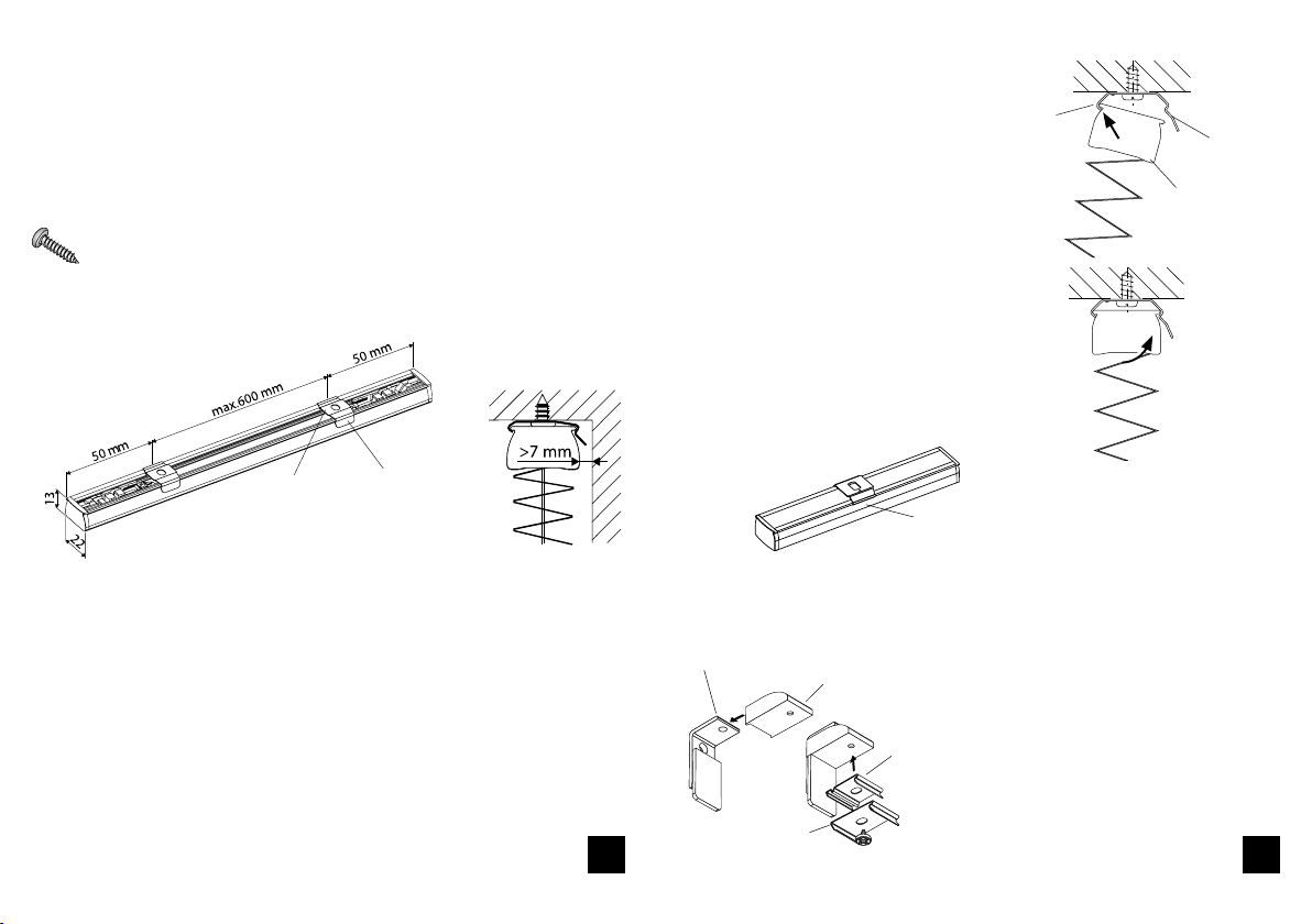
Befestigungsplättchen oder Basisteil in
Montagehilfe schieben.
Montagehilfe
Hinterlüftungsabstand 5 mm
Hinterlüftungs-
abstand 3 mm
Schienenbreite 22 mm
+5 bzw. +3 ist der gewünschte Mindestabstand zur Glasscheibe (Hinterlüftungsabstand).
recommendation:
recommandation:
Ø 2 mm
Place the assembly aid on the window bar (directly on the pane). Pre-drill and screw the xing plate.
Placer le gabarit de montage sur la baguette à verre (directement à la vitre). Amorcer et visser la plaque de
xation.
Montagehilfe auf der Glasleiste positionieren (direkt an die Glasscheibe).
Vorbohren und dann Befestigungsplättchen anschrauben.
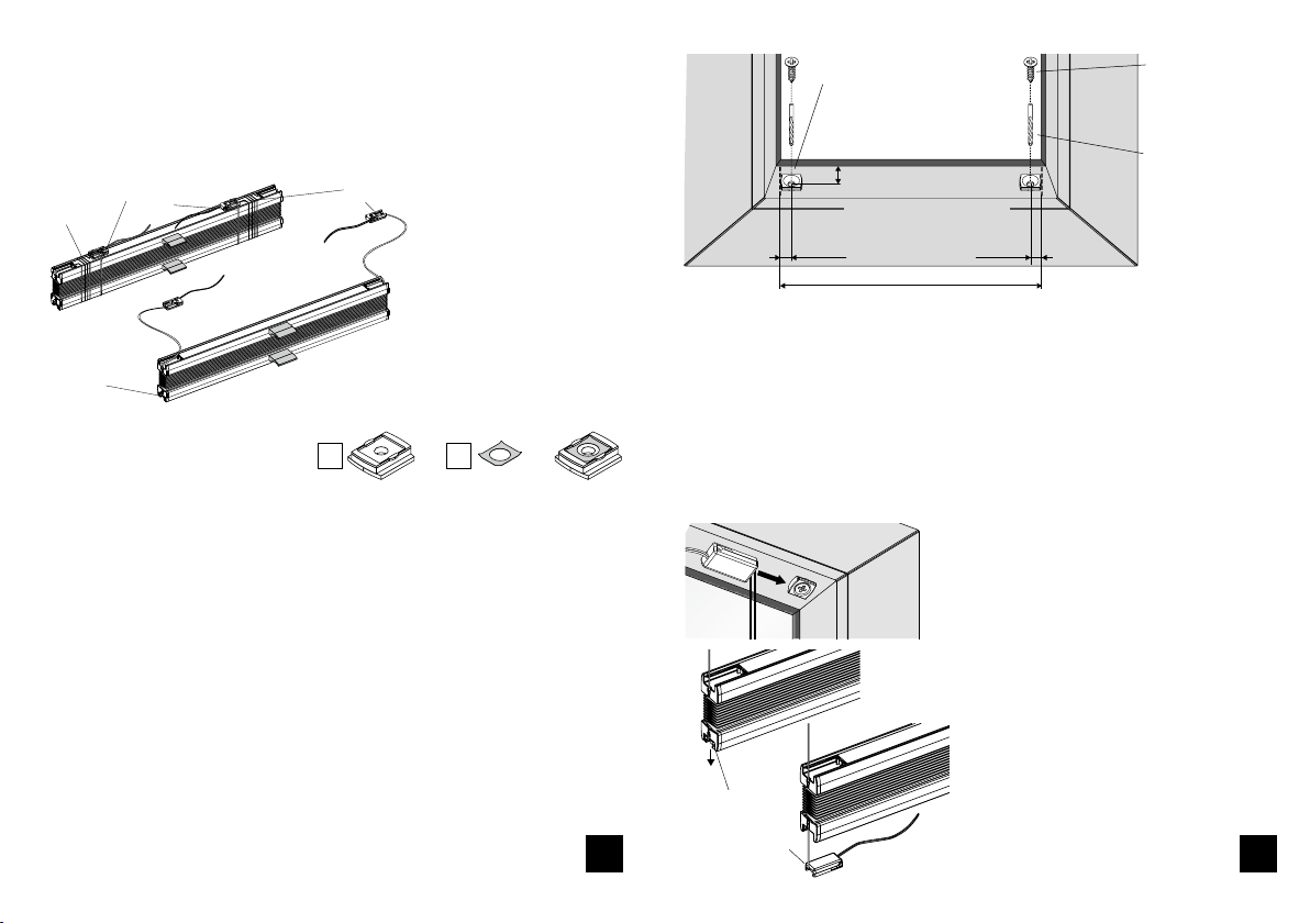
ordered width – largeur commandée
xing plate and optional
anti-twist device
plaque de xation et
plaquette anti-torsion
en option Bestellbreite
Befestigung-
splättchen
+ optional
Verdrehsicherung
Empfehlung:
Ø 2 mm
Montagehilfe
assembling aid
gabarit de montage
7
Remove the assembling aid from the xing plate.
Enlever le gabarit de montage de la plaque de xation.
Montagehilfe vom Befestigungsplättchen abziehen.
Install the xing plate by means of an assembling aid
Installer la plaque de xation à l‘aide d‘un gabarit de montage
EBefestigungsplättchen mittels Montagehilfe montieren
xing plate
plaque de xation
Befestigungsplättchen
Push the xing plate or basic part into the assembling aid.
Pousser la plaque de xation ou la pièce de base au gaba-
rit de montage.
recommendation:
recommandation:
DIN 7981
Ø 3,5 × 9,5 mm
Empfehlung:
DIN 7981
Ø 3,5 × 9,5 mm
Assembly and operating instructions
Notice de montage et mode d’emploi
Pleated blinds – Stores plissés
subject to technical change
sous réserve de modications techniques
for vertical and tilt and turn windows
pour fenêtres verticales et rotobasculantes
Tensioned types - Types tendus
Model C - Modèle C
technische Änderungen vorbehalten
08 / 2014
Plissees
für Senkrecht- und Drehkippfenster
Montage- und
Bedienungsanleitung
Achtung
Kinder können sich in den Schlingen von Schnü-
ren, Ketten oder Gurten zur Bedienung von Sicht-
und Sonnenschutzeinrichtungen verfangen oder
sich Schnüre um den Hals wickeln und sich unter
Umständen dadurch strangulieren. Schnüre,
Ketten und Gurte sind außer Reichweite von Kin-
dern zu halten, um Verwicklungen und Strangu-
lierungen zu vermeiden. Betten, Kinderbetten
und Möbel sind entfernt von Bedienungen für
Sicht- und Sonnenschutzeinrichtungen aufzu-
stellen.
entspricht EN 13120
Attention – Attention
Children can get caught in the loops of cords,
chains or straps that operate window coverings or
they can wrap cords around their necks and stran-
gle thereby. Keep cords, chains and straps out of
reach of children to avoid entanglement and stran-
gulation. Move beds, cots and furniture away from
window covering operations.
according to EN 13120 – selon EN 13120
Les enfants peuvent se prendre dans cordons, chaî-
nettes ou courroies qui actionnent les stores de
protection solaire et visuelle ou ils peuvent enrou-
ler les cordons autour leur cou et ainsi s’étrangler.
Maintenez les cordons, chaînettes et courroies hors
de portée des enfants pour éviter de s’étrangler ou
de s’emmêler. Placez les lits, berceaux et meubles à
l’écart des manipulations des stores de protection
solaire et visuelle.
Typen verspannt
ESG1, ESG2, ESG3,
ESG50
Ausführung C
1 2
Erst Aufsatz auf Wandwinkel auf-
stecken, dann Halteclip anschrauben.
Put the top part on the wall fixing bracket before
screwing the fixing clip.
Aprés avoir mis la partie supérieure sur le support
mural, visser le clip de fixation.
While xing the clip respect that they have to be mounted 50 mm from outside and with a max. distance of 600
mm.
Veuillez respecter lors de la xation des clips qu‘ils sont montés 50 mm à l’éxterieur et avec une distance maxi-
male de 600 mm.
Do not use countersunk screws for fixing. Recommendation: DIN 7981 Ø 2.9 × 16 mm (for wooden and PVC win-
dows)
N‘utiliser pas de vis à tête fraisées pour la xation. Recommandation: DIN 7981 Ø 2,9 × 16 mm (pour fenêtres en
bois ou PVC)
Advice:
The clip is preferably installed in a way that the lug is in front (visible side). If the lug shows towards the window or
pane, the clip can only be installed if the distance to the rail is at least 7 mm.
Indication:
Veuillez de préférence xer le clip ainsi que la patte se trouve devant (côté visible). Si la patte montre vers la fenêtre
ou bien la vitre, le clip peut être seulement xé si la distance au rail est au moins 7 mm.
lug
patte
Installation of the clip – Montage du clip
prole
prolé
lug
patte
Installation: Put the edge of the prole angularly into the clip (in front of the lug) and tilt it into the clip
until it clicks in.
Installation: Poser le bord du prolé angulairement au clip (en face de la patte) et tourner-le au clip
jusqu‘il s‘enclenche.
For dismantling, push the lug of the clip upwards to
remove the prole from the clip.
Pour le démontage, veuillez pousser la patte du clip
vers le haut an de retirer le prolé du clip.
Installation position: If the blind is xed on the ceiling
or wall, make sure that the package height does not
collide with the tilted or opened window sash.
Position de montage: Si le store est xé au plafond ou
au mur, faire attention que le paquet n‘entre pas en
collision avec le battant ouvert ou basculé.
xing clip „large“
clip de xation „grand“
wall xing bracket with cover cap
support mural avec cache
xing clip
„small“
clip de
xation
„petit“
top part
partie supérieure
WALL FIXATION
FIXATION MURALE
CEILING FIXATION
FIXATION PLAFOND
Lasche
Clip
Hinweis:
Clip wird vorzugsweise mit der Lasche nach vorn (Sichtseite) montiert.
Clip kann mit der Lasche zum Fenster bzw. zur Scheibe nur montiert werden,
wenn der Abstand zur Schiene min. 7 mm beträgt.
Zur Befestigung darf keine Senkkopfschraube verwendet werden.
Empfehlung: DIN 7981 Ø 2,9 × 16 mm (für Holz- oder Kunststofffenster)
Bei der Clip-Befestigung beachten, dass die Clips 50 mm von außen und mit einem
max. Abstand von 600 mm montiert werden.
Montage: Die Kante des Profils schräg in den Clip (gegenüber der Lasche) einset-
zen und dann in den Clip hinein schwenken bis es einklickt.
Clip
Profil
Lasche
„Klick“
DECKENMONTAGE
WANDMONTAGE
Clip
Zur Demontage drücken Sie die
Lasche des Clips hoch, um das Profil
aus dem Clip entnehmen zu können.
Montageposition: Bei Decken-/
Wandmontage beachten, dass die
Pakethöhe nicht mit dem gekipp-
ten oder geöffneten Fensterflügeln
kollidiert.
AClip-Montage
Halteclip„groß“
Wandwinkel mit Abdeckkappe
Aufsatz
Halteclip
„klein“
43
1 2
+ =
ÖFFNEN!
5,5 mm
Take the lower tension cord brackets out of the rail
and push them on the lower installed xing plate
until they click into place.
Prendre les supports de cordon de tension
inférieurs du rail et pousser-les sur les plaques
de xation montées en bas jusqu’à ce qu’ils
s’enclechent.
Spannschuh
unten
cord
cordon
rubber band
bande élastique
upper tension cord bracket
support de cordon de tension supérieur
OPEN!
OUVRIR!
lower tension cord
bracket
support de cordon
de tension inférieur
Remove the rubber band and unwind the cord incl. the bracket (e.g. type ESG2).
Enlever la bande élastique et dérouler le cordon incl. le support (p.ex. type ESG2).
Installation of the tension cord bracket
Fixation du support de cordon de tension
Installation of the tension cord bracket - Fixation du support de cordon de tension
Install the xing plate and the anti-twist device at the top and/or at the bottom (view from below).
Fixer la plaque de xation et la plaquette anti-torsion en option en haute et/ou en bas (vue de bas).
min. 11 mm to seal plus venti-
lation distance
au moins 11 mm jusqu‘au joint
+ distance de ventilation
ordered width
largeur commandée
xing plate and optional anti-twist
device - plaque de xation et pla-
quette anti-torsion en option
*Advice: In order to avoid glass breakage, a minimum distance to the pane has to be kept!
Recommendation: Transparent fabrics: min. 3 mm ventilation distance. Blackout fabrics: min. 5 mm ventilation
distance (special glass may, according to instructions from the manufacturer, require a bigger distance).
*Indication: Pour éviter le bris de glaces, une distance minimale à la vitre doit être respectée!
Recommandation: Tissus transparents: au moins 3 mm distance de ventilation. Tissus occultants: au moins 5 mm
distance de ventilation.(Des verres spéciaux ont éventuellement besoin des distances plus grandes en raison de
l’instruction du fabricant.)
Push the upper tension cord bracket on the above
installed xing plates until they click into place.
Pousser les supports de cordon de tension supéri-
eures sur les plaques de xation montées en haut
jusqu’à ce qu‘ ils s‘enclechent.
lower tension cord
bracket
support de cordon
de tension inférieur
5,5 mm
recommendation:
recommandation :
Ø 2 mm
recommendation:
recommandation:
DIN 7981 Ø 3,5 × 9,5 mm
Empfehlung:
DIN 7981 Ø 3,5 × 9,5 mm
Gummiband Spannschuh oben
Spannschuh
unten
Bestellbreite
Befestigungsplättchen +
optional Verdrehsicherung
min. 11 mm bis zur Dichtung
plus Hinterlüftungsabstand *
Empfehlung: Ø 2 mm
* Hinweis:
Um Glasbruchschäden zu vermeiden, muss ein Mindestabstand zur Glasscheibe ein-
gehalten werden!
Empfehlung: Transparente Stoffe: min. 3 mm Hinterlüftungsabstand. Abdunkelnde
Stoffe: min. 5 mm Hinterlüftungsabstand
(Spezialgläser benötigen aufgrund der Herstelleranweisung evtl. größere Abstände).
Die oberen Spannschuhe auf die
oben montierten Befestigungsplätt-
chen schieben, bis sie einrasten.
Die unteren Spannschuhe aus der
Schiene nehmen und auf die unten
montierten Befestigungsplättchen
schieben, bis sie einrasten.
Schnur
SPANNSCHUHMONTAGE
Befestigungsplättchen + optionalVerdrehsicherung oben und/oder unten montie-
ren (Sicht von unten).
BSpannschuhmontage
Gummiband entfernen und Schnur inkl. Spannschuh abwickeln (Beispiel: Typ ESG2).
56
C Montagemöglichkeiten
WANDBEFESTIGUNG
mit Spannschuh
Nach der Funktionskontrolle kön-
nen die überstehenden Schnüre
abgeschnitten werden.
AUSGLEICH VON AUFMASS-
UNGENAUIGKEITEN
Durch Lösen der Schrauben kann
die Schnurspannung des Plissees
verändert werden.
Ausgleichmöglichkeit max. ± 20 mm.
ARRETIERUNG
des Bedienprofils auf der Spann-
schuhbefestigung
Hinweis:
Die Änderung der Schnurspannung
muss gleichmäßig erfolgen und ist
nur vom geschulten Fachpersonal
vorzunehmen!
„Klick“
Spannschuh
Bedienungsprofil
ESG2 ESG3ESG1
Tensioned pleated blinds can be closed or opened by movement with the grip.
Stores plissés tendus peuvent être ouverts ou fermés par mouvement de la poignée.
Mounting options - Options de montage
Operation - Manipulation
wall xing bracket
support mural tension cord bracket
support de cordon de
tension
WALL FIXATION
with tension cord bracket
FIXATION MURALE
avec support de cordon de
tension
cover cap
cache
RETENTION of the operation prole on the tension
cord bracket xation.
ARRET du prolé de manipulation sur la xation
de support de cordon de tension.
tension cord bracket
support de cordon
de tension
operation prole
prolé de manipulation
Advice:
The changing of the cord tension has to occur
evenly and can only be made by qualied perso-
nnel.
Indication:
Le changement de la tension de support de cordon
de tension doit être eectué également et doit
seulement être fait par spécialistes.
Jutting out strings can be cut o after the
function check.
Le cordon en saillie peut être coupé après le
contrôle de fonctionnement.
pair of top parts
pair de parties supérieurs
BALANCING OF MEASUREMENT INACCURACIES
The cord tension of pleated blinds can be changed
by loosening the screws.
Possibility of balancing max. ± 20 mm.
COMPENSATION D‘IMPRÉCISIONS DE MESURE
La tension de cordon des stores plissés peut être
changée par un desserrage des vis.
Possibilité de compensation max. ± 20 mm.
C Montagemöglichkeiten
D Bedienung
Gespannte Plissee-Anlagen schließt bzw. öffnet man durchVerschieben des Bedi-
engriffes.
Spannschuh
Wandwinkel
Abdeckkappe
Aufsatzpaar

This manual suits for next models

3

Other Plissees Window Blind manuals

Plissees VS4 Slope User manual

Plissees

Plissees VS4 Slope User manual

Plissees DF20 User manual

Plissees

Plissees DF20 User manual

Plissees DF Comfort 20 User manual

Plissees

Plissees DF Comfort 20 User manual

Plissees VS1 User manual

Plissees

Plissees VS1 User manual

Plissees DF Comfort 20 User manual

Plissees

Plissees DF Comfort 20 User manual

Plissees DF10 User manual

Plissees

Plissees DF10 User manual

Plissees F Slope 1 User manual

Plissees

Plissees F Slope 1 User manual

Plissees EDF1 User manual

Plissees

Plissees EDF1 User manual

Plissees EDF2 User manual

Plissees

Plissees EDF2 User manual

Popular Window Blind manuals by other brands

Motion CM-09 Setup guide

Motion

Motion CM-09 Setup guide

Bali Horizontal Blinds How to install

Bali

Bali Horizontal Blinds How to install

John Lewis Sheraton Roman Blind quick start guide

John Lewis

John Lewis Sheraton Roman Blind quick start guide

Draper SHADE SP Installation & operation instructions

Draper

Draper SHADE SP Installation & operation instructions

Rollo Rieper Vario Mounting instructions

Rollo Rieper

Rollo Rieper Vario Mounting instructions

livani Day & Night Mini installation manual

livani

livani Day & Night Mini installation manual

Erfal EASE installation guide

Erfal

Erfal EASE installation guide

TOSO Shiori 25 Cord Single instruction manual

TOSO

TOSO Shiori 25 Cord Single instruction manual

SMARTWINGS Drapery Quick installation guide

SMARTWINGS

SMARTWINGS Drapery Quick installation guide

WeatherMaster Verishade XT product manual

WeatherMaster

WeatherMaster Verishade XT product manual

B&C Honeycomb installation guide

B&C

B&C Honeycomb installation guide

Inspire Rushmore Assembly, Use, Maintenance Manual

Inspire

Inspire Rushmore Assembly, Use, Maintenance Manual

Silent Gliss SG 3000 Installation and user manual

Silent Gliss

Silent Gliss SG 3000 Installation and user manual

Silent Gliss SG 1032 installation instructions

Silent Gliss

Silent Gliss SG 1032 installation instructions

HunterDouglas RB 500 Manual Installation

HunterDouglas

HunterDouglas RB 500 Manual Installation

Euro Systems Serena 170 Operation and maintenance

Euro Systems

Euro Systems Serena 170 Operation and maintenance

MV LINE EVO ZIP Instructions for assembly

MV LINE

MV LINE EVO ZIP Instructions for assembly

IKEA KADRILJ 120 instructions

IKEA

IKEA KADRILJ 120 instructions

manuals.online logo
manuals.online logoBrands
  • About & Mission
  • Contact us
  • Privacy Policy
  • Terms and Conditions

Copyright 2025 Manuals.Online. All Rights Reserved.