Plus BF-030 S Operation User manual

COPY BOARD
BF-030S
BF-030W
BF-035
SERVICE MANUAL
PLUS

CONTENTS
FEATURES ................................................................................................................................................................. 1
PRODUCT FEATURES .............................................................................................................................................. 2
SPECIFICATIONS ...................................................................................................................................................... 3
CONTROL FUNCTIONS ............................................................................................................................................. 4
MAINTENANCE/HOW TO STORE ............................................................................................................................. 5
HANDLING PRECAUTIONS....................................................................................................................................... 6
CHECK LIST OF SIMPLE FAILURES ........................................................................................................................ 6
MAIN-BOARD SETTING TABLE ................................................................................................................................ 7
OPERATION PANEL VIEWS ...................................................................................................................................... 7
ADJUSTMENT MODES .............................................................................................................................................. 8
CCD BOARD ADJUSTMENT...................................................................................................................................... 9
TROUBLESHOOTING .............................................................................................................................................. 12
DISASSEMBLY ......................................................................................................................................................... 14
PARTS LIST .............................................................................................................................................................. 19
WIRING DIAGRAM ................................................................................................................................................... 44
INTERNAL CONNECTING FUNCTION .................................................................................................................... 46

1
FEATURES
●The board size is W1300mm ×H920mm-large enough to show all the ideas that you discuss during
your meetings, without any omissions.
●Information on the large screen can be copied immediately onto a sheet of A4/Letter paper.
Those who attend a meeting can concentrate on the subject, as there is no need to waste time
jotting down notes.
●The board screen can be slid easily, and it is a simple user-friendly unit with a power cord
storage hook that comes in handy when moving the unit, a powder tray enabling easy disposal
of powder, etc.
●The BF-030S can be easily upgraded for use with your PC (with optional PC interface board)
BF-030S
BF-030W
●The board size is W1800mm ×H920mm-large enough to show all the ideas that you discuss during
your meetings, without any omissions.
●Information on the large screen can be copied immediately onto a sheet of A4/Letter paper.
Those who attend a meeting can concentrate on the subject, as there is no need to waste time
jotting down notes.
●The board screen can be slid easily, and, the powder tray is designed for easy disposal of
powder.
●The BF-030W can be easily upgraded for use with your PC (with optional PC interface board)
BF-035
●The 1300mm(51")W ×920mm(36")H writing surface provides ample space to record all information
discussed during meetings.
●Since the unit can instantly print an A4/Letter sized copy of what is on the panel, your audience
is freed from distracting note taking and can fully concentrate on the subject at hand.
●This unit has been designed with 4 writing panels (page 1-4) which can be printed out. The 5th
panel is designed for use as a projection screen only.
●The BF-035 can be easily upgraded for use with your PC (with optional PC interface board)
CAUTION: Please do not write on the 5th panel (projection screen) as it is non-erasable and will
stain.

2
PRODUCT FEATURES
REAR
FRONT
Tray
Printer
Caster
T-shaped stand
Expansion slot
(for optional upgrades)
Optional accessory sold separately:
PC interface board - to enable down-
loading of board information from the
BF-030S/W/035 to the PC
()
Board screen 50mm ×50mm
gridded surface area
Operation panel
Printer cover
T-shaped stand

3
SPECIFICATIONS
Item BF-030S
Board surface size W1300 ×H920 mm (51-3/16 ×36 inch)
Effective reading size
W1240 ×H880 mm (48-7/8 ×34-3/4 inch)
Number of pages
Screen driving method
Panel driving method
Grid
Writing instruments
Reading method
Recording method
Recording density
Recording paper
Size of recording paper
Recording color
Recording speed 1-surface copy: 11 sec/copy
2-surfaces reduced copy: 22 sec/copy
Operating conditions
Power source
Power consumption
Outer dimensions W1470 ×D600 ×H1885 mm
(57-7/8 ×23-5/8 ×74-2/8 inch)
Weight 41 kg
Others Consumables
Optional
Accessory
BF-030W
W1800 ×H920 mm (71 ×36 inch)
W1740 ×H880 mm (68-1/2 ×34-3/4 inch)
1-surface copy: 15 sec/copy
60W at stand-by, 120W at operation
W1970 ×D600 ×H1885 mm
(77-4/8 ×23-5/8 ×74-2/8 inch)
46 kg
BF-035
W1300 ×H920 mm (51-3/16 ×36 inch)
W1240 ×H800 mm (48-7/8 ×34-3/4 inch)
5 pages (4 pages can be copied)
The 5th page is a projection screen
1240 (50") ×880 (35")
Bi-directional scrolling method
50mm sq./2" sq.
1-surface copy: 11 sec/copy
W1470 ×D600 ×H1885 mm
(57-7/8 ×23-5/8 ×74-2/8 inch)
45 kg
Placing this unit next to equipment or buildings (such as broadcasting stations) where strong RF interference is generated may sometimes
cause printing to become blurred or disordered when copies are made. This does not indicate a breakdown or problem in this unit.
*Specifications are subject to change without notice for improvement.
2 pages
One direction endless drive
50mm squares
CCD sensor, plane scanning
Thermal printing with thermal head
8 dot/mm
Special thermal sensitive paper
(30 m roll)
A4 size (210 ×297mm)
Letter size (8-1/2 ×11 inch)
Black
Temperature: 5-35˚C
Humidity: 30-85%
(Without dew condensation)
North America 120V AC 60Hz
Europe 230V AC 50Hz
Asia/Oceania 220-240V AC 50Hz
Central South America
Middle/Near East Respective rated local voltage/frequency
(110V, 120V, 220-240V)
Special thermal recording paper (30-m roll/98FT)
Special markers
Special eraser
PC interface kit
Special markers (black/red/blue)

4
CONTROL FUNCTIONS
A
Opening button ........... Press this button to open the printer hatch when
replacing the thermal paper.
B
Power switch .............. Press "I" to turn ON the power when starting
machine operation.
C
Power lamp ................. Press the switch, and the green lamp will
blink on and off. The lamp will stay lit (green)
when the read sensor inside the machine is
ready for operation.
D
Paper warning lamp ... When the thermal paper has run out, the
red lamp will light. Load new recording
paper.
E
One-surface copy key .. This is used when one page of the screen
is copied onto A4 paper. The machine
produces a copy at a reduced scale of the
same length and breadth.
PLUSBOARDFAX BF-030S
POWER
OPEN
A B C D FGHI
PAGE
1
2
3
4
5
E
REPEAT
COPY PC STOP
FEED
PAPEROUT
POWERON
F
Two-surface reductia .. This is used when copying two pages of the
screen at a reduced size onto A4 paper. At
this time, the copy is reduced horizontally.
G
Repeat key .................. For use with optional PC interface kit.
H
PC COPY key .............. For use with optional PC interface kit.
I
Feed/stop key ............. This is used when the screen slides to the left.
Pressing this key advances the screen by one
page and then automatically stops.
Pressing the key while the board screen is being
moved stops it immediately. This can also be
used when paper has run out and must be
refilled.
If this key is pressed during the copying
operation, the copying performance ends and
the printer stops.
BF-030S OPERATION PANEL
BF-030W OPERATION PANEL
A
Opening button .......... Press this button to open the printer hatch
when replacing the thermal paper.
B
Power switch .............. Press "I" to turn ON the power when starting
machine operation.
C
Power lamp ................. Press the switch, and the green lamp will
blink on and off. The lamp will stay lit (green)
when the read sensor inside the machine is
ready for operation.
D
Paper warning lamp ... When the thermal paper has run out, the
red lamp will light. Load new recording
paper.
E
A4 reduction copy key ..
This is used when copying one page of
the screen at a reduced size onto A4
paper. At this time, the copy is reduced
horizontally.
PLUSBOARDFAX
BF-030W
POWER
OPEN A4 L
A B C D FGHI
E
REPEAT
COPY PC STOP
FEED
POWERON
PAPEROUT
F
A4-L copy key ............. This is used when one page of the screen
is copied onto A4-L paper. The machine
produces a copy at a reduced scale of the
same length and breadth.
G
Repeat key .................. For use with optional PC interface kit.
H
PC COPY key .............. For use with optional PC interface kit.
I
Feed/stop key ............. This is used when the screen slides to the left.
Pressing this key advances the screen by
one page and then automatically stops.
Pressing the key while the board screen is
being moved stops it immediately. This can
also be used when paper has run out and
must be refilled.
If this key is pressed during the copying
operation, the copying performance ends
and the printer stops.
Two-surface reduction
copy key

5
A
Opening button .......... Press this button to open the printer hatch
when replacing the thermal paper.
B
Power switch .............. Press "I" to turn ON the power when starting
machine operation.
C
Power lamp ................. Press the switch, and the green lamp will
blink on and off. The lamp will stay lit (green)
when the read sensor inside the machine is
ready for operation.
D
Paper warning lamp ... When the thermal paper has run out, the
red lamp will light. Load new recording
paper.
E
Page lamp ................... These lamps indicate which panel is on
display presently. The blinking green lamp
indicates the page to which the unit is turning
to. (The SCREEN is indicated by an orange
lamp.)
PLUSBOARDFAX BF-035
POWER
POWERON
PAPEROUT
OPEN PAGE-L COPY PC SCREEN
A B C D
PAGE-R
J
FGHIK
PAGE
1
2
3
4
SCREEN
E
REPEAT
BF-035 OPERATION PANEL
F
PAGE-L key ................ Press this key to slide the panel to the left. (Press
once for each panel you wish to turn to.)
G
Copy key ..................... The panel displayed will be printed out on
A4/Letter sized thermal paper. The print out
will be reduced proportionally to the original
information on the panel.
H
Repeat key .................. You can make another copy of the last panel
by pressing this key. The panel will not move
while the unit is reprinting.
I
PC COPY key .............. For use with optional PC interface kit.
J
PAGE-R key ................ Press this key to slide the panel to the right.
(Press once for each panel you wish to turn to.)
K
Screen key .................. Press this key to move to the fifth panel.
The unit will not move to the fifth panel with
the PAGE-L key. Press the SCREEN key
again to return to page 1.
MAINTENANCE/HOW TO STORE
Carry out the following maintenance procedures periodically to ensure high quality copying performance at all times.
(1) Cleaning of the surface ....... (BF-030S/W only)
When the surface gets stained, wipe it off with a slightly damp cloth. Also, if the stain is particularly stubborn, use
a solution of water-thinned neutral detergent to wipe it off. Do not start using the machine until the sheet has
completely dried.
(2) Cleaning of pages 1-4 ......... (BF-035 only)
When the surface gets stained, wipe it off with a slightly damp cloth. Also, if the stain is particularly stubborn, use
a solution of water-thinned neutral detergent to clean. Do not start using the machine until the panel has completely
dried.
(3) Cleaning of projection screen (page 5) .......... (BF-035 only)
Wipe ordinary stains in the same manner as shown in (1).
If something is written on this screen by accident, wipe it off with a cloth dampened with a neutral detergent.
(4) Cleaning of tray and decorative frame
Wipe away any dirt or residue left by the markers in the tray and the decorative frame with a slightly damp cloth.

6
HANDLING PRECAUTIONS
<FOR SAFE USE>
1. Avoid placing the machine in hot spots where it is exposed to direct sunlight or where an air conditioning duct.
2. When using sticky tape on the surface of the board screen, do not leave it on for a long time. Moreover, after
removing it, wipe the screen clean. Do not hit or pierce the board screen with any hard or sharp objects.
3. Do not leave writing or marks on the board screen for a long time since it sometimes become difficult to erase
(BF-030S/W only).
4. Be careful not to stain the joints of the board screen as there have been very rare cases where such stains have
been copied. ...... (BF-030S/W only)
5. Do not leave writing or marks on pages 1-4 for a long time since it may become difficult to erase. ..... (BF-035 only)
6. As thinner, benzine, alcohol, etc., may discolor or mark the main unit and the board screen, never use such
chemicals when cleaning. (BF-030S/W only)
7. As thinner, benzine, alcohol, etc., may discolor or mark the main unit and the panels, (1-4 page) never use such
chemicals when cleaning. ........ (BF-035 only)
8. Use only the correct type of thermal paper.
9. When replacing recording paper, do not place any objects on the open printer cover or do not put your elbows on it.
10. After use, make sure to turn OFF the power switch. In addition, when it is not to be used for a long time, make
certain that the plug of the power cord is pulled out form the outlet.
11. Always use the correct type of marker. Be careful not to use other markers as the sheet may be damaged or, in
some cases, the ink may be difficult to remove.
12. Write within an area of a size that can be easily read.
When storing thermal recording paper, avoid the following places. This is important because storage in such
places may cause color development or discoloration.
(1) Places where the paper is exposed to direct sunlight.
(2) Places where the paper is exposed to temperatures of more than 35˚C (95˚F) and humidity of 85% or over.
(3) Places adjacent to alcohol, thinner, benzine, ammonia, etc.
<BEFORE ASKING FOR A REPAIR SERVICE>
CONDITIONS CHECKPOINTS
∗If no satisfactory result can be achieved even after the above, contact the suppliers or our company.
When the power fails
When pressing copy key does not result in copying
Although printer is functioning, nothing is copied on
recording paper
When characters written on board screen cannot be
rubbed out even by the use of an eraser
When characters written on the panel cannot be erased
even using an eraser
When copy is dirty
30mm 30mm
20mm
20mm
Check if power cord is pulled out of outlet.
Check if paper warning lamp (red) is lit.
Check if winding direction of recording paper is set on
reverse. (No copying is made on back of recording paper)
Check if any marker except the correct type has been used.
Wipe off with a damp cloth or neutral detergent.
If something is written on page 5 by accident, wipe it off
with a cloth dampened with neutral detergent. Check if any
marker except the correct type has been used to write on
pages 1-4. Wipe off with a damp cloth or neutral detergent.
Check for ink residue on the screen. If it is stained, wipe
off carefully with a soft damp cloth.
CHECK LIST OF SIMPLE FAILURES
13. When moving this machine, turn OFF the caster lock switches, hold both the right and the left sides of the main
unit firmly, and avoid any sudden jolts or shocks.

7
MAIN-BOARD SETTING TABLE
1. MAIN-board
1
Sections marked # are set with shorting pins.
2. MAIN-board
2
✽Set with solder shorts.
J7: BF-030/035 (PC) series
3. PC board (reference)
✽Set on the BF main unit the PC board is connected to
J1: BF-030S/W (PC)
J2: BF-035S (PC)
Model Type Switch Jumper setting Remarks
panel J3 J4 J5 J6
2 surfaces/standard/A4 1)
BF-030S 2 surfaces/standard/letter #
2 surfaces/wide/A4 3) #
BF-030W 2 surfaces/wide/letter # #
5 surfaces/standard/A4 5) #
BF-035S 5 surfaces/standard/letter # #
OPERATION PANEL VIEWS
1. SWITCH PANEL VIEW (BF-030S)
2. SWITCH PANEL VIEW (BF-030W)
3. SWITCH PANEL VIEW (BF-035)
FEED
STOP
P C
REPEAT
COPY
POWER ON
PAPER OUT
POWER
FEED
STOP
P C
REPEAT
COPY L
A4
POWER ON
PAPER OUT
POWER
FEED
P C PAGE–R
REPEAT
COPY
POWER ON
PAPER OUT PAGE–L
POWER
SCREEN
1
2
3
4
SW1 2 3 4 5
SW1 2 3 4 5
SW1 2 3 4 5 6

8
ADJUSTMENT MODES
There are the following methods for entering each mode.
(1) Adjustment 1: Switch on the power while holding down SW5.
(2) Adjustment 2: Switch on the power while holding down SW1 and SW4.
To end an adjustment mode, switch off the power and switch it back on without holding down any of the keys. (Test
mode continues until the power is switched off.)
Adjustment mode specifications
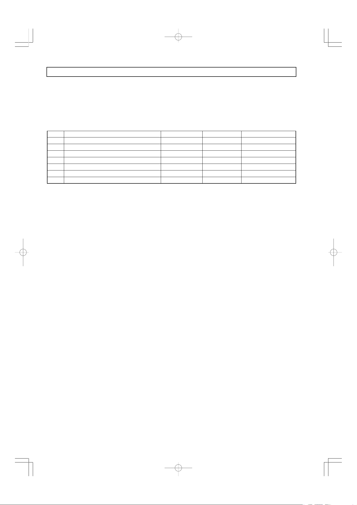
No. Function summary Operation method Adjustment 1/2/3 Remarks
1 Test pattern printing Press SW3. 1 Both 2-surface/5-surface
2 Arbitrary sheet feed Press SW1/SWS5. 1 5-surface only
3 Continuous sheet feed (1 surface ↔5 surface) Press SW1. 2 Both 2-surface/5-surface
4 12.5% continuous printing Press SW2. 2 Both 2-surface/5-surface
5 20% continuous printing Press SW3. 2 Both 2-surface/5-surface
6 Test pattern printing Press SW4. 2 Both 2-surface/5-surface
7 Continuous copying Press SW5. 2 Both 2-surface/5-surface
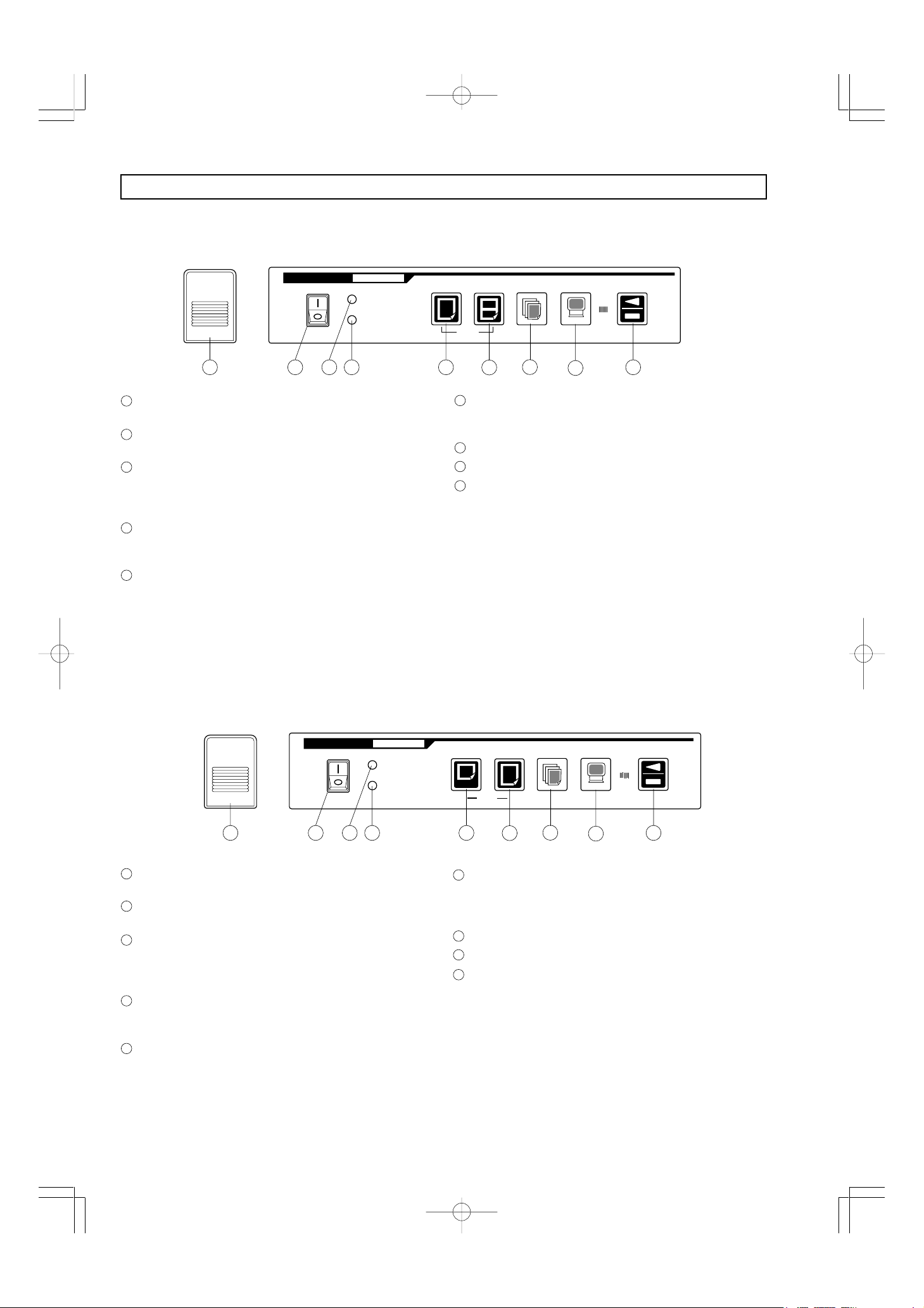
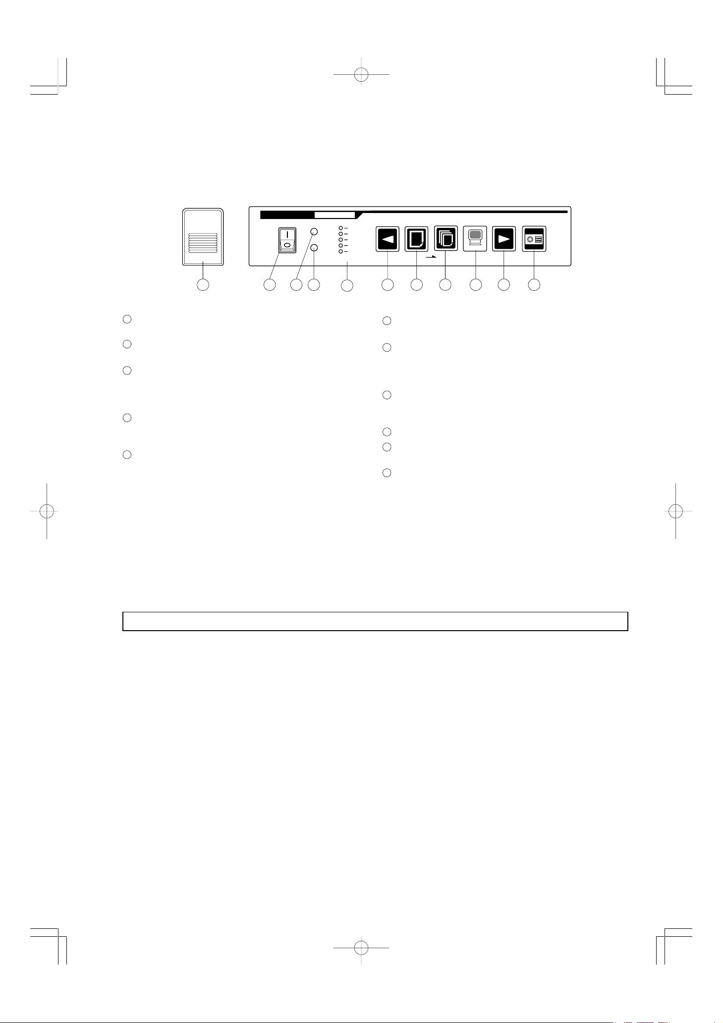
✽From the left side of the operation panel, the switches are SW1 - SW6.
✽For the 5-surface model, in Adjustment 1 mode, the COPY/STOP key is for normal copy/copy stop processing, but
sheet stretching/rewinding is not carried out.
1. Test pattern printing
Pressing SW3 prints the test pattern shown in the print
sample (same as for BF-030).
Each time SW3 is pressed, the printing is repeated.
The STOP key is enabled.
2. Arbitrary sheet feed (5-surface only)
(1)Pressing the L-FEED/R-FEED key alone feeds the
sheet about 1 cm left/right (with the motor driven at
low speed).
If you hold the key down for longer than 0.5 second,
the sheet is fed continuously left/right until you release
the key.
(2)If you press the R-FEED key while holding down the
STOP key the sheet latch is released/set. When the
sheet latch is set, all the LEDs except the paper end
LED lights up (to show that the paper tube can be turned
manually).
<Notes>
. These modes do not manage the pages with the CPU,
so be careful when working near the edge of the sheet.
. The sheet is not stretched after the sheet feed
operations.
. When the sheet latch is set, the sheet is not fed other
than for 1-cm feeds (Item 1).
. When the sheet is fed at positions where the paper
tube is thick, the movement distance decreases due
to insufficient torque.
. The fluorescent lamp is always lit. (It is not
extinguished even if the gain check result is NG.)
3. Continuous sheet feed
After a power-on reset, pressing SW1 feeds the sheet
continuously.
The interval between surfaces is about 2 seconds. For
the 5-surface model, the sheet is stretched each time
a surface is fed.
Continuous feed is an unending loop that continues
until the power is switched off. (The STOP key is
disabled.)
4. 12.5% continuous printing
Pressing SW2 continuously prints a black belt (about
10 mm) diagonal line at intervals about 12.5% of the
paper width.
The interval for each sheet is about 2 seconds.
5. Pressing SW2 continuously prints the same
as for Item 4, but with intervals of 20%.
6. Test pattern printing
Pressing SW4 prints the test pattern. The STOP key
is disabled.
7. Continuous copying
Switching on the power in Adjustment Mode 2 and
pressing SW5 automatically starts continuous copying
operations.
The interval between surfaces is 3 seconds.
For a 5-surface model, from Surface 1 to Surface 4 is
copied and after these four surfaces have been copied,
the sheet is returned non-stop to Surface 1 and
consecutive copying resumes.
Continuous feed is an unending loop that continues
until the power is switched off. (The STOP key is
disabled.)
Hidden mode
For a 5-surface model, if the power is switched on with
SW5 and SW6 held down, the sheet latch is released.

9
CCD BOARD ADJUSTMENT
1. Initialization
1) Range setting of oscilloscope
CH1 100 mV/div. (for 10:1 probe)
CH2 20 mV/div. (for 10:1 probe)
Time base 0.5 ms
Coupling DC
2) Connect the probe to the test pin on the main board.
CH1 J9
CH2 J1
CH3 J10
GND J2
The trigger source for Channel 3 coupling is AC.
3) GND position adjustment (See the figure on the right.)
Immediately after the oscilloscope power is switched
on, the ground position fluctuates easily, so
occasionally check that the Channel 1 coupling is
aligned to ground.
2. Temporarily Fixing of Lens Unit
•Fix SC(1) temporarily by the adjustment of the back
plate and end face.
•Fix SC(2) temporarily in the horizontal state.
•Fix SC(3) temporarily in the center position.
•Fix SC(4) temporarily with the CCD board put in the
vertical state.
•Fix SC(5) (square screw) temporarily in the position
where the lens barrel is 2 mm forward from the holder.
•Fix the shade temporarily in the position where it was
brought near the sheet.
✽Adjustment mode
Switch on the power while holding down the STOP key
(BF030S/W) or the PAGE-R key (BF-035).
3. Optical Axis Alignment
1) Loosen SC(2) and shake the board forward and
backward until the waveform on the oscilloscope is
as shown in the figure. (Saturation)
3.8 V or more
3 ms or more (6 divisions)
0V
SC1
SC2
SC5
CCDboard SC4 SC3
0V

10
2) Slide the lens shade to adjust the amount of light so
that the aperture peak waveform is flat, then secure
the lens shade in place. (See the figure on the right.)
Adjustment range (limit values) 2.6-3.4 V
Adjustment standard 3.3 V
Be careful not to exceed the top limit of 3.8 V.
4. Focus Adjustment
1) As shown in the figure, enter a pattern, obtained when
50 mm square was divided into 36 equal parts, in the
red vertical line and the upper and lower ruled lines
of two lines of 3 mm in width.
2) Confirm that the CCD waveform is 2.6 V or more.
•Search the lowest falling position of the waveform
while moving the lens barrel from the fluorescent
lamp to the CCD board and fix the lens barrel in the
corresponding position.
•The falling value of the black level should be less
than 2.3 V from the GND level as the reference
value.
5. Reading Width Adjustment
1) Adjustment reference value: 890 to 910 mm
2) Reading width adjustment
•Loosen SC(3) and adjust so that the reference line in the
figure is uniformly copied in the vertical direction while
shaking the lens unit upward and downward. After that,
fix SC(3).
•If the reading value is higher than the reference value,
loosen SC(1) and move the whole lens unit to the right. If
it is lower than the reference value, mode the whole lens
unit to the left.
Red vertical line
Ruled line
50 x 50 mm
Pattern with 36
equal divisions
0V
3.3V
10mm
φ10
10mm
Ruled line
850 910
870
890
0V
3.3V

11
6. Optical axis alignment
•As shown in the figure, enter a mark on the block
vertical line and at a point 71 mm away from the black
line.
•Move the sheet until the mark moves to the left edge.
(The vertical line is reflected in the center of the mirror.)
•Move SCs 2 and 4 to make the waveform shown in
the figure.
7. Shade adjustment
•Switch the power off, then switch it back on in normal
mode.
•Make two waveforms appear on the oscilloscope.
•Set the oscilloscope mode to Chop.
●Channel 1 The gain is automatically adjusted and
the waveform amplitude becomes
larger.
●Channel 2 The actual waveform (The waveform
in the figure has a different ground level
from Channel 1.)
8. Print check
•If the waveform is tilted, flatten it with the shade. (Align
to 3.0-3.5 V.)
•Tighten the SCs.
•Check that the print patterns are copied within the
standards.
Reading width: 890-910 mm
Focus: 2 lines with widths of 3 mm must be
printed.
Also, the measurement grid must not
be broken.
Others: After copying one surface, check that
there are no dark lines on the copy.
71mm
0V
0V
CH1
CH2
Cautions for Maintenance
•In principle, when lens units and CCD boards are
replaced in the field, use a factory-adjusted unit (lens
unit + CCD board).
•Procedure for adjustment after replacement
(1) Temporarily secure the adjusted unit with SC1.
(2) Check the light shaft alignment.
(3) After adjusting the reading width, secure the unit
with SC1.
(4) Check printing.

12
TROUBLESHOOTING
Item Trouble Cause Correction
1
2
3
4
5
6
7
The power will not turn on and no
operation is available. (POWER-ON
LED will not light.)
BOARDFAX operates but POWER-
ON LED will not light.
POWER-ON LED lights, but operation
is unavailable.
POWER-ON LED continuously blinks
on and off.
PAPER-OUT LED will not light.
PAPER-OUT LED continuously lights.
Abnormal paper feeding to printer
<Incorrect paper feeding/abnormal
sound>
1. Check the breaker.
2. Change the power cable.
3. After checking the cause of fuse
blowing, change the fuse.
4. Change the harness and insert the
connector again.
5. Change the main switch assy.
6. Change POWER-BOARD.
7. Change MAIN-BOARD.
8. Change SUB-BOARD.
1. Change the switchboard assy.
1. Change POWER-BOARD.
2. Change MAIN-BOARD.
3. Change SUB-BOARD0
4. Change switchboard assy.
5. Change the harness and insert the
connector again.
1. Insert the fluorescent lamp again or
change the fluorescent lamp.
2. Change the harness and insert the
connector again.
3. Change POWER-BOARD.
4. Change MAIN-BOARD.
1. Change the switchboard assy.
2. Change the paper switch assy.
3. Change SUB-BOARD.
4. Change the switchboard assy, or
insert the connector again.
5. Adjust the mounting position.
1. Change the paper switch assy.
2. Change SUB-BOARD.
3. Adjust the mounting position.
1. Change the printer motor.
2. Adjust the motor mounting position,
and change respective gears.
3. Change the harness, and insert the
connector again.
4. Change SUB-BOARD.
5. Change MAIN-BOARD.
6. Change the platen roller.
7. Mount them again for adjustment.
8. Change/stick again the PET tape.
9. Replace the paper with the
specified paper.
1. Power is not reaching the outlet.
2. Power cable defect
3. Blown fuse
4. Disconnection of each harness and
poor connector contact
5. Main switch defect
6. POWER-BOARD defect
7. MAIN-BOARD defect
8. SUB-BOARD defect
1. POWER-ON LED defect
1. POWER-BOARD defect
2. MAIN-BOARD defect
3. SUB-BOARD defect
4. Switchboard defect
5. Disconnection of each harness and
poor connector contact
1. The fluorescent lamp will not light.
2. Disconnection of CCD and lamp
harness, as well as poor connector
contact
3. POWER-BOARD defect
4. MAIN-BOARD defect
1. PAPER-OUT LED defect
2. Paper switch defect
3. SUB-BOARD defect
4. Disconnection of harness and poor
connector contact
5. Slipped mounting position
1. Paper switch defect
2. SUB-BOARD defect
3. Slipped mounting position
1. Printer motor defect
2. Poor engagement between the
motor gear, intermediate gear, and
platen gear, or broken gear teeth
3. Disconnection of harness or poor
connector contact
4. SUB-BOARD defect
5. MAIN-BOARD defect
6. Change of platen roller dia.
With the passage of time
7. Excessive play between the
thermal head and platen roller
8. Peeling of PET tape
9. Paper is not the specified paper.

13
Item Trouble Cause Correction
8
9
10
11
12
13
14
15
Sheet sliding anomaly <Poor sliding
operation/abnormal sound>
Copying color is too light.
Color is light as a whole.
Dots missing for all-white copy
Totally black copy & black lines/points
Copy printing horizontal jam
Laterally elongated copied characters
Repeat printing not possible
BF-030S/W
(when PC interface board mounted)
BF-035
1. Sheet motor defect
2. Poor adjustment of timing belt
tension
3. Disconnection of harness and poor
connector contact
4. Insufficient grease in sliding section
(tension/bearing section)
5. SUB-BOARD defect
6. MAIN-BOARD defect
7. Plunger defect
8. Sensor board soiled, defect
1. Poor lighting of fluorescent lamp
2. Poor head contact as a whole
3. Saturation of CCD waveforms
4. MAIN-BOARD defect
1. Poor lighting of fluorescent lamp
2. Poor head contact as a whole
3. Saturation of CCD waveforms
4. MAIN-BOARD defect
1. Harness cut line or connector
contact defect
2. CCD waveform saturated
3. Thermal head defect
4. MAIN-BOARD defect
5. SUB-BOARD defect
6. CCD lens condensation
1. Poor CCD waveform adjustment
2. Slipped optical axis
3. Out-of-focus
4. Deformation of slit stiffener
5. Dirty mirror surface
6. Dirty CCD lens surface
7. Dirty fluorescent lamp
8. MAIN-BOARD defect
9. SUB-BOARD defect
10.
CCD-BOARD detect
1. Printer paper feed abnormality
1. Sheet feeding defect
1. PC interface board jumper setting
incorrect
2. Connector contact defect
3. PC interface board defect
1. MAIN-BOARD defect
2. PC interface board jumper setting
incorrect (only when interface board
mounted)
1. Change the sheet motor.
2. Adjust the motor mounting position
and change the belt.
3. Change the harness, and insert the
connedtor again.
4. Apply grease to respective sliding
sections.
5. Change SUB-BOARD.
6. Change MAIN-BOARD.
7. Change the plunger.
8. Clean the sensor board and replace
if necessary.
1. Change the fluorescent lamp.
2. Adjust the head contact.
3. Adjust the lens shade.
4. Change MAIN-BOARD.
1. Change the fluorescent lamp.
2. Adjust the head contact.
3. Adjust the lens shade.
4. Change MAIN-BOARD.
1. Re-insert the connector; replace the
harness if necessary.
2. Adjust the lens shade.
3. Change the thermal head.
4. Change the MAIN-BOARD.
5. Change the SUB-BOARD.
6. Switch on the power and wait 30
minutes.
1. Readjust the CCD waveform.
2. Readjust the elevation angle of the
lens.
Readjust the lens shade.
3. Readjust the focus.
4. Correct the shape.
5. Clean and change defective parts.
6. Clean the CCD lens and replace if
necessary.
7. Clean the fluorescent lamp and
replace if necessary.
8. Change MAIN-BOARD.
9. Change SUB-BOARD.
10.
Change CCD-BOARD.
1. Follow the preceding item 7.
1. Follow the preceding item 8.
1. Adjust and reset the PC interface
board jumper setting (J1).
2. Re-insert the PC interface board.
3. Change the PC interface board.
1. Change the MAIN-BOARD.
2. Adjust and reset the PC interface
board jumper setting (J2).

14
DISASSEMBLY
1.Board Main Unit Disassembly
1) Remove the frame cover unit.
•Remove the two screws [M] and two screws [U]
(three screws for 030).
•Remove the main harness and the power relay
harness.
•Remove the frame cover unit.
2) Remove the back panel.
•Remove the ten screws [T] and remove back panel
corner B.
•Slide the back panel and remove it.
3) Remove the sheet frame unit (BF-030S/W)
•Remove the four screws [U].
•Remove the sheet motor connector.
•Remove the sheet unit from the sheet from hangar.
4) Remove the sheet frame unit (BF-035)
•Remove the rear side screw [D].
•Remove the board motor solenoid harness from the
main board and remove the cable.
•Remove the four screws [U].
•Remove the sheet unit from the sheet from hangar.
Decorative
frame
Back panel
Back panel
corner B
Main
unit
Sheet unit
Main
unit
Sheet unit
fixing screw
Sheet paper tube
Roller bearing screw
2.Removing the Sheet
BF-030S/W
•Lock the top and bottom slide bases.
•Move the sheet to the top and remove it from the
sheet frame.
•When mounting the sheet, place it against the roller
flange and mount slowly.
(Be careful not to scratch the sheet.)

15
3.Removing Parts from the Sheet Unit
BF-030S/W
•Remove the two sheets [H] and remove the sheet
motor.
BF-035
Solenoid
•Remove the harness wire bundle.
•Remove the two screws [A] and remove the
solenoid.
Servo motor
•Remove the harness wire bundle.
•Remove the four screws [N] and remove the motor.
*During installation, be careful about the motor belt
tension.
BF-035
•Remove the two screws [T] and remove both the
top and bottom sheet guides.
•Remove the four screws [B] and remove both
angles.
•Remove the two screws [G] and release the lever
plate.
•Remove the sheet paper tube on one side and wind
up the sheet.
•Remove the other sheet paper tube.
Fixing screw
Sheet guide (upper)
Sheet guide (lower)
Spool
Flange hub
Paper tube
pressure knob
Roller bearing
fixing angle
Adjustment
screw F=500g
L=7〜8mm
Plunger solenoid
Plunger spring
Plunger hook
Long
belt
Pulley
Board motor belt adjustment

16
4.Removing Internal Parts
Remove the main board.
•Remove the harnesses connected to the main
board.
•Restrain the locking card spacer and remove the
main board.
Remove the power board.
•Remove the power supply relay harness, the
secondary side power supply harness, and the lamp
harness.
•Remove the four screws [H].
Remove the CCD board.
•Remove the cable ties around the CCD board.
•Remove the two screws [I] and remove the CCD
board together with the lens holder.
Remove the fluorescent lamp.
•Loosen the two screws [J] and remove both the top
and bottom auxiliary mirror plates.
•Turn the fluorescent lamp and remove it to the front.
5.Printer Disassembly
1) Remove the printer unit from the frame cover.
•Remove the four screws [O] and remove the printer
unit from the frame cover.
2) Remove the printer rear cover.
•Remove the four screws [C] and the nine screws
[S].
•Remove the power supply cord from the main switch
and remove the rear cover.
3) Remove the switch panel and switch board.
•Remove the switch board harness from the sub-
board.
•Remove the cable tie.
•Remove the four hooks from the printer cover and
remove the switch panel.
•Remove the four screws [Q] and remove the switch
board.
4) Remove the sub-board paper switch
•Remove the harnesses connected to the sub-board.
•Remove the four screws [Q] and remove the sub-
board.
•Remove the two screws [P] and remove the paper
switch.
5) Remove the front cover and platen roller.
•Remove the two front cover springs.
•Remove the two hinge plate L and R E rings [c].
•Remove the four screws [R] and remove the front
cover.
•Remove the platen roller from the hinge plate.

17
6) Remove the printer frame.
•Remove the two screws [R].
•Remove the printer frame from the printer cover.
7) Remove the printer motor.
•Remove the two screws [B] and remove the printer
motor.
8) Remove the thermal head.
•Remove the two control harnesses for the thermal
head.
•Remove the screw [K] and the head fastening collar.
•Remove the head fastening screw and remove the
thermal head installation base.
•Remove the two screws [F] and remove the thermal
head from the installation base.
Sub-board
Printer frame
Hinge plate (R)
Front cover
Printer rear cover
AC cord
Switch panel

18
Type PARTS NO. Specifications Surface Processing NOTES
SCREW A 951126510 M2.6 ×5 Round head MFZn I-C 035 only
SCREW B 951230610 M3 ×6 Bind MFZn I-C
SCREW C 951240620 M4 ×6 Bind MFZn I-C
SCREW D 951244510 M4 ×45 Bind MFZn I-C 035 only
SCREW E 951430630 M3 ×6 Slotted head MFNi- I
SCREW F 952130510 M3 ×5 2-point type MFZn I-C
SCREW G 952331010 M3 ×12 2-point type Round head MFZn I-C 035 only
SCREW H 952530610 M3 ×6 3-point type MFZn I-C
SCREW I 952530810 M3 ×8 3-point type MFZn I-C
SCREW J 952531010 M3 ×10 3-point type MFZn I-C
SCREW K 952532510 M3 ×25 3-point type MFZn I-C
SCREW L 952540610 M4 ×6 3-point type MFZn I-C
SCREW M 952541210 M4 ×12 3-point type MFZn I-C
SCREW N 952541510 M4 ×15 3-point type MFZn I-C 035 only
SCREW O 953141010 M4 ×10 P Tapping Round hesd MFZn I-C
SCREW P 953226610 M2.6 ×6 P Tapping Bind MFZn I-C
SCREW Q 953230610 M3 ×6 P Tapping Bind MFZn I-C
SCREW R 953230810 M3 ×8 P Tapping Bind MFZn I-C
SCREW S 953240820 M4 ×8 P Tapping Bind MFZn
SCREW T 953630820 M3 ×8 S Tapping Bind MFZn I-C
SCREW U 953640810 M4 ×8 S Tapping Bind MFZn I-C
SCREW V 954430880 M3 ×8 Allen stop bolt Black
E RING a 958120020 ME-RING ø2 MFZn I-C 035 only
E RING b 958130020 ME-RING ø3 MFZn I-C 035 only
E RING c 958140020 ME-RING ø4 MFZn I-C
E RING d 958160020 ME-RING ø6 MFZn I-C 035 only
SPRING PIN e 956625600 Spring pin ø2.5 ×6 035 only
SPRING PIN f 956625900 Spring pin ø2.5 ×12 035 only
SCREW g 954382010 M8 ×20 Allen button bolt Black Foot T only
F WASHER h 957281210 No.2-8 Flat washer MFZn I-C Foot T only
S WASHER i 957380010 No.2-8 Spring washer MFZn I-C Foot T only
SCREW j 953641530 M4 ×15 S Tapping Bind MFNi- I
Wall mounting
k
SCREW l 952161530 M6 ×15 2-point type MFNi- I
Wall mounting
m 714599100 Lookinkg card spacer KGLS-6RF
Binding
Other manuals for BF-030 S Operation
2
This manual suits for next models
2
Table of contents
Other Plus Whiteboard manuals