Plymovent SER Series Operation instructions

www.plymovent.com
SER
EN Spring Operated Exhaust Hose Reel

0000110982/231018/A SER EN - 2
EN - ORIGINAL INSTRUCTION
All rights reserved. The information given in this document has been collected for the general convenience of our clients. It has been based on general
data pertaining to construction material properties and working methods known to us at the time of issue of the document and is therefore subject at
anytime to change or amendment, and the right to change or amend is hereby expressly reserved. Changes may be made with or without notication,
it is the users responsibility to ensure they have attained the most recent copy of this document for their les. The instructions in this publication only
serve as a guideline for installation, use, maintenance and repair of the product mentioned on the cover page of this document. This publication is to be
used for the standard model of the product of the type given on the cover page. Thus the manufacturer cannot be held responsible for any damage
resulting from the application of this publication to the version actually delivered to you. This publication has been written with great care. However, the
manufacturer cannot be held responsible, either for any errors occurring in this publication or for their consequences.

0000110982/231018/A SER EN - 1
TABLE OF CONTENTS
ENGLISH Page
Preface
1 Introduction 3
2 Product description 4
3 Safety 5
4 Installation 6
5 Maintenance 10
6 Disposal 11
7 Pressure loss calculation 11
8 SER Spare parts 12
CE Declaration 12

0000110982/231018/A SER EN - 2
GENERAL PRECAUTIONS
ATTENTION
Any fans or controls used with this hose reel may
contain ESD (Electrostatic Discharge) sensitive parts
and assemblies. Static control precautions may be
required when installing, testing, servicing or
repairing this assembly. Component damage can
result if ESD control procedures are not followed.
IMPORTANT USER INFORMATION
Read this document in entirety before you install, congure,
operate, or maintain this product. Plymovent systems are
made code compliant. Users are required to familiarise
themselves with installation in addition to requirements of all
applicable codes, laws and standards.
Activities including installation, adjustments, putting into
service, use, assembly, disassembly, and maintenance are
required to be carried out by suitably trained personnel in
accordance with applicable code of practice.
If this equipment is used in a manner not specied by the
manufacturer, the protection provided by the equipment may
be impaired.
In no event will Plymovent be responsible or liable for indirect
or consequential damages resulting from the use or application
of this equipment.
The examples and diagrams in this manual are included solely
for illustrative purposes. Because of the many variables and
requirements associated with any particulate installation,
Plymovent cannot assume responsibility or liability for actual
use based on the examples and diagrams.
The operation of exhaust extraction systems can be aected
by various factors including but not limited to proper design of
the system, operating procedures, service and maintenance.
Exhaust exposure levels should be checked after the system is
installed and periodically thereafter to ensure that the air
quality meets applicable regulations and exposure limit values.
SHOCK HAZARD
Labels may be on outside or inside of equipment as
part of this exhaust removal system, such as fans or
control boxes, to alert people that dangerous
voltage may be present.
ARC FLASH HAZARD
Labels may be on outside or inside of the
equipment, such as the control box, to alert people
to potential Arc Flash. Arc Flash will cause severe
injury or death. Wear proper Personal Protection
Equipment (PPE). Follow ALL regulatory
requirements for safe work practices and for
Personal Protective Equipment (PPE).
BE SURE THAT ALL INSTALLATION, OPERATION,
MAINTENANCE AND REPAIR PROCEDURES ARE
PERFORMED ONLY BY QUALIFIED INDIVIDUALS.

0000110982/231018/A SER EN - 3
PREFACE
Using this manual
This manual is intended to be used as a work of reference for
professional, well trained and authorised users to be able to
safely install, use, maintain and repair the product mentioned
on the cover of this document.
Pictograms and symbols
The following pictograms and symbols are used in this manual:
TIP
Suggestions and recommendations to simplify
carrying out tasks and actions
ATTENTION
A remark with additional information for the user. A
remark brings possible problems to the user’s
attention.
CAUTION!
Procedures, if not carried out with the necessary
caution, could damage the product, the workshop or
the environment.
WARNING!
Procedures which, if not carried out with the
necessary caution, may damage the product or
cause serious personal injury.
CAUTION!
Risk of electric shock.
WARNING!
Fire hazard! Important warning to prevent re.
Text indicators
Listings indicated by “-” (hyphen) concern enumerations.
Listings indicated by “•” (bullet point) describe steps to
perform.
Service and technical support
For information about specic adjustments, maintenance or
repair jobs which are not dealt with in this manual, please
contact the supplier of the product. He will always be willing to
help you. Make sure you have the following specications at
hand:
- product name
- serial number
1 INTRODUCTION
1.1 Identication of the product
The identication plate contains, among other things, the
following data:
- product name
- serial number
1.2 General description
The Spring Operated Exhaust Hose Reel (SER) removes
exhaust gas fumes from a facility and prevents extraction
hoses from trailing over the workshop oor. SER takes up a
small space, can be mounted to the ceiling or on a wall, and
functions best in workshops with xed working areas. SER
includes either one or two heavy-duty springs that are factory
installed to the outside of the reel assembly; an operator pulls
the hose down to a convenient position, which locks the hose
in place; when no longer needed, the operator recoils the hose
by pulling down on the hose, allowing the hose to recoil in a
controlled manner.
1.3 Product combinations
The SER can be used in central systems or with a direct mount
fan kit. It is designed to operate with hose diameters of 100,
125, 160 and 200 mm (4, 5, 6, and 8 in.).
Note: Direct Mount fans are NOT available for the 200 mm (8
in.) version.
1.4 Technical data
SER contains a high-quality sealed coil spring cassette (an
additional cassette can be factory installed to increase lifting
capacity), which is enclosed in a sealed metal casing. The
spring cassette is located on the outside of the hose reel
assembly to simplify replacement, if needed. The maximum
length of the hose depends on the weight as well as the
installation. The SER maximum lifting capacity is 18,2 kg (40
lbs) with a single spring cassette, and 34 kg (75 lbs) with two
spring cassettes.
Fig. 1.4 SER hose reel with hose
Note: The optional second spring cassette is available for 850,
1050 and 1050-200 models only.
A. Hose reel drum provides a secure and space-friendly
storage location for the hose:
- smooth, zinc-plated drum on which the hose rolls;
- drum end plates are powder-coated yellow.
B. Console - zinc-coated steel frame provides support and
strength for longevity and robustness.
C. A-frame - Primered and powder-coated steel.
D. Ratchet lock (not shown) holds the hose in the required
position. The hose is released at the next pull.
E. Hose - must be ordered separately; the MAS kit must be
ordered separately and includes a hose stop-ring with
clamp so that the hose stop can be positioned for adequate
height on return.
F. High quality sealed coil spring cassette (an additional
cassette can be factory installed to increase lifting capacity),
which is enclosed in a sealed metal casing.
Note: The 200 mm (8 in.) reel has a 200 mm (8 in.) duct
connection tting.
A
E
B
C
F
D

0000110982/231018/A SER EN - 4
1.4.1 Maximum hose length
The maximum hose length that SER supports is dependent on
these factors:
- the specic version of SER hose reel ordered;
- the type and size of the hose;
- the nozzle;
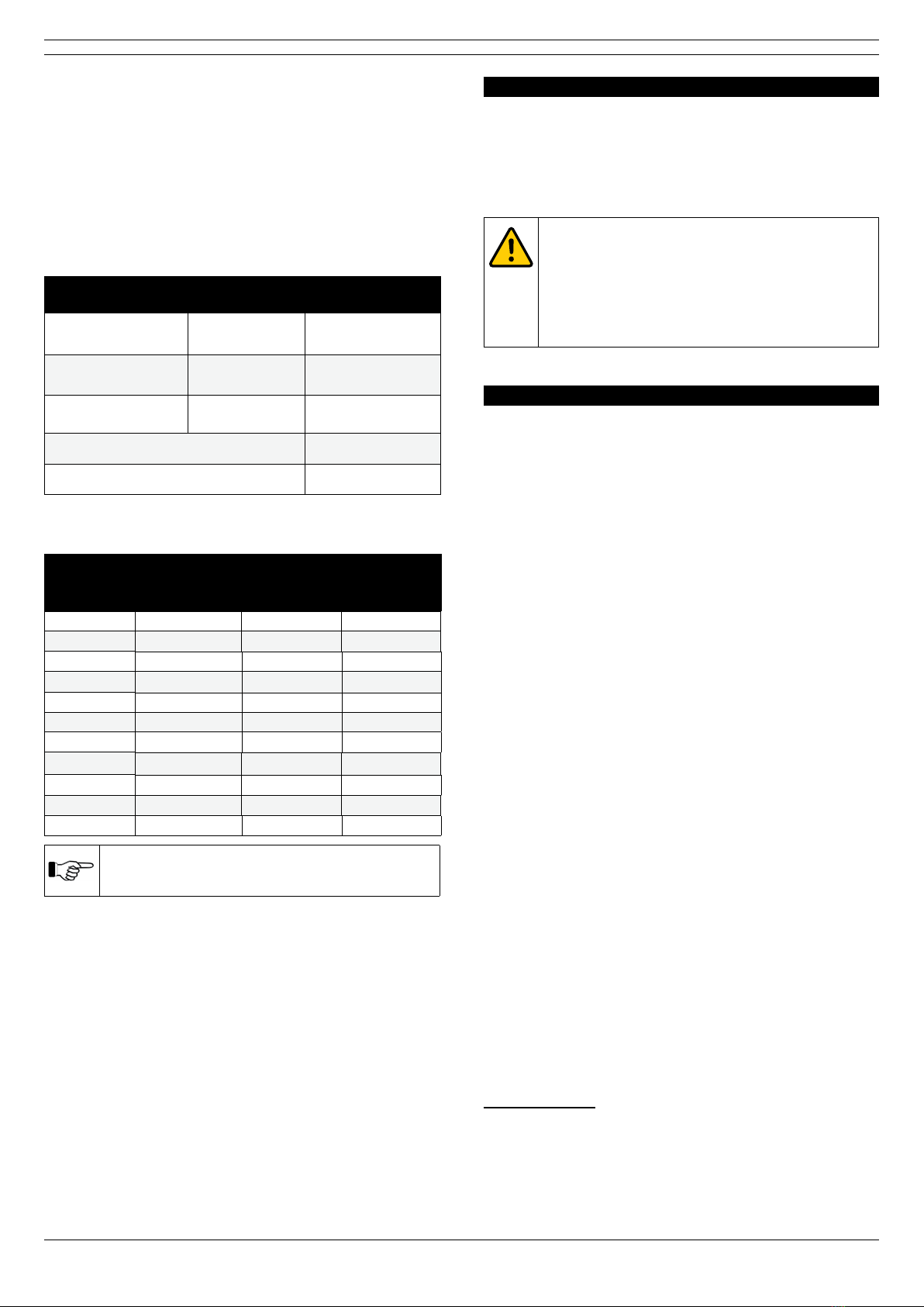
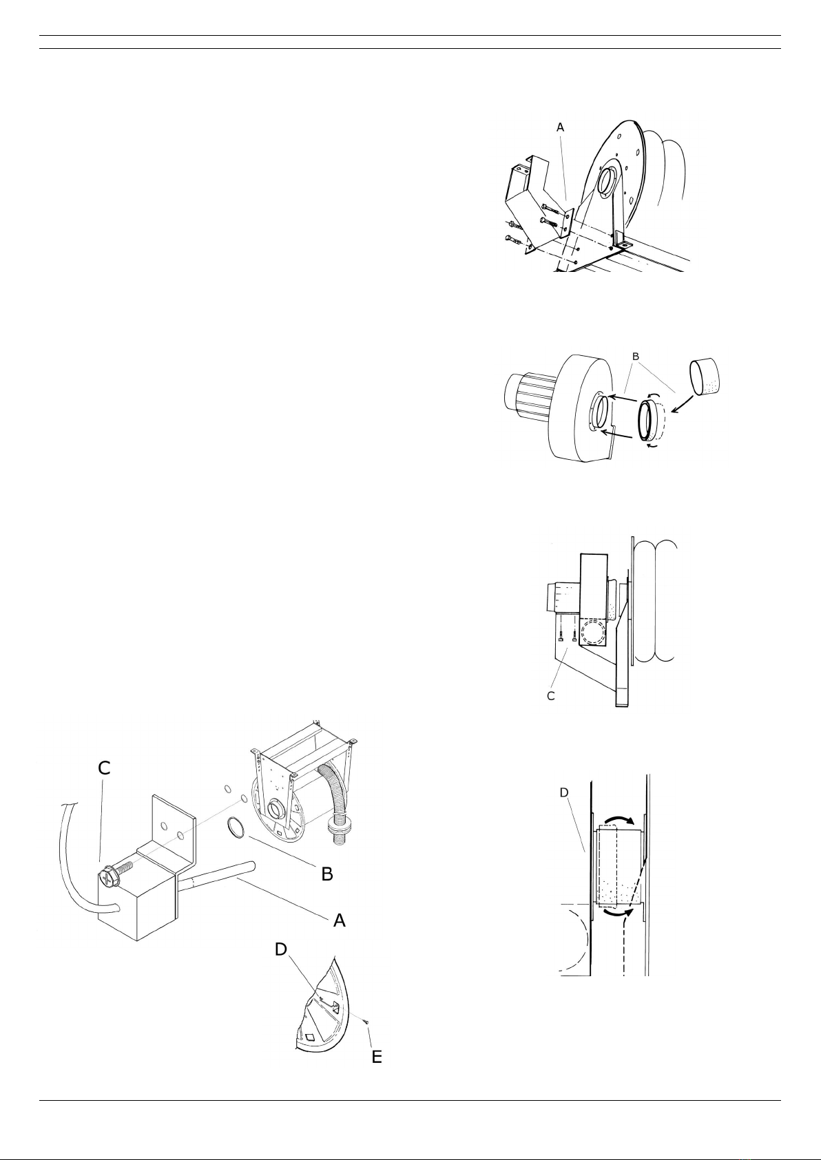
For example, a 125 mm (5 in.) standard hose can be wrapped
around the drum for a maximum of ve rotations, which would
equal 8,2 m (27 ft). The table below demonstrates the total
weight of the Plymovent EF hose, REGD nozzle and rubber
hose stop. Each system’s total weight will vary.
Component Weight
calculation Total weight
125 mm hose 1,09 kg/m
(0.7 lbs/ft) 8,9 kg (19,6 lbs)
Rubber nozzle
REGD-150-160 2 kg (4.4 lbs) 2 kg (4.4 lbs)
Rubber hose stop 2,7 kg (6 lbs) 2,7 kg (6 lbs)
Total weight of hose and components: 13,6 kg (27 lbs)
SER lifting capacity (single cassette): 18,2 kg (40 lbs)
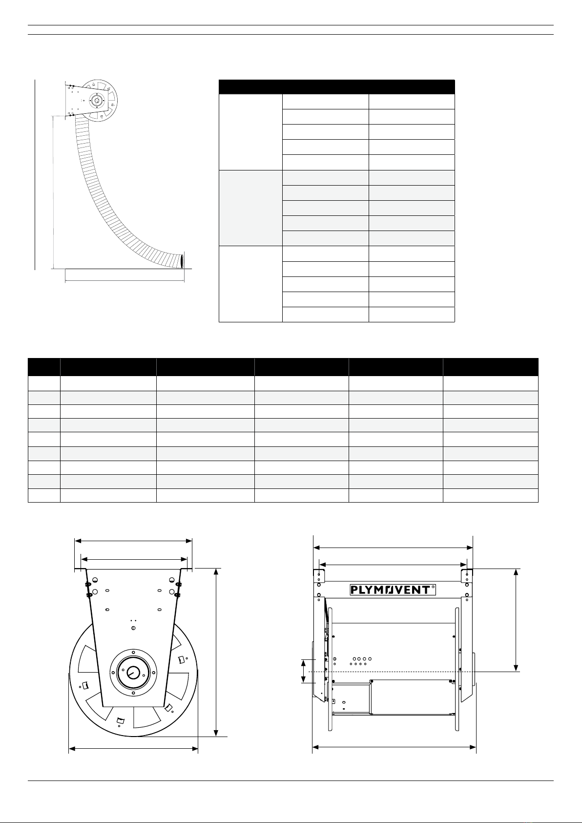
1.4.2 Weight of SER Unit without components
Product Hose
diameter
Maximum
hose length
on reel
Weight
without
components
SER-45 0 -75 Ø 75 mm (3 in.) 7,5 m (24.6 ft) 44 kg (97 lbs)
SE R- 450 -10 0 Ø 100 mm (4 in.) 6 m (19.7 ft) 44 kg (97 lbs)
SER-650-100* Ø 100 mm (4 in.) 10 m (33 ft) 49 kg (108 lbs)
SER-650-125* Ø 125 mm (5 in.) 7,5 m (25 ft) 49 kg (108 lbs)
SER-850-100 Ø 100 mm (4 in.) 10 m (33 ft) 54 kg (119 lbs)
SER-850-125 Ø 125 mm (5 in.) 10 m (33 ft) 54 kg (119 lbs)
SER-850-150 Ø 150 mm (6 in.) 10 m (33 ft) 54 kg (119 lbs)
SER-1050-100 Ø 100 mm (4 in.) 12,5 m (41 ft) 56 kg (123 lbs)
SER-1050-125 Ø 125 mm (5 in.) 12,5 m (41 ft) 56 kg (123 lbs)
SER-1050-150 Ø 150 mm (6 in.) 12,5 m (41 ft) 56 kg (123 lbs)
SER-1050-200 Ø 200 mm (8 in.) 10 m (33 ft) 56 kg (123 lbs)
If a second spring cassette is included, add 7,7 kg
(17 lbs) to the product weight.
1.5 Dimensions
Refer to section 4.2 and 4.3 for dimensions and weights.
1.6 Transport of the unit
The manufacturer cannot be held liable for any transportation
damage after shipment of the unit. Always handle the unit and
the accompanying options and/or accessories, if any, with
care.
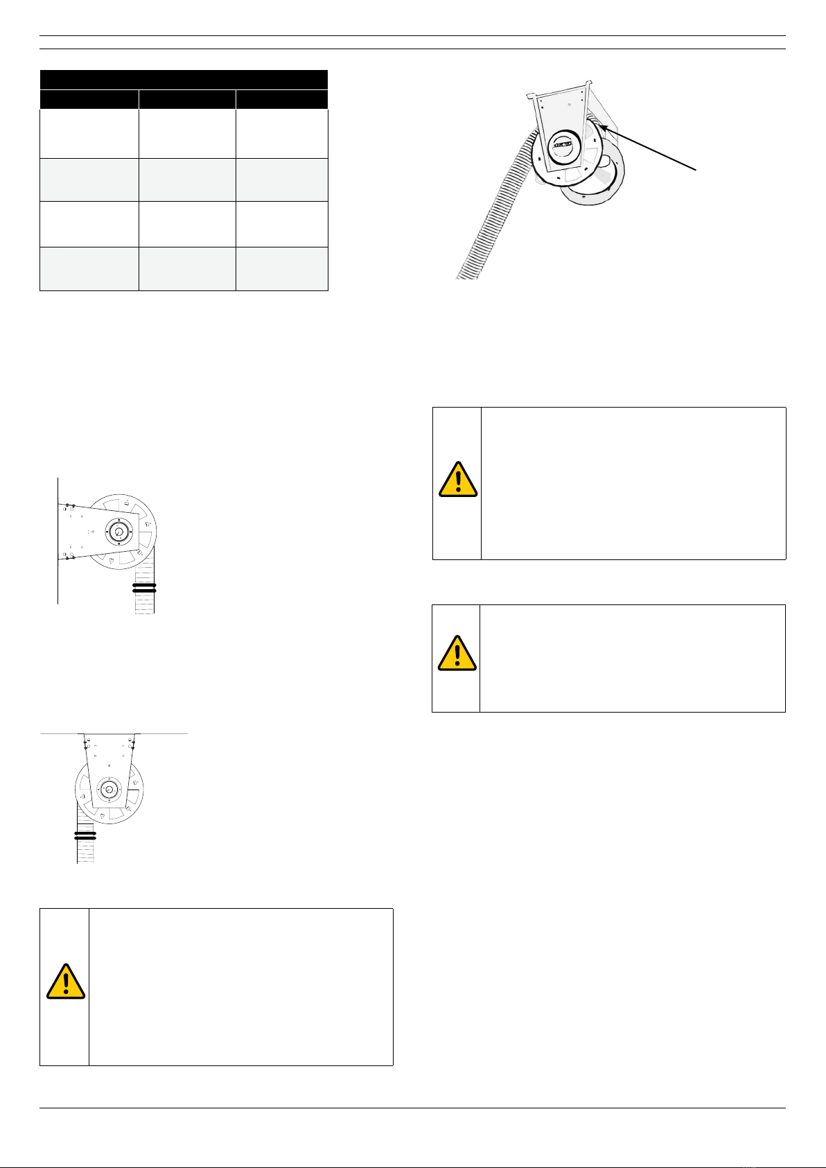
The hose reel is bolted on a skid and delivered with a ceiling or
wall mounting bracket. Based on SER being ordered, the duct
connection includes either a Ø 165 mm (6.5 in.) with reducer
to 160 mm (6 in.) or a Ø 200 mm (8 in.) duct connection
collar.
2 PRODUCT DESCRIPTION
2.1 Operation
SER works according to the “blind” principle. The operator
pulls the hose to lock it into the required position and pulls a
second time to recoil the hose on the reel. The hose stopper is
set to the required height when returning the hose to the reel.
WARNING!
The sealed spring cassette contains a powerful
spring and must not be opened. Be careful when
servicing the SER product. If you have any
questions about the content in this manual, please
contact Plymovent or your Plymovent authorised
distributor. Be careful when operating the hose reel
so as to avoid damage to persons and property.
3 SAFETY INSTRUCTIONS
General
The manufacturer does not accept any liability for damage to
the product or personal injury caused by ignoring the safety
instructions in this manual, or by negligence during
installation, use, maintenance, and repair of the product
mentioned on the cover of this document and any
corresponding accessories. Specic working conditions or used
accessories may require additional safety instructions.
Immediately contact your supplier if you detect a potential
danger when using the product.
The user of the product is always fully responsible for
observing the local safety instructions and regulations.
User manual
- Everyone working on or with the product must be familiar
with the contents of this manual and must strictly observe
the instructions therein. The management should instruct the
personnel in accordance with the manual and observe all
instructions and directions given.
- Never change the order of the steps to perform.
- Always keep the manual with the product.
Pictograms and instructions on the product (if
present)
- The pictograms, warning and instructions attached to the
product are part of the safety features. They must not be
covered or removed and must be present and legible during
the entire life of the product.
- Immediately replace or repair damaged or illegible
pictograms, warnings and instructions.
Users
The use of this product is exclusively reserved to authorised,
trained and qualied users. Temporary personnel and
personnel in training can only use the product under
supervision and responsibility of skilled engineers.
Intended use1
The product has been designed to extract exhaust gases.
Using the product for other purposes is considered contrary to
its intended use. The manufacturer accepts no liability for any
damages or injury resulting from such use. The product has
1 “Intended use” as explained in EN-ISO 12100 is the use for which the technical
product is suited as specied by the manufacturer, inclusive of his directions in
the sales brochure. In case of doubt it is the use which can be deduced from
the construction, the model and the function of the technical product which is
considered normal use. Operating the machine within the limits of its intended
use also involves observing the instructions in the user manual.
*650 models are not available in USA and Canada.

0000110982/231018/A SER EN - 5
been built in accordance with state-of-the-art standards and
recognized safety regulations. Only use this product when in
technical perfect condition in accordance with its intended use
and the instructions explained in the user manual.
Technical specications
The specications given in this manual must not be altered.
Modications
Modication is not allowed.
Installation
- The installation of this product is exclusively reserved to
authorised, well-trained and qualied engineers.
- Inspect the product and check it for damage. Verify the
functioning of the safety features.
- Never install the product in front of entrances and exits
which must be used for emergency services.
- Make sure that the workshop, in the vicinity of the product,
contains sucient approved re extinguishers.
Please note that additional tools and machines may be needed
depending on the installation situation (installation height,
space available etc).
Use
- Check the working environment. Do not allow unauthorised
persons to enter the working environment.
- Protect the product against water and humidity.
- Use common sense. Stay alert and keep your attention to
your work. Do not use the product when you are under the
inuence of drugs, alcohol or medicine.
- Make sure the room is always suciently ventilated;
this applies especially to conned spaces.
Operating the system
- With SER, an operator pulls the hose down, which releases
the ratchet lock; the operator connects the nozzle and when
the hose is no longer needed, the operator pulls down on the
hose to release the ratchet lock and guides the hose back to
its rest position, which is determined by the hose stop-ring.
Service, maintenance and repairs
- This manual contains instructions for replacing the hose,
replacing the cassette and replacing bearings. Refer to the
Maintenance section in this manual for details.
WARNING!
Maintenance should only be performed by
authorised, qualied and trained persons (skilled)
using appropriate work practices.
4 INSTALLATION
4.1 Assembly
Tools:
These tools are needed to install SER:
- Power Drill/Electric Screw gun
- General hand tools/wrenches
- Screw drivers
Complete these steps to install the SER hose reel, as indicated
in g. 4.1a.
• Set the tension on the exhaust reel according to the
Pre-tension table in this section. Turn the drum in the
direction of the arrow; see arrow on the sticker of spring
housing.
• Dismantle drum lid A (not needed for SER-1050-200
version)
• Mount MAS Kit.
• Mount hose to the socket inside the drum using clamp (E).
• Bend hose into a natural soft curve and fasten it using
clamp (B).
• Re-mount the drum lid (A).
• Mount the edge protection (C) at the opening of the drum
where the hose protrudes.
• Mount the hose stop-ring (D) so that the hose stops at a
convenient height when it is reeled in.
• The console holes are pre-set for the correct diameter
hose, as shown in g. 4.1b.
Fig. 4.1a Hose reel assembly
Note: For the SER-1050-200 version, the MAS kit is not
needed, as it uses a dierent hose mounting method for
the 200 mm (8 in.) hoses.
Fig. 4.1b Hose reel console holes
Ø 150 mm (6 in.)
Ø 125 mm (5 in.)
Ø 100 mm (4 in.)
Ø 75 mm (3 in.)

0000110982/231018/A SER EN - 6
SER pre-tension table
Hose Ø Hose length Pre-tension
100 mm 5 m (16 ft)
7,5 m (25 ft)
10 m (33 ft)
5 turns
6 turns
7 turns
125 mm 5 m (16 ft)
7,5 m (25 ft)
10 m (33 ft)
6 turns
7 turns
8 turns
150 mm 5 m (16 ft)
7,5 m (25 ft)
10 m (33 ft)
7 turns
8 turns
10 turns
200 mm 5 m (16 ft)
7,5 m (25 ft)
10 m (33 ft)
4 turns
5 turns
7 turns
Note: The pre-tension turns in this table may vary based on
the type of hose being used. We recommend you set up
one reel and test for performance. Then tension the
other reels as needed.
4.2 Height and dimensions
4.2.1 Wall mounting maximum height
Use the Reach and mounting height chart for specic hose
lengths and maximum hose reach, as shown in g. 4.2.1.
Fig. 4.2.1 Mounting hose reel on wall
4.2.2 Ceiling mounting maximum height
Use the Reach and mounting height chart for specic hose
lengths and maximum hose reach, as shown in g. 4.2.2.
Fig. 4.2.2 Mounting hose reel on ceiling
WARNING!
After installation, operators must be made aware
that a “quarter turn” of the hose should always
remain on the drum, as shown in g. 4.2.2a.
If the hose is pulled down completely, the entire
hose is removed from the drum and the recoil
mechanism is locked. The hose reel will no longer
retract the hose. If this occurs, the drum must be
turned manually by the drum plate for the recoil
mechanism to release.
CAUTION!
When the reel is mounted to a rigid structure like an
iron beam or concrete, then use the dimensions
provided. However, when the reel is being mounted
to porous or otherwise doubtful materials like hollow
brick, threaded rod, lightweight concrete, plaster
etc., please consult a Plymovent expert.
Fig. 4.2.2a Example of SER showing
that at least a quarter turn
of hose must remain on
drum to prevent recoil
mechanism from locking.
ATTENTION
When horizontally mounting a reel that contains
either a 150 mm or 200 mm (6 in. or 8 in.) hose, it
is recommended that you attach the hose so that it
rotates around the “front” of the hose reel drum
(away from the column or wall).
This will prevent the hose from scraping the
horizontal “console” bar, or colliding with any items
attached to the column or wall below the reel.

0000110982/231018/A SER EN - 7
A
B
C
4.2.3 Reach and mounting height
4.2.4 Hose reel dimensions (nominal)
SER-450 SER-650 SER-850 SER-1050 SER-1050-200
A630 mm (24.8 in.) 830 mm (32.7 in.) 1030 mm (40.5 in.) 1230 mm (48.4 in.) 1255 mm (49.4 in.)
B500 mm (19.7 in.) 500 mm (19.7 in.) 500 mm (19.7 in.) 500 mm (19.7 in.) 527 mm (20.7 in.)
C574 mm (22.6 in.) 774 mm (30.5 in.) 974 mm (38.3 in.) 1174 mm (46.2 in.) 1374 mm (54 in.)
DØ 160 mm (6.30 in.) Ø 160 mm (6.3 in.) Ø 160 mm (6.3 in.) Ø 160 mm (6.3 in.) Ø 200 mm (8 in.)
E790 mm (31 in.) 790 mm (31.1 in.) 790 mm (31.1 in.) 790 mm (31.1 in.) 965 mm (38 in.)
F* 650 mm (25.6 in.) 870 mm (34.3 in.) 1070 mm (42.1 in.) 1270 mm (50 in.) 1295 mm (51 in.)
G600 mm (23.6 in.) 600 mm (23.6 in.) 600 mm (23.6 in.) 600 mm (23.6 in.) 737 mm (29 in.)
H552mm (21.7 in.) 552 mm (21.7 in.) 552 mm (21.7 in.) 552 mm (21.7 in.) 578 mm (22.7 in.)
I489 mm (19.2 in.) 489 mm (19.2 in.) 489 mm (19.2 in.) 489 mm (19.2 in.) 590 mm (23.2 in.)
Hose length Mounting height Maximum reach
7,5 m (25 ft)
3 m (9.8 ft) 6,2 m (20.4 ft)
3,5 m (11.5 ft) 5,9 m (19.4 ft)
4 m (13.1 ft) 5,5 m (18 ft)
4,5 m (15 ft) 5,2 m (17.1 ft)
5 m (16.4 ft) 4,7 m (15.5 ft)
10 m (33 ft)
3,5 m (11.5 ft) 8,5 m (28 ft)
4 m (13.1 ft) 8,3 m (27.3 ft)
4,5 m (15 ft) 8 m (26.3 ft)
5 m (16.4 ft) 7,7 m (25.3 ft)
5,5 m (18 ft) 7,4 m (24.3 ft)
12,5 m (41 ft)
5 m (16.4 ft) 10,6 m (35 ft)
5,5 m (18 ft) 10,3 m (34 ft)
6 m (19.7 ft) 10 m (33 ft)
6,5 m (21.4 ft) 9,7 m (32 ft)
7 m (23 ft) 9,4 m (31 ft)
A = Mounting height
B = Hose length
C = Max. reach
*If a second spring cassette is added to the SER 850 or 1050 reel, add 65 mm (2.6 in.).
Note: Remember to
consider the hose
reel’s lifting
capacity when
mounting at
higher elevations,
factoring in the
total weight of the
hose, nozzle and
rubber hose stop.
F
A
C
B
G
E
H
D
I
Fig. 4.2.3 Hose reel reach and mounting
Fig. 4.2.4a Hose reel side view Fig. 4.2.4b Hose reel front view

0000110982/231018/A SER EN - 8
Fig. 4.3.1a Inserting the DMF bracket into the hose reel
Fig. 4.3.1b Inserting the DMF bracket into the hose reel
Fig. 4.3.1c Tightening the bolts on the DMF bracket
Fig. 4.3.1d Mounting the operating springs on the hose reel drum
4.3 Mounting options
4.3.1 Direct mount fan
The SER includes ceiling or wall mounting attachment foot. All
SER versions except for 1050-200 can be connected to a
central exhaust system or tted with a fan.
First, mount the fan with the reel upside down on the oor and
then mount the complete reel to its intended position, as
shown in g. 4.3.1a through g. 4.3.1d.
• With hose reel securely installed in position or placed on a
level working surface, insert the DMF Bracket with the bolts
and hand tighten the nuts into position (A).
• Place rubber collar on the inlet spigot of fan (B).
• Align fan bolt holes with the holes in the fan bracket. Insert
bolts and tighten slightly. Slide the bracket up and down
parallel to the A-frame center to align with the hose reel
outlet. Tighten bolts to ensure the unit is properly secured
(C).
• Unfold the rubber collar over the reel’s spigot (For North
America customers, a synthetic rubber-coated sleeve is
applied with two hose clamps) (D).
Note: Direct mount fans are PV Model FUA-1800, 2100 or
2700. Refer to FUA fan product data sheet for additional
data.
4.3.2 Micro Switch MSR-24/2
To insert the micro switch, follow these steps, as shown in g.
4.3.2.
• Insert the circuit-breaker’s feeler (A) into the hole (B).
• Secure circuit-breaker using enclosed screws (C).
• Check that the circuit-breaker can move freely in both
directions.
• Pull out the hose and obtain 4 notches on one of the lock
segments.
• Mount the operating springs (D) on the drum by loosening
two of the screws (E) that hold the drum.
• Refasten screws.
• For electrical installation, refer to the electrical connection
schematic in the manual for the specic controller that is
being used in the installation.
Fig. 4.3.2 Inserting the micro switch

0000110982/231018/A SER EN - 9
4.3.3 SER on a boom
Note: The boom (articulated arm) cannot be used with the
SER-1050-200 hose reel.
Product Reach
mm (in.)
Max stretching/
bolt
kp (ft. lbs)
Torque
demands/bolt
kp (ft. lbs)
EB-3.5 3500 (11.5) 650 (1430) 1950 (4299)
EB-4.5 4500 (14.7) 900 (1984) 2700 (5952)
Follow these steps to install the articulated arm, as shown in
g. 4.3.3a through 4.3.3d:
• Bolt mounting bracket (A) to wall or steel column; to
ensure a level mounting, level to the pivot pin on the wall
bracket, and not the edge of the steel plate.
• If included, mount the fan (B) with a MB-FUA-C1/C2
bracket (also referred to as the FUK bracket).
• Mount the extractor arm (C). Tighten to torque values
noted in the table above.
• Set friction by tightening the bolt at swivel joint, until the
arm remains in one position; this is done while attaching
the reel and duct (D).
• Mount hose reel to boom arm.
• Mount spiro-tubing and hose on the boom arm (E).
• Mount ducting bend to hose reel, then mount the hose to
the ducting bend (F).
• Readjust friction as needed (G).
Fig. 4.3.3a Mounting bracket for EB-3.5, EB-4.5
4.3.4 Factory-installed mechanical damper
Based on the facility design requirements, a sealed closing
damper, as shown in g. 4.3.4, may have been factory
installed on the duct portion of the hose reel. In a facility that
includes multiple hose reels, this
built-in mechanical damper allows
airow only through hose reels
currently in use, reducing energy
costs. The damper opens
automatically when the hose is
lowered (2 rotations), and closes
when the hose is raised by the
operator.
This damper is typically used when
there are no other dampers
installed in the duct work, and no
electronic control units are being
installed.
Fig. 4.3.4 Mechanical damper
Fig. 4.3.3b Mounting the fan to the bracket
Fig. 4.3.3c Mounting the reel to the boom arm
Fig. 4.3.3d Mounting duct to the boom arm
F
G
E
B
C
D
Ø 15 mm
(19/32 in.)
200 mm (7.9 in.)
420 mm (16.5 in.)
A
150 mm (5.9 in.)

0000110982/231018/A SER EN - 10
5 MAINTENANCE
5.1 Replacing the exhaust hose
• Uncoil hose completely and lock reel in its most extended
position. See Fig. 5.1 and follow the steps below.
• Dismantle edge list (C), drum lid (A), and clamp (B).
• Loosen hose clip (E) on the connecting socket and remove
the old hose.
• Attach new hose, bend it into a natural soft curve and
fasten it using clamp (B).
• Re-mount the drum lid (A).
• Re-mount the edge protection (C) at the opening of the
drum where the hose protrudes. The reel is ready for use.
B
D
C
E
A
Fig. 5.1 Replacing the exhaust hose
5.2 Replacing the spring cassette
• As shown in g. 5.2, take o the hose stopper and tailpipe
adapter (A) and allow the hose to completely coil onto the
reel (B).
• Turn the reel four revolutions ”backwards” in order to
equalise the spring-tension (if the spring still functions).
• Unscrew all socket head cap screws at the spring casing
(C). Mark the position of the spring casing.
• Put the new spring casing in position. Tighten the bolts
evenly.
• ”Pre-tension” the reel about seven revolutions. Put the
hose stopper in position.
5.3 Exchanging the plastic bearings
To safely perform this operation, it is recommended that you
dismantle the reel and stand it on the oor. See Fig. 5.3 and
follow the steps below.
• Make sure hose is completely rewound on the reel. Turn
the reel approximately seven revolutions ”backwards” in
order to cancel the spring-tension (A).
• Loosen the leg on the side of the spring by loosening the
bolts on the beam (B).
• Remove the drum from the reel.
• Change the plastic bearing (C).
• Unscrew the drum lid (D). Dismantle the connecting socket
(E) and change the plastic bearing (F).
• Reassemble in reverse order.
Fig. 5.3 Replacing the plastic bearings
Fig. 5.2 Replacing the spring cassette
A
B
C

0000110982/231018/A SER EN - 11
6 DISPOSAL
After life of the product, dispose it of in accordance with state
or local regulations.
7 PRESSURE LOSS CALCULATION
The fall of pressure in a air duct system or in a hose is mainly
determined by the air velocity in that system.
The higher the velocity is, the higher the pressure loss will be.
And the higher the pressure loss is, the less air the fan will
extract. See g. 7.1 for a Pressure Loss Chart to identify a
suitable fan regarding the relationship between airow and
pressure loss.
In a ventilation system with many extraction devices and long
suction ducts, you can minimise pressure loss by increasing
the size of the ducting. This will also ensure even velocity
throughout the system.
Hose diameter Length
A Ø 100 mm (4 in.) 7,5 m (24.7 ft)
B Ø 100 mm (4 in.) 10 m (33 ft)
C Ø 100 mm (4 in.) 12,5 m (41 ft)
D Ø 125 mm (5 in.) 7,5 m (24.7 ft)
E Ø 125 mm (5 in.) 10 m (33 ft)
F Ø 125 mm (5 in.) 12,5 m (41 ft)
G Ø 150 mm (6 in.) 7,5 m (24.7 ft)
H Ø 150 mm (6 in.) 10 m (33 ft)
I Ø 150 mm (6 in.) 12,5 m (41 ft)
J Ø 200 mm (8 in.) 10 m (33 ft)
Note: 75 mm (3 in.) hoses are not available in North America.
A
B
C
D
E
F
G
H
I
J
Airflow Volume: General Guidelines
Vehicles serviced m3/h
(cfm)
Hose
diameter
Automobile / Motorcycles 460-510
(270-300) Ø 100 mm (4 in.)
Trucks (Public Works,
Rental Fleets, etc.)
850-935
(500-550) Ø 125 mm (5 in.)
Heavy Duty Trucks 1100-1360
(650-800) Ø 150 mm (6 in.)
Off-Road (Constr.,
Compressor Tests, etc.)
1700-2400
(1000-1400) Ø 200 mm (8 in.)
When 1200 to 1350 m3/h is needed, Plymovent recommends a
150 mm (6 in.) hose. A 200 mm (8 in.) hose can be used for
larger applications, as it supports larger engines operating
under load. For those cases, the exhaust ow and temperature
increase dramatically.
Air velocity in ducting: 17,8 - 22,9 m/s (3500 to 4500 fpm).
The chart below shows the pressure loss in the hose reels a
dierent airows. Refer to the Airow Volume: General
Guidelines table below for the vehicle, airow and hose
diameter guidelines. The curves show these combinations of
hose reel/hose diameter/hose length (uncoiled position).
We recommend that you conrm existing exhaust
temperatures to ensure proper hose, fan and
airow selection.
Fig.7.1 Pressure loss chart

0000110982/231018/A SER EN - 12
8 SER SPARE PARTS
How to order spare parts:
At this time, Plymovent is reviewing spare parts for this hose reel. Please contact your authorized distributor to discuss the spare
part that you need. You can identify your authorized distributor at https://www.plymovent.com - click the “Contact Plymovent”
link and then click “Sales Oces.”
CE DECLARATION
CE declaration of conformity for machinery
We, Plymovent, Koraalstraat 9, 1812 RK Alkmaar, the Netherlands,
herewith declare, on our own responsibility, that the product(s):
- Spring Operated Exhaust Hose Reel (SER)
is in conformity with the following harmonized standard(s)
and/or other such normative documents + amendments, if any:
EN ISO 12100:2010
Alkmaar, the Netherlands, October 23th, 2018
Kees Janssen
Product Manager EE

www.plymovent.com
0000110982/231018/A SER
This manual suits for next models
12
Table of contents
Other Plymovent Tools manuals