0000302684/02NOV22/A SER EN - 4
2 PRODUCT DESCRIPTION
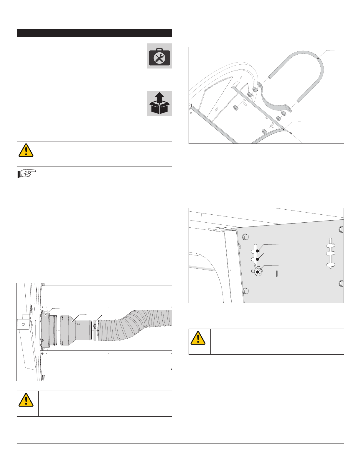
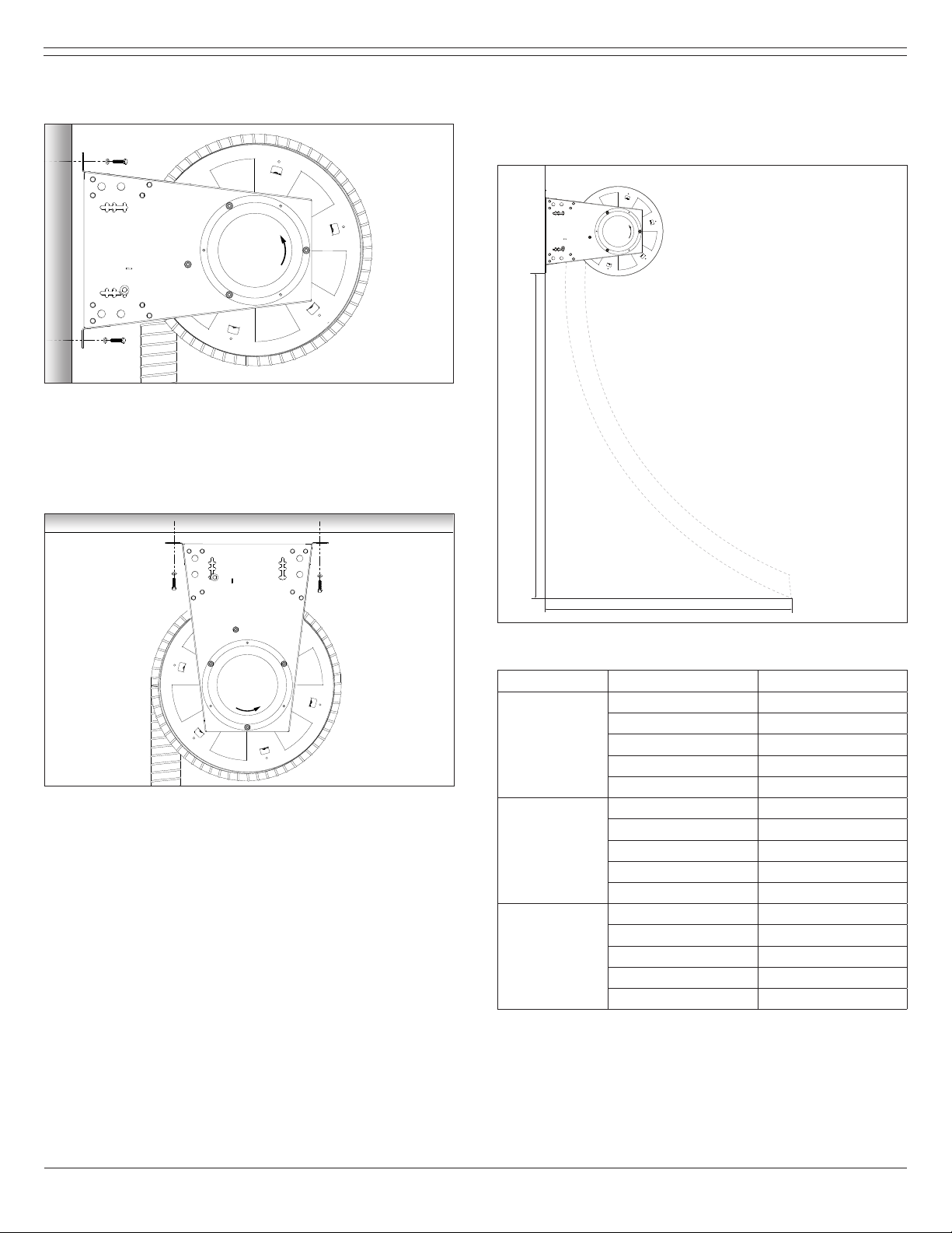
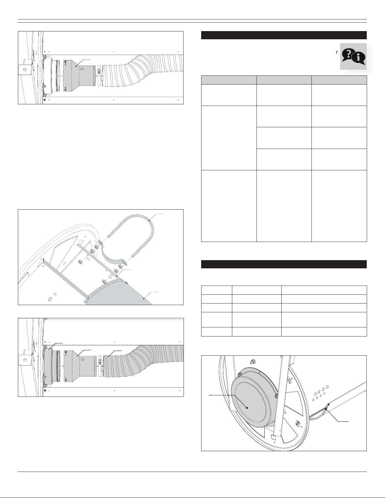
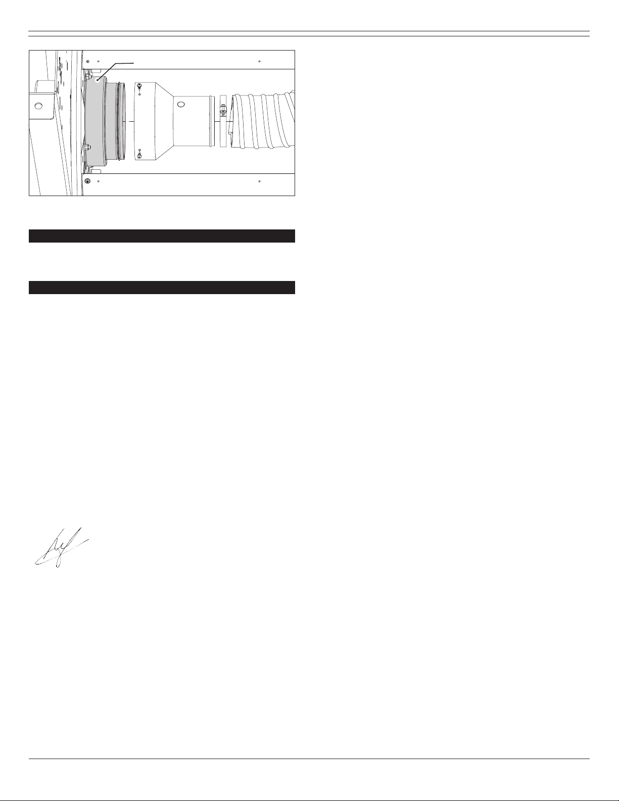
2.1 Product components
The product consists of the following main components and
elements (g. 2.1):
A Mounting beams
B A-frame spring side
C A-frame air side
D Drum
Fig. 2.1 Product components
3 SAFETY INSTRUCTIONS
General
The manufacturer does not accept any liability for damage to
the product or personal injury caused by ignoring of the safety
instructions in this manual, or by negligence during installation,
use, maintenance, and repair of the product mentioned on the
cover of this document and any corresponding accessories.
Specic working conditions or used accessories may require
additional safety instructions. Immediately contact your supplier
if you detect a potential danger when using the product.
The user of the product is always fully responsible for
observing the local safety instructions and regulations.
Observe all applicable safety instructions and regulations.
User manual
- Everyone working on or with the product, must be familiar
with the contents of this manual and must strictly observe
the instructions therein. The management should instruct the
personnel in accordance with the manual and observe all
instructions and directions given.
- Do not change the order of the steps to perform.
- Keep the manual with the product.
Users
- The use of this product is exclusively reserved to authorised,
trained and qualied users. Temporary personnel and
personnel in training can only use the product under
supervision and responsibility of skilled engineers.
- Stay alert and keep your attention to your work. Do not use
the product when you are under the inuence of drugs,
alcohol or medicine.
- The product is not to be used by children or persons with
reduced physical, sensory or mental capabilities, or lack of
experience and knowledge, unless they have been given
supervision or instruction.
- Children must be supervised not to play with the product.
Technical specications
Do not change the specications given in this manual.
Modications
Modication of (parts of) the product is not allowed.
Installation
- The installation of this product is exclusively reserved to
authorised, trained and qualied engineers.
- The electric connection must be executed in accordance with
the local codes and requirements. Ensure compliance with
the EMC regulatory arrangements.
- During installation, always use Personal Protective
Equipment (PPE) to avoid injury. This also applies to persons
who enter the work area during installation.
- Use sucient climbing gear and safety guards when working
on a higher level than 2 metres (local restrictions may
apply).
- Do not install the product in front of entrances and exits
which must be used for emergency services.
- Mind any gas and water pipes and electric cables.
- Make sure that the workspace is well illuminated.
- Stay alert and keep your attention to your work. Do not
install the product when you are under the inuence of
drugs, alcohol or medicine.
- Air containing particles such as chromium, nickel, beryllium,
cadmium, lead etc., should never be recycled. This air must
always be brought outside the working area.
Use
- Inspect the product and check it for damage. Verify the
functioning of the safety features.
- Check the working environment. Do not allow unauthorised
persons to enter the working environment.
- Protect the product against water and humidity.
- Make sure the room is always suciently ventilated; this
applies especially to conned spaces.
- Make sure that the workshop, in the vicinity of the product,
contains sucient approved re extinguishers (suitable for re
classes ABC).
Service, maintenance and repairs
- Obey the maintenance intervals given in this manual. Overdue
maintenance can lead to high costs for repair and revisions and
can render the guarantee null and void.
- Always use Personal Protective Equipment (PPE) to avoid
injury. This also applies for persons who enter the work area.
- Make sure the room is suciently ventilated.
- Use tools, materials, lubricants and service techniques which
have been approved by the manufacturer. Never use worn
tools and do not leave any tools in or on the product.
- Use sucient climbing gear and safety guards when working
on a higher level than 2 metres (local restrictions may apply).
- Clean the area afterwards.
B
C
D