manuals.online logo
Brands
  1. Home
  2. •
  3. Brands
  4. •
  5. PMV Mounts
  6. •
  7. TV Mount
  8. •
  9. PMV Mounts PMVTROLLEY2 User manual

PMV Mounts PMVTROLLEY2 User manual

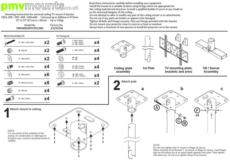
Read these instructions carefully before assembling this equipment.
Only use fixings provided with this bracket.
Do not use if any parts are broken or appear to be damaged.
Check the equipment has been supplied with all parts and fixtures prior to assembly.
Do not attempt to alter or modify any part of the equipment or its attachments.
Assemble in a suitable location.
Two people will be required for assembly and for installation of the screen on to the equipment.
Tighten all bolts and fixings securely with appropriately sized tools.
Do not position the equipment close to sources of heat or moisture.
Component checklist
600mm aluminium extrusion assembled with joining plate x1
TV mounting plate x1
Tilting VESA plate x1
Upright trim x1
Glide feet x4
50mm castors x2 50mm braked castors x2
TV mounting plate
sliders x2
600mm trim inserts x3
Vertical TV mounting arms x2
Horizontal TV mounting arms x2
Welded base unit assembled with colour coded trims x1
900mm aluminium extrusion assembled with joining plate x1
Assembly kit checklist
F - M8 nut
A - M6 x 12mm
D - M8 x12mm
C - M8 washer
B - M8 x 65mm
X16
X3
X17
X3
X4
TV Fixing Kit
G - M4 x 20mm
J - M8 x 20mm
I - M6 x 20mm
H - M5 x 20mm
M - M8 washer
L - M6 washer
K - M5 washer
N - M4 x 5mm
Q - M6 x 6mm
P - M6 x 6mm
O - M5 x 5mm
X4
X4
X4
Cable
management
gully
Rear face of extrusion
Trim insert
Trim insert
Front face of extrusion
Slider gully
Top down view
Isometric view
Cable Management: Some forward planing may be required regarding the cable routing of your
trolley and installation. All plug or socket types may not pass through the gully post assembly and
may need to be tucked in to position during the assembly of the base and uprights.
Trim inserts: Trim inserts will need to be cut to size with sharp scissors. Trim inserts can be inserted
via an open end of the extrusion, this will need to be carried out during assembly of the stand. Or the
trim inserts can be ‘popped’ in to place post assembly by inserting one side of the trim in to the
corresponding groove and pushing the opposing side with your thumbs in to the opposing groove of
the extrusion.
Note: The trim pieces can be cut with a safety knife to make small entry and exit points for cables.
E - M8 x 12mm X10
Also requiredAllen keys included
X3
Designed & Manufactured
in the United Kingdom
pmvmounts.co.uk
Assembly instructions for TV trolley
Maximum TV fixing points up to 800mm X 400mm - Up to 40Kgs
Model No.
PMVTROLLEY2
Factory No.
Z3255TRV2
Attach castors or feet to base unit. The base comes preassembled with welded mounting plates, welded bracing and bonded aesthetic trim pieces.
1. Carefully turn the base upside down and attach x4 castor or x4 feet to all x4 corners as pictured Fig 1A.
2. Castors install using x4 fixings to each of the x4 welded fixing plates on the underside of the base, position x2 braked castors at the rear of the base Fig 1B.
3. Glide feet install directly into the welded fixing plates in the centre hole, adjust the feet to until the base is level and tighten with the half nut Fig 1C.
1
Position and fasten extrusions to base unit.
Both extrusions are preassembled with black joining plates on one end, the extrusions are not handed but need to be assembled with the cable gully facing the rear of the stand.
1. Turn the base over so it is the correct way up. Apply brakes to rear castors, do not stand on the base unit at any time.
2. Insert the open end of the 900mm extrusion into the base and use x3 fittings to fasten to the base unit Fig 2A & Fig 2B
3. Once the 900mm extrusion is secure in the base add the 600mm extrusion to it in via the black joining plates Fig 2C.
4. Insert x2 bolts inside the cable gully to fasten the 600mm extrusion joining plate to the joining plate at the top of the 900mm extrusion and one, a third bolt is required
through the centre hole in the joining plates outside of the extrusions Fig 2D.
2
1A
2C
2D
1B
1C
900mm extrusion
Black joining plates
600mm extrusion
Dx3
Ax16
2B Underside of base unit showing bolt positions.
DO NOT
OVER
TIGHTEN!
2A
Bx4
DO NOT
OVER
TIGHTEN!
Cx4
N-Qx4
Assemble TV mounting plate.
The sliders come with a soft pad on the back edge which help to hold the slider in position within the slider gully, however it must be held at all times until fully tightened.
3A Install the mounting plate sliders inside the TV mounting plate using x4 bolts with washers Fig 3A
3B Leave a gap of 5mm between each slider and the TV mounting plate Fig 3B.
3C Position the TV mounting plate over the extrusion, guide the slider plates into the slider gullies as you lower the TV mounting plate Fig 3C.
3D Lower the TV mounting plate to the desired position and fully tighten all x4 fixing bolts in a diagonal pattern. The height of the screen can be adjusted later if desired Fig 3D.
4A For screens with a VESA pattern of 200 x 200 or less only attach the TV tilt plate flat to the screen using the fixings in your TV Fixing Kit. Use spacers if required Fig 4A.
4B For screens with a VESA pattern larger than 200 x 200 use the 4-piece universal interface placing it flat to the screen using the fixings in your TV Fixing Kit. Use spacers if
required (Fig 4B).
3
4
N-Qx4
N-Q x4
G-Jx4
G-Jx4
Ex4
Cx4
K-Mx4
K-Mx4
5mm
5mm
3A
4A
4B
3C
3B 3D
Note: Use spacers if the screen is uneven in or
around the mounting pattern.
Spacers can be used under the bolt head to reduce
the effect length of the bolt.
Note: Use spacers if the screen is uneven in or
around the mounting pattern.
Note: Spacers can be used
under the bolt head to reduce
the effect length of the bolt.
Up to VESA
75, 100, 200
Over VESA 200
Up to 800 x 600mm
5mm
5mm
Continued:
4C Position horizontal TV arms into the corresponding grooves on the
vertical TV arms, fix in place using x4 bolts with washers - Fig 4C
4D Position TV VESA plate over the studs on the horizontal arms
and fix in position using x4 nuts with washers - Fig 4D
Mount screen to upright assembly.
5A Insure the TV mounting plate is tightened fully and secured at the desired height as per Article 3 on this instruction sheet.
5B Two persons should lift the screen and TV mount to an adequate height and hook it over the corresponding lugs on the TV mounting plate Fig 5B.1 + Fig 5B.2
5C Fit 2x safety bolts through the VESA plate in to the TV mounting plate on each side and tighten once the screen is at the desired angle Fig 5C.
Covers and trims
Install cable management trim inserts as per notes on front page.
Attach top trim by hand.
4
5
6
Tilting VESA plate Horizontal VESA arms
5B.1
Ex4
Cx4
Fx4
Cx4
4C
4D
5C
5B.2
Ex2
Cx2

This manual suits for next models

1

Other PMV Mounts TV Mount manuals

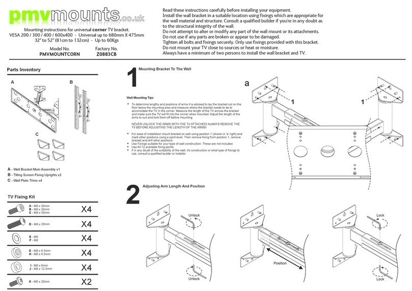
PMV Mounts PMVMOUNTCORN User manual

PMV Mounts

PMV Mounts PMVMOUNTCORN User manual

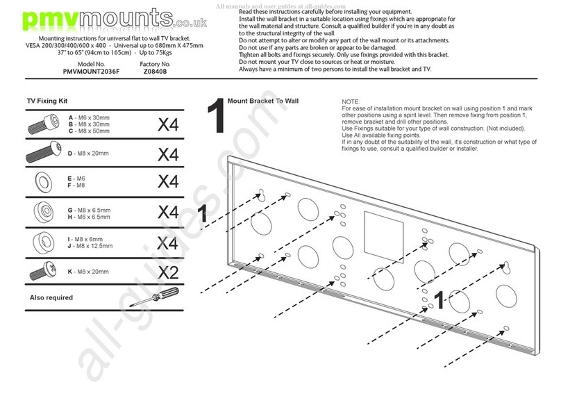
PMV Mounts PMVMOUNT2036F User manual

PMV Mounts

PMV Mounts PMVMOUNT2036F User manual

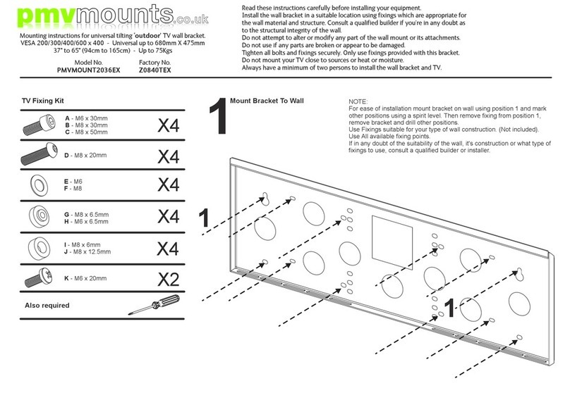
PMV Mounts PMVMOUNT2036EX User manual

PMV Mounts

PMV Mounts PMVMOUNT2036EX User manual

PMV Mounts PMVMOUNTCORNSH User manual

PMV Mounts

PMV Mounts PMVMOUNTCORNSH User manual

PMV Mounts PMVMOUNTMTDX User manual

PMV Mounts

PMV Mounts PMVMOUNTMTDX User manual

PMV Mounts PMVMOUNTECHXFB User manual

PMV Mounts

PMV Mounts PMVMOUNTECHXFB User manual

PMV Mounts PMVMOUNT3246SA User manual

PMV Mounts

PMV Mounts PMVMOUNT3246SA User manual

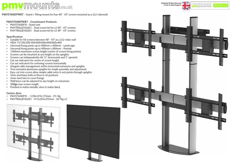
PMV Mounts PMVSTANDFWB7 User manual

PMV Mounts

PMV Mounts PMVSTANDFWB7 User manual

PMV Mounts PMVCEILINGSMALL User manual

PMV Mounts

PMV Mounts PMVCEILINGSMALL User manual

PMV Mounts PMVMOUNTXFBP User manual

PMV Mounts

PMV Mounts PMVMOUNTXFBP User manual

PMV Mounts PMVMOUNTCEILING User guide

PMV Mounts

PMV Mounts PMVMOUNTCEILING User guide

PMV Mounts PMVMOUNTXFBPT User manual

PMV Mounts

PMV Mounts PMVMOUNTXFBPT User manual

PMV Mounts PMVMOUNT2036F User manual

PMV Mounts

PMV Mounts PMVMOUNT2036F User manual

Popular TV Mount manuals by other brands

EDM Product 50133 instruction manual

EDM Product

EDM Product 50133 instruction manual

Velleman WB032 user manual

Velleman

Velleman WB032 user manual

Sanus VLF525 instruction manual

Sanus

Sanus VLF525 instruction manual

CHIEF iC Series installation instructions

CHIEF

CHIEF iC Series installation instructions

Exibel 38-5324 Assembly instructions

Exibel

Exibel 38-5324 Assembly instructions

Pipishell PIMFK1 manual

Pipishell

Pipishell PIMFK1 manual

Grundig GBR-WA04 owner's manual

Grundig

Grundig GBR-WA04 owner's manual

Hama 00118072 operating instructions

Hama

Hama 00118072 operating instructions

Sanus Vuepoint F35c instruction manual

Sanus

Sanus Vuepoint F35c instruction manual

Perlesmith PSTVS03 instruction manual

Perlesmith

Perlesmith PSTVS03 instruction manual

CHIEF PSM-2534 installation instructions

CHIEF

CHIEF PSM-2534 installation instructions

ErgoAV ERMTM2-01B instruction manual

ErgoAV

ErgoAV ERMTM2-01B instruction manual

SIIG Universal Tilting TV Mount - 32" to 60 installation instructions

SIIG

SIIG Universal Tilting TV Mount - 32" to 60 installation instructions

Viega PureFlow 2872.8ZL Product instructions

Viega

Viega PureFlow 2872.8ZL Product instructions

Sonorous PR 2000-N Assembly instructions

Sonorous

Sonorous PR 2000-N Assembly instructions

Desalto Sail 301 Assembly instruction

Desalto

Desalto Sail 301 Assembly instruction

Premier Mounts 7170-0978 Series installation guide

Premier Mounts

Premier Mounts 7170-0978 Series installation guide

Vizio XMA1200 Quick install guide

Vizio

Vizio XMA1200 Quick install guide

manuals.online logo
manuals.online logoBrands
  • About & Mission
  • Contact us
  • Privacy Policy
  • Terms and Conditions

Copyright 2025 Manuals.Online. All Rights Reserved.