Pneumatic Division IS-L35 Installation and maintenance instructions

Introduction
Follow these instructions when installing, operating, or servicing
the product.
Application Limits
These products are intended for use in general purpose
compressed air systems only.
CAUTION
Polyurethane bowls, sight glass and sight domes on these
units may be attacked by certain chemicals. Never use
solvents like carbon tetrachloride, trichlorethylene, acetone,
or paint thinner to clean any parts. These elements can
cause crazing or failure of the plastic parts. The
polyurethane resin parts are compatible with most
hydrocarbon based synthetic lubricants but, before using,
check with the manufacturer of the lubricant or oil for
compatibility with polyurethane resin.
TO CLEAN POLYURETHANE BOWLS USE MILD SOAP
AND WATER ONLY!
WARNING
To avoid unpredictable system behavior that can cause personal injury
and property damage:
• Disconnect electrical supply (when necessary) before installation,
servicing, or conversion.
• Disconnect air supply and depressurize all air lines connected to
this product before installation, servicing, or conversion.
• Operate within the manufacturer’s specified pressure, temperature,
and other conditions listed in these instructions.
• Medium must be moisture-free if ambient temperature is below
freezing.
• Service according to procedures listed in these instructions.
• Installation, service, and conversion of these products must be
performed by knowledgeable personnel who understand how
pneumatic products are to be applied.
• After installation, servicing, or conversion, air and electrical
supplies (when necessary) should be connected and the product
tested for proper function and leakage. If audible leakage is present,
or the product does not operate properly, do not put into use.
• Warnings and specifications on the product should not be covered
by paint, etc. If masking is not possible, contact your local
representative for replacement labels.
WARNING
FAILURE OR IMPROPER SELECTION OR IMPROPER USE OF
THE PRODUCTS AND/OR SYSTEMS DESCRIBED HEREIN OR
RELATED ITEMS CAN CAUSE DEATH, PERSONAL INJURY AND
PROPERTY DAMAGE.
This document and other information from The Company, its
subsidiaries and authorized distributors provide product and/or system
options for further investigation by users having technical expertise. It
is important that you analyze all aspects of your application, including
consequences of any failure and review the information concerning
the product or systems in the current product catalog. Due to the
variety of operating conditions and applications for these products or
systems, the user, through its own analysis and testing, is solely
responsible for making the final selection of the products and systems
and assuring that all performance, safety and warning requirements
of the application are met.
The products described herein, including without limitation, product
features, specifications, designs, availability and pricing, are subject
to change by The Company and its subsidiaries at any time without
notice.
EXTRA COPIES OF THESE INSTRUCTIONS ARE AVAILABLE FOR
INCLUSION IN EQUIPMENT / MAINTENANCE MANUALS THAT UTILIZE
THESE PRODUCTS. CONTACT YOUR LOCAL REPRESENTATIVE.
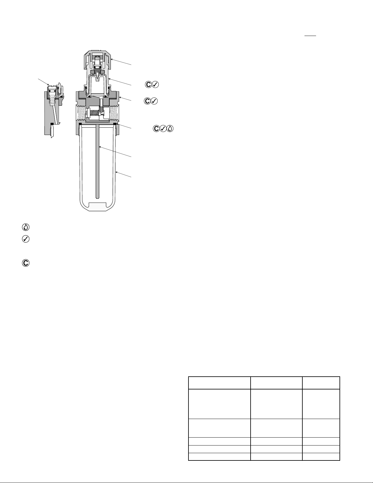
With Polyurethane Bowl
kPa PSIG bar
Operating Pressure Maximum 1034 150 10
Operating Temperature Range 4.4°C to 48.9°C
(40°F to 120°F)
With Zinc Bowl
kPa PSIG bar
Operating Pressure Maximum 2068 300 21
Operating Temperature Range 4.4°C to 82.0°C
(40°F to 180°F)
With Zinc Bowl & Wrap Around Sight Gauge
kPa PSIG bar
Operating Pressure Maximum 1723 250 17.0
Operating Temperature Range 4.4°C to 65.60°C
(40°F to 150°F)
ANSI Symbols
!
!
!
Pneumatic Division
Richland, Michigan 49083
269-629-5000
Installation & Service Instructions
IS-L35
L35 Lubricator
ISSUED: February, 2005
Doc. #ISL35, ECN #050142, Rev. 1

L35 Lubricator IS-L35
Installation
1. The lubricator should be installed with reasonable
accessibility for service whenever possible – repair service
kits are available. Keep pipe or tubing lengths to a minimum
with inside clean and free of dirt and chips. Pipe joint
compound should be used sparingly and applied only to
the male pipe – never into the female port. Do not use
PTFE tape to seal pipe joints – pieces have a tendency to
break off and lodge inside the unit, possibly causing
malfunction. Also, new pipe or hose should be installed
between the filter and equipment being protected.
2. The upstream pipe work must be clear of accumulated
dirt and liquids.
3. Select a lubricator location as close as possible to the
equipment being protected and upstream of any pressure
regulator.
4. Install lubricator so that air flows in the direction of arrow
on body.
5. Install lubricator vertically with bowl drain mechanism at
the bottom.
Lightly grease with provided lubricant.
Inspect for nicks, scratches, and surface imperfections.
If present, reduced service life is probable and future
replacement should be planned.
Clean with lint-free cloth.
Operation and Service
1. Filling —
The inlet pressure of the lubricator must be turned
off and depressurized before the Fill Plug is removed. Turn
counterclockwise to remove. Fill to within 1/4" from top of
bowl or to top of the sight glass on the bowl.
Suggested lubricant: F442
Petroleum based oil of 100 to 200 SSU viscosity at 100°F
and an aniline point greater than 200°F. (Mobil DTE24
and Sun Company Sunvis 932 are good examples). Do
not use oils with adhesives, compound oils containing
solvents, graphite, detergents or synthetic oils.
2. Replace the Fill Plug (by turning clockwise) and seat
firmly. Excessive torque is not required. Turn on air supply,
if leakage occurs, DO NOT OPERATE — conduct repairs
again. The lubricator is now ready for setting.
3. Oil delivery adjustment — To adjust oil delivery, turn
Adjustment Knob on top of the lubricator.
Leaner — Clockwise
Richer — Counterclockwise
By counting the number of drops per minute in the Sight
Dome, you can adjust to your requirements. Generally,
one drop per minute downstream for every
10 - 15 SCFM flow is satisfactory. 25 drops per minute
equals one (1) ounce per hour - volume of oil passing
through the Sight Dome.
NOTE:
This is a constant density type lubricator which
delivers a constant ratio of oil air flow. Therefore, if air
flow increases or decreases, oil delivery will be
adjusted proportionately. ONLY IF A DIFFERENT
RATIO IS DESIRED SHOULD YOUR ADJUSTMENT KNOB
SETTING BE CHANGED AFTER YOUR INITIAL SETTING.
4. Cleaning —
Erratic lubricator operation or loss of lubrication
is almost always due to dirt (rust, pipe tape, etc.) in the
needle valve or venturi area. To clean, shut off and vent all
air line pressure to the unit being cleaned. In most cases
cleaning is needed only in the oil metering area. Pull off
Adjusting Knob and remove Sight Dome Assembly. Make
sure hole in Body Seat and Drip Spout is clear. Remove
Bowl. Clean parts with soapy water or denatured alcohol
but do not use denatured alcohol on plastic bowl,
sight dome or sight gauge. If using compressed air to
blow dry, be sure to wear appropriate eye protection.
5. After servicing, apply system pressure and check for air
leaks. If leakage occurs, Do Not Operate — conduct
servicing again.
Dip Tube
Bowl Seal
Bowl
(Hand Tighten)
Body
Adjustment
Knob
Fill Plug
Sight
Dome
Kits Available
Product Bowl
Description Number Type
Bowl
Polyurethane BKL35A A
Zinc BKF35D D
Zinc with Wrap
Around Sight Gauge BKL35W W
Repair Kit
Tamper-resistant RKL100 A, D, W
Sight Dome Repair Kit
Adjusting Knob L100-0726P —
Dip Tube L30-0741 —
Bowl Seal GSK-504Z101 A, D, W
This manual suits for next models
1
Other Pneumatic Division Lubrication System manuals
Popular Lubrication System manuals by other brands

SKF
SKF SKF SYSTEM 24 Instructions for use

jost
jost LubeTronic 5Point Installation and operating instructions

Klueber
Klueber Star Vario operating instructions

Pulsarlube
Pulsarlube 1250RO-2 Installation instruction

Perma
Perma FLEX 60 operating instructions

OEM Tools
OEM Tools 87042 Operating instructions and parts manual