PNI MAB200 User manual

PNI MAB200
Swing gates opener / Automazione per cancelli a battente
Kit automatizare porti batante
EN User manual ............................................. 2
IT Manuale dell’utente ................................. 17
RO Manual de utilizare ................................... 32


3User manual
English
Warnings
»Read this manual carefully before assembling and commissioning the
product. Incorrect installation and use can lead to product damage,
personal injury and property damage.
»This product should be installed by qualified personnel only in compliance
with the safety rules. Installation by unskilled personnel leads to product
malfunction and personal injury.
»Disconnect the general power source before installing the product or
maintenance work.
»In case the electric cable is damaged, replace it with an entire one and well
insulated to avoid producing an electric shock.
»Do not allow children or other persons to stay in the gates opening area
when they are in action.
»Do not install the product in environments with corrosive, flammable or
explosive substances.
»Do not install the engine in an area where the public could have access to
the manual gate actuation key.
Required tools
Electric drill
and drill bits
Socket set Spanner set Soldering iron
(recommended)
Voltmeter
(recommended)
Screwdriver set Electrical tape Wire cutter
and stripper
G-Clamp
User manual 4
English
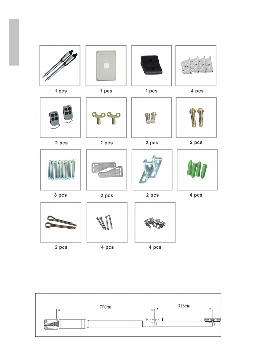
Included accessories
Description of swing gate opener

5User manual
English
1. Rear bracket
2. Front bracket
3. Extendable arm (300 mm)
4. Motor box
5. Power cable
Open the gate manually
1. Gates
2. Manual spanner
3. Piston motor
Release by spanner then lift it and separate the motor from the gates.

User manual 6
English
Functions
»In case of power failure: Use the manual spanner, separate the piston
motor from the gate and open or close the gates manually.
»When gate is obstructed: If, as they open, the gates encounter an
obstacle, they stop.
»Optional, the controller can be connected to a solar system, a warning
lamp, a photocell, a backup battery, an access keypad or other access
control devices.
»Speed control: the speed of opening / closing the gates can be adjusted.
»Gentle start: the system has a gentle opening function at startup.
»Auto closing:thesystemhasanautomaticclosingfunctionwithadjustable
closing time.
»Single or dual gates: the system can be installed on double or single gates.
»Multiple remote transmitters: the system supports several extra remote
controllers.
»Backup battery: a 24V backup battery can be connected (the backup
battery is not included).
»Smooth noiseless operation: the system can be configured for smooth
noiseless operation.
»The system can be configured to enable open condition as default, or
close condition as default depending on the placement of the provided
brackets.

7User manual
English
Technical specifications
Supply voltage 230VAC±10%
Motor voltage 24VDC 40W
Rotation speed 200 rpm
Maximum opening length
of the piston arm 300 mm
Piston elongation speed 1.6 cm/sec.
Maximum length of a gate 2.5 m
Maximum opening angle 110°
Continuous operating time 5 min.
Maximum weight of a gate 200 kg
Water protection class IP55
Working temperature -26°C ~ +60°C
Installation instructions
1. Remote control
2. Rubber stopper
3. Swing gate opener motor
4. Control unit
5. Photocell electric sensor
6. Gate opening warning light (optional)
User manual 8
English
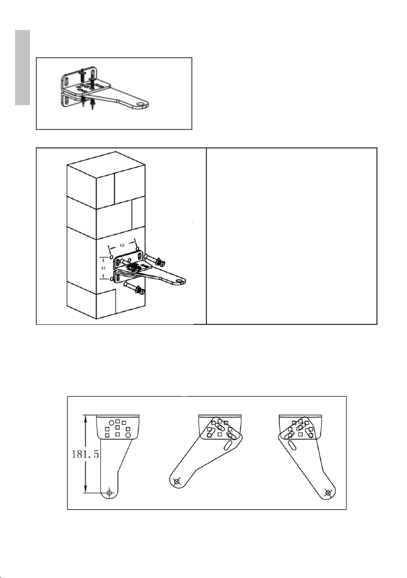
Rear brackets installation
• Make 4 holes in the wall of 8 mm
diameter.
• Insert 4 concrete bolts (included
in the package) into the holes.
• Position and secure with the
included screws the bracket for
the piston motor.
Note: If you have metal poles, you can
weld the brackets.
Adjusting dierent angles of rear bracket
9User manual
English
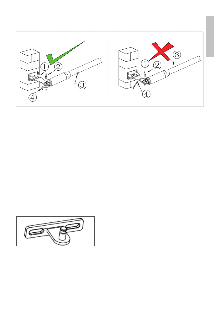
Warnings
Left image: the power cord and the drain hole are correctly positioned.
Right image: incorrectly positioned power cord and drain hole.
The power cord must not be above the engine body. In the opening motion
of the gate, the cable could be caught and pinched presenting a risk of short
circuiting.
1. Bracket
2. Lock pin
3. Drain hole
4. Power cable
Front brackets installation

User manual 10
English
1. Drill in the gate 2 holes of 10.2 mm each to a distance of 68 mm one
from each other.
2. Fix the bracket in the holes.
3. Fix the motor piston to the front bracket using screws (these are not
included as they vary depending on the thickness of the gate).
4. Insert the locking nut and the washers.
Brackets installation height
Make sure that the height of installation of the rear bracket is equal to the
height of installation of the front bracket. Performing an assembly based on
inaccurate measurements can lead to problems in the operation of the piston
arm. Also, the opening and closing force will be reduced. Large dierences
in height between the two brackets can even burn the motor and the piston
arm.
Table of contents
Languages:
Other PNI Gate Opener manuals


