Instr 9929139 Rev 01 2018-08 Page 9 of 13
WINCH OPERATION
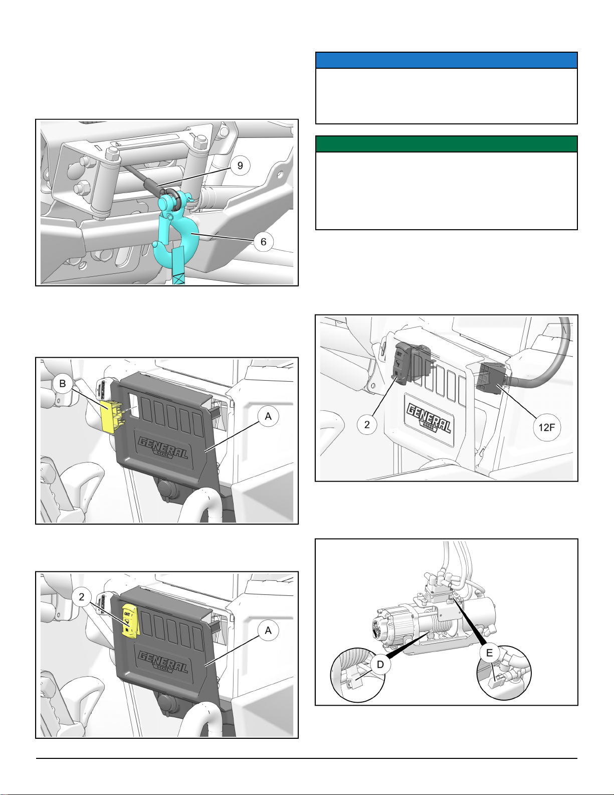
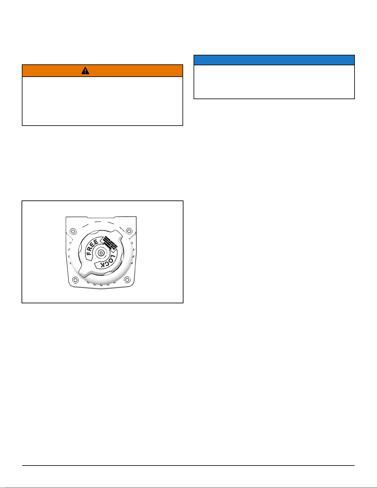
GEAR SELECTION
The Polaris 4500 HD winch is equipped with two
different gear settings. “FREE” and “LOCK”.
WARNING
DO NOT attempt to shift the winch while the rope/
cable is under tension. ALWAYS make sure the
winch rope/cable is not in tension before shifting the
winch between gears to avoid damage to the winch
mechanism. Failure to comply may lead to death or
serious personal injury
• The “FREE” setting is meant to be used to free-
spool the winch rope/cable for faster deployment.
To shift into “FREE”, rotate the gear selection
handle counter-clockwise.
• The “LOCK” position is meant to be used when
winching is required or to retract the cable/rope
back onto the winch spool. To shift into “LOCK”,
rotate the gear selection handle clockwise.
WIRELESS REMOTE OPERATION
(IF EQUIPPED)
NOTE
The remote will automatically turn itself off after 30
seconds of inactivity. You will therefore need to turn
the remote back on if it has been more than 30
seconds since the prior use.
• When properly installed, the wireless remote will
allow you to operate the winch from off the vehicle,
which can be a safe way to operate the winch when
done properly.
• To turn on the wireless remote, hold the small "On/
Off" button for three seconds or until the LED light
on the remote turns on. If the vehicle is on so that
the winch is receiving power, the wireless remote
should operate the winch as if you were using the
winch switch located on the handlebar. If the remote
is not operating properly, see the troubleshooting
information at the end of the instructions.
• To manually turn off the remote, hold the small "On/
Off" button for 3 seconds or until the LED light turns
off. The remote will automatically turn itself off after
30 seconds of inactivity.
• See the illustration below for proper wireless remote
operation.
AUTOSTOP OPERATION (IF EQUIPPED)
• The Autostop system is meant to help prevent
damage to the winch system from over-tightening of
the rope/cable, but is not meant to prevent all
foreseeable winch damage. The winch is very
powerful and care should be exercised whenever it
is in operation. The winch operator is always
responsible for using the winch properly and the
Autostop system should only be used as a
secondary preventive measure to help prevent
damage to the winch from over-tightening the rope/
cable.
• The Autostop system works when the black rubber
puck nears the aluminum fairlead. Stop magnets in
the puck trigger sensors in the fairlead, which
prevent the contactor from pulling in the winch rope/
cable any further. During final inspection, confirm
that the Autostop is functioning properly.
• Troubleshooting steps are given in that section to
help diagnose and correct any problems.