Polaris RANGER XP 900 CREW 6000 User manual

P/N 9926740 Rev 01 06/15 Page 1 of 12
BEFORE YOU BEGIN
Before you begin, read these instructions twice and check to be sure all parts and tools are accounted for.
Please retain these installation instructions for future reference and parts ordering information.
P/N 2881668
RANGER XP 900 CREW 6000 WINCH KIT
APPLICATION
RANGER XP 900 CREW
18
6
NOTE: You must order power cables separately to connect your battery to the vehicle bus bar.
•2879388: 3 Seat Models
•2879685: Crew Models
KIT CONTENTS
25
11
22
4
5
9
8
10
7
15
17
19 3
23
24 20
19
14
21
16
13
2
12
21
1

P/N 9926740 Rev 01 06/15 Page 2 of 12
IMPORTANT
Your Polaris RANGER XP 900 CREW 6000 WINCH KIT is exclusively designed for your vehicle.
Please read the installation instructions thoroughly before beginning. Installation is easier if the
vehicle is clean and free of debris. For your safety, and to ensure a satisfactory installation, perform
all installation steps correctly in the sequence shown.
TOOLS NEEDED
Standard and Metric Socket Set Standard and Metric Wrench Set Phillips Screwdriver
Drill and Drill Bit Set 1 1/16” Hole Saw or Drill
APPROXIMATE ASSEMBLY TIME
60 mins
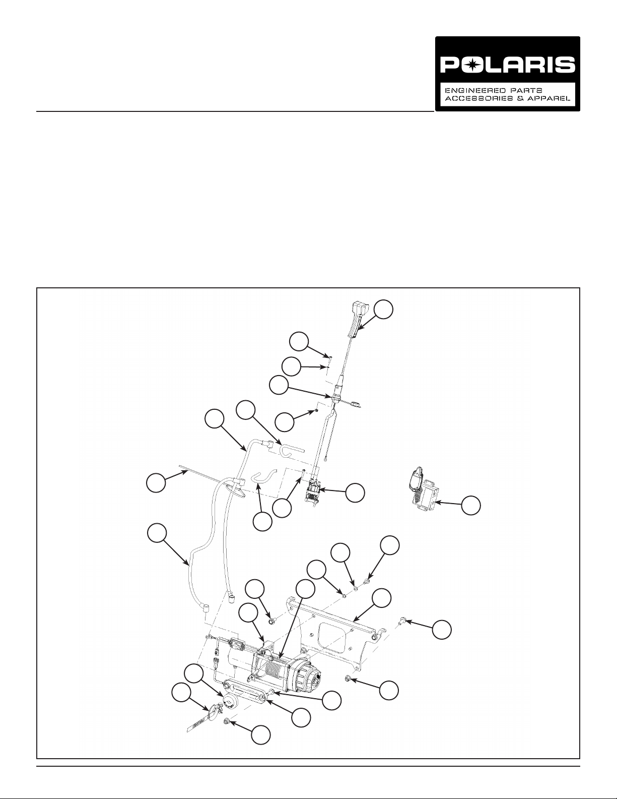
Ref Qty Part Description Part Number
1 1 Winch-POLARIS, 6.0 2204856
2 1 Hook-Latch, Winch 2412964
3 1 Rope Kit, Winch 2879188
4 1 Wireless Remote Winch 2879316
5 1 Contactor Winch 4015095
6 1 Remote Switch, Winch 4013466
7 1 Cable-Winch, Yellow, 6 GA, 800 MM 4013468-800
8 1 Cable-Winch, Blue, 6 GA, 800 MM 4013469-800
9 1 Power Cable, Winch, Black 4013470-250
10 1 Power Cable, Winch, Red 4013471-250
11 1 Remote Socket - Winch, Long 4014228
12 1 Fairlead, Wide, Mach *KIT 2881692
13 1 Magnet Stop, Rubber Bumper *KIT 2881692
14 1Mount Winch, 4500 5439929
15 10 Panduit Strap 7080492
16* 2 Screw-HXFL - M10 X 1.5 X 30 -
17* 4Screw-#10 - 32 X 1 -
18* 2Screw-M5 X 0.8 X 20 -
19* 4Screw-M10 X 1. 5 X 25 -
20* 4Screw-HXFL M8 X 1 .25 X 25 -
21* 4Nut-M10 X 1.5 -
22* 2Nut-M5 X 0.8 -
23* 4M8 Lock Washer -
24* 4Washer-0.62 X 0.330 X 0.060 -
25* 2M5 Flat Washer -
1Winching Guide 9923644
1 Instructions 9926740
ITEMS MARKED (*) ARE INCLUDED IN HARDWARE KIT PN 2879172.

P/N 9926740 Rev 01 06/15 Page 3 of 12
INSTALLATION INSTRUCTIONS
1. Turn key to “OFF” position and remove key from
vehicle. Remove front and rear seats. Disconnect
black negative cable from battery. Disconnect red
positive cable from battery.
2. Removehoodfromvehicleasshowningure.
3. Removefourpushdartsfastenersfromcenteroor
section. One on each side by foot pedal as shown
ingures.Savefastenersforreinstallation.Remove
centeroorsection.
Push Dart
One Each
Side
4. Lift out seat and pullout tray on passenger side as
showningure.
Push Dart

P/N 9926740 Rev 01 06/15 Page 4 of 12
CONTACTOR AND WIRING INSTALLATION
1. Install red and black power and ground cable (sold
separately, see Page 1) by sliding under seat where
centeroorsectionwasremovedandrouteupto
battery by following the main wire harness. DO NOT
connectatthistimeasshowningure.
On crew models, route hoses through the tunnel
areaundertherearoorsectionandintothearea
under the rear seat.
2. Slide the other end of cable through bulkhead.
Follow main wire harness up and onto the splash
trayasshowningure.
3. Connect short (250 mm) red and black cables to the
bus bar on the same posts as the wires previously
connected. Reinstall nuts on bus bar. Connect wires
to red and black terminals on contactor and lightly
tighten. DO NOT OVER TIGHTEN. Slide the cable
coversonasshowningure.
Orange
(Key power)
Brown
(Ground)
Red/White
(Battery +)

P/N 9926740 Rev 01 06/15 Page 5 of 12
4. Install contactor with Phillips screws/screwdriver in
thehoodsplashtrayasshowningure.
5. Connect red cable to red colored post on contactor
and tighten with a 10 mm wrench. Connect the black
cable to the black coded post and lightly tighten. Do
not over tighten. Slide the cable covers on as shown
ingure.
WINCH INSTALLATION
1. Install mount plate to winch with 1” (25 mm) bolts
and lock washers. Finger tighten then tighten with a
13mmsocketasshowningure.
2. With a 15 mm wrench and socket remove the four
bolts (two on top; two on bottom) that hold on the
front bumper. Lift off front bumper. Retain hardware
forreinstallationasshowningure.

P/N 9926740 Rev 01 06/15 Page 6 of 12
3. Line up holes in front of machine to mount winch.
IMPORTANT: Nuts not required for top two bolts.
Installfourfasteners(1.5”longnylockangehead
bolts and nuts) with a 17 mm socket and 15 mm
wrench. Torque to 25 ft. lbs. (33.8 Nm) as shown in
gures.
4. Connect yellow and blue cables to the
corresponding post on winch with a 10 mm wrench.
Push cables up through the splash tray and to
contactorasshowningure.
5. Install roller fairlead or auto stop fairlead if your
vehicleisequippedasshowninguretofront
bumper with two bolts. Tighten with 8 mm Allen
wrench and 17 mm socket.
IMPORTANT: If your vehicle is equipped with
the auto stop fairlead, see Page 11 for additional
information on function of this feature.

P/N 9926740 Rev 01 06/15 Page 7 of 12
6. Tighten Auto Stop fairlead with 8 mm Allen wrench
and15mmsocketasshowningures.
8. Connect the yellow and blue winch wires to
contactor and push cable covers on as shown in
gure.
7. Reinstall front bumper with fastener removed
earlier. Make sure the winch cable or rope is
throughthefairleadslotasshowningure.

P/N 9926740 Rev 01 06/15 Page 8 of 12
REMOTE SOCKET INSTALLATION:
Washer Bottle
Approximate
Grommet Location
2. Locate the area where the wire harness and hose
will pass through the front dash wall. On MY13
vehicles a grommet is already installed. For MY14
it is a round area of 1 11/16” diameter that must be
removed by cutting along the perimeter scribe line
with a sharp tool. Remove the round plastic cut out
asshowningure.
3. Install the grommet (PN 5414440).
IMPORTANT: Vehicle hardware kit contains the
grommet.
4. Cut the grommet (PN 5414440) to allow wire
harness through.
1. Install remote switch on vehicle dash. Use a
1 1/16” drill bit to cut a hole centered between
dots embossed on dash. Drill two holes for screws
with 1/4” drill bit over embossed dots as shown in
gures.
1 1/16” Hole
1/4” Hole

P/N 9926740 Rev 01 06/15 Page 9 of 12
FINAL INSTALLATION:
1. Auto Stop Fairlead: Slide on rubber stop, Polaris
logo showing. Attach winch hook with cotter pin to
rope.
2. Attach red cables to battery to the battery side of
starter solenoid. Attach black ground wire to ground
post. After wires are connected, panduit power and
ground cables to the main wire harness to keep
clear of moving parts and panduit to frame.
5. Push the wires back through the grommet and
replace grommet in upper splash tray hole.
Connect black wire to connector and red wire to the
keyed power terminal. After wires are connected,
panduit power and ground cables to the main wire
harness to keep clear of moving parts and panduit
toframeasshowningure.
6. Attach switch with the two Phillips screws, washers
and nuts provided in kit. Install in this order, screws,
switch housing, dash, washer, nut. Tighten with a
Phillips screwdriver and a 8 mm wrench as shown
ingure.
Grommet

P/N 9926740 Rev 01 06/15 Page 10 of 12
9. Verifyfunctionofwinchasshowningure.
10. Conrmthattherearenoexposedwiresor
terminals. All loose wires need to be wrapped tight,
and secured away from moving parts and heat
sources.
11. Reinstall pullout tray under seat.
12. Reinstall seats.
13. Retighten all hardware after 30 minutes of riding.
5. Re-connect the main vehicle power cables and
winch power cables to the battery using the original
hardware.
6. With the vehicle key in the ON position, check
winch for proper operation.
7. Conrmthatallwiringiscorrect.
8. Connect winch remote control to electrical socket
asshowningure.
3. Secure cables to frame and main wire harness.
4. Replacethecenteroorsectionandreusethefour
push guard pins removed at a earlier step.

P/N 9926740 Rev 01 06/15 Page 11 of 12
Function of the Auto Stop Feature:
The Auto Stop fairlead is an innovative solution making your winch easier to use, especially when plowing. The
hardest work your winch does is when it isn’t doing much work at all; when your winch pulls the rope tight to
get the last bit of lift out of the plow or to tighten up the hook to prevent it from rattling against the bumper. As
the winch pulls the hook against the fairlead it stresses the winch, rope, fairlead, and vehicle frame. To help
prevent damage to these components, Polaris created a solution that stops the winch before the hook is pulled
too far into the fairlead.
If your vehicle is equipped with this feature it contains an aluminum Hawse-type fairlead, a rubber bump stop
that contains magnets, and a wire harness with a control box. This winch is only for use with synthetic rope, as
a steel cable would quickly wear and damage the aluminum fairlead. When the rubber bump stop is brought
close to the fairlead, sensors inside the fairlead tell the control box to turn the winch off. The winch will continue
to let rope out, but the rope will not pull in any further.
1. To assemble, install the aluminum Hawse fairlead
in the same location as the standard roller fairlead
would be, using the same hardware. Wire routing
will be simplest if the wires are located on the
passenger side of the vehicle. Place the control box
close to the winch contactor and extend the longer
wire toward the fairlead. Disconnect the remote
control from the winch contactor, and plug those
two connectors into the corresponding connectors
on the control harness. Once the connections have
been made, route the red and black wires to the
terminal block. The black wire must be connected
to a solid ground, and the red wire should be
connected to keyed power so that the winch will
only operate when the vehicle key is turned to the
ONpositionasshowningure.
2. Disconnect the remote control from the winch
contactor, and plug those two connectors into the
corresponding connectors on the control harness.
Control Box
Connectors

P/N 9926740 Rev 01 06/15 Page 12 of 12
4. Thread the winch rope through the fairlead, then
thread the rope through the rubber bump stop
with the “POLARIS” label facing outward toward
the front of the vehicle. The rubber bump stop is
supposed to be tight on the rope, so use a string
or plastic cable tie tied around the end of the rope
to pull the rope through the bump stop. It is helpful
to apply a small amount of rubbing alcohol or other
non-corrosive lubricant to the rubber stop to ease
the rope through the hole. Once the rope is through
the hole, attach the hook to the rope with the cotter
pinasinstructedinthewinchkitasshowningure.
5. Beforeuse,conrmtheproperfunctionoftheAutoStopbyturningonthewinchandspoolingitin.The
rubber stop should get close to the fairlead and the winch should turn off automatically. If it does not, check
that all connections are made properly and that the rubber stop is facing with the “POLARIS” side facing
outward and re-test.
The Auto Stop system is meant to help prevent damage to the winch system from over-tightening of the rope,
but is not meant to prevent all foreseeable winch damage. Keep in mind that the winch system is very powerful
and care should be exercised whenever it is in operation. The winch operator is always responsible for using
the winch properly and the Auto Stop system should only be used as a secondary preventive measure to help
prevent damage to the winch from over-tightening of the rope.
3. Once the connections have been made, route the
red and black wires to the wire harness. The black
wire must be connected to a solid ground, and the
red wire should be connected to keyed power so
that the winch will only operate when the vehicle
keyisturnedtotheONpositionasshowningure.
POLARIS-Label
Table of contents
Other Polaris Winch manuals