POMI Kombi-Pack User manual

Abildvadvej 5, Thorup
DK-9610 Nørager
Denmark
Tlf.: +45 98552000 Fax +45 98552200
E-mail: [email protected]
Web side: www.pomi.dk
English

2
Contents
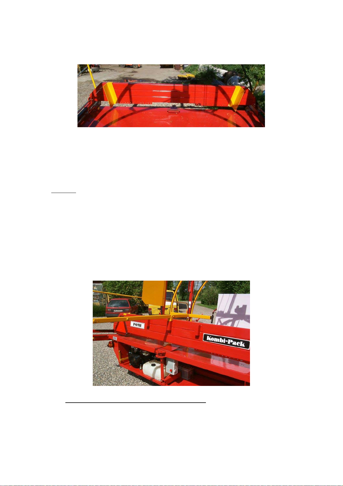
1. POMI KOMBI-PACK WRAPPER........................................................................................................... 3
2. PRECAUTION ............................................................................................................................................ 3
3. EU DECLARATION OF ACCORDANCE............................................................................................... 4
4. IDENTIFICATION OF THE MACHINE................................................................................................. 5
5. SOME ADVISE BEFORE STARTING WRAPPING SILAGE.............................................................. 5
6. BEFORE START ........................................................................................................................................ 5
7. REARRANGEMENT FROM TRANSPORT TO WRAPPING............................................................. 6
8. WRAPPING................................................................................................................................................. 6
WRAPPING OF SILAGE.................................................................................................................................... 6
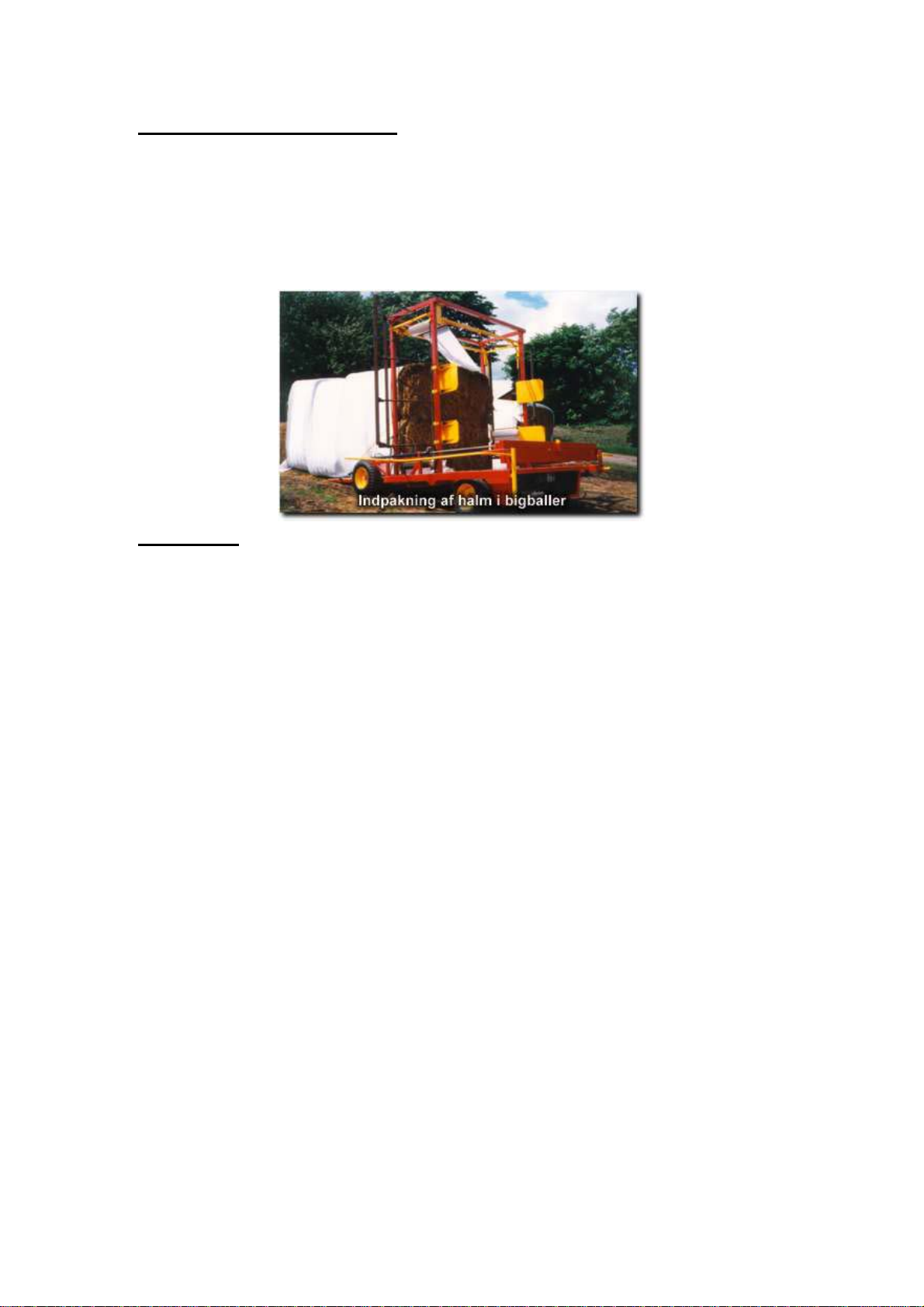
WRAPPING OF STRAW,BIG-BALES WITH AMMONIAC ................................................................................. 6
WRAPPING OF MINI-BIG-BALES WITH AMMONIAC ...................................................................................... 6
WRAPPING OF STRAW FOR STORAGE ........................................................................................................... 6
9. CLOSING..................................................................................................................................................... 7
10. CHANGE FROM SILAGE OVER TO STRAW WRAPPING.......................................................... 7
11. ADJUSTING OF THE SENSORS ........................................................................................................ 8
12. ADJUSTMENT OF THE SUPPORT UNDER THE BALES............................................................. 8
13. CHANGE OF FOIL ROLLER.............................................................................................................. 8
14. FUNCTION OF THE MACHINE......................................................................................................... 9
14.1. ELECTRICAL BOX................................................................................................................................... 9
14.1.1. EL-DIAGRAM –BOX.......................................................................................................................... 10
14.1.2. ELECTRIC DIAGRAM –JUNCTION BOX............................................................................................... 11
14.2. REMOTE CONTROL.............................................................................................................................. 12
14.3. HYDRAULIC SYSTEM .......................................................................................................................... 12
14.4. FILM GUARD........................................................................................................................................ 12
15. MAINTENANCE.................................................................................................................................. 13
16. EQUIPMENT IN OPTION.................................................................................................................. 14
16.1. ROUND BALES EQUIPMENT.................................................................................................................. 14
16.2. HYDRAULIC RAISING OF THE FRAME.................................................................................................... 15
16.3. SILAGE BOX......................................................................................................................................... 16
16.4. EQUIPMENT FOR SILAGE...................................................................................................................... 16
16.5. RACK FOR BOTTOM FOIL...................................................................................................................... 17
16.6. BASKET FOR ROLLS OF FILM ................................................................................................................ 17
17. PROBLEMS.......................................................................................................................................... 18
Updated 13.06.2000

3
1. Pomi Kombi-Pack Wrapper
Congratulation – You have chosen a sausage-wrapping machine, only to be used for wrapping
silage and straw. If required used for any other product you will need the manufacturer’s
written authorization.
The bales are set onto the machine the bar pushes the bales into the wrapping unit. Foil is
wrapped around the bales making a long sausage.
2. Precaution FOR YOUR SAFETY!
Always make sure that the motor is stopped and the emergency button is activated before
effectuating any work on the machine.
Unauthorized persons are not allowed within a distance of 10 m from the machine when in
operation, partly due to the sudden movements of the machine and partly due to the fact that
oil may suddenly spray from a damaged hose. At the same time there is a risk that the first
bales coming out of the machine might tip over.
The yellow shackles must be down during operation.
Make sure that nobody is present that might get under the rear flap when being lowered.
One might be squeezed at the bar. Warning signs are fitted onto the bar.
The tower must be lowered when being on the road, if a hydraulic lift is fitted.
Keep the machine clean, especially around the motor to avoid fire risks. Spillage of oil in the
motor compartment must be cleaned before the motor is restarted.
The pull is checked for damage. The cotter bolt is locked with split-pin.
Light must function according to the Road Traffic Act.
Make sure that the remote control is positioned at a safe place so that you do not by accident
push one of the buttons. E.g., if the remote control is in a pocket when changing the foil roller
then leaning against the machine, you might push one of the buttons, starting the machine.

4
3. EU declaration of accordance
Manufacturer: POMI ApS
Abildvadvej 5, Thorup
DK-9610 Nørager
Tel. 0045 98552000
Company
hereby declares that
Machine: Wrapper machine
Make Type, series no., year
a) is manufactured in accordance with decisions made in the Council’s Directive of 14th
June 1989 about mutual approach of the member states’ legislation as regards
machines (89/392/EØF) changed on 20th
June 91 (91/368/EØF) (93/44/EØF) and
(93/68/EØF), under special reference to exhibit I of the directive of severe safety and
health requirements in connection with design and manufacturing of machines.
Especially:
b) is manufactured in accordance with the following harmonized standards (Directive
article 5, paragraph 2).
c) is manufactured in accordance with other standards and/or technical specifications.
_____________________________ ________________________
Signature Date
Poul Mikkelsen
Manager
POMI ApS

5
4. Identification of the machine
When ordering spare parts, make sure to give the serial number of the machine. This is written
on the left side of the machine, as shown on the picture below. The motor’s number is written
on its left side.
Serial number: __________________
Motor number: __________________
5. Some advise before starting wrapping silage
Plan the mowing time so that it is possible to have a total solids percentage of app. 50%.
Make sure the bales are made accurately, firm in both bottom and top.
Move the bales as little as possible in order to keep the shape.
6. Before start
Tank fuel.
Check that the hydraulic oil is at the middle of the glass on the tank.
Go through the manual for the motor before starting and heating of the motor.
Revolutions are set at max. 2800.

6
7. Rearrangement from transport to wrapping
A tractor drives the machine in correct position so that the machine stands where the stack
must be.
Unhitch the tractor and remove the light wire.
Check the distance between sensors (see section 11) and adjust the support beneath the bales
(see section 12).
Put down the guarding shackles.
Press the emergency stop push-button.
Start the motor according to the manual.
Switch the emergency stop out of lock position.
Lift the rear flap (see hydraulic section 14.3). The tractor pull is removed and the rear flap is
lowered. Make sure that nobody stands behind the rear flap when lowering.
Lubricate the plastic plate with silicone.
Lift the machine on the supports so that the first bales are not sliding out of the machine.
The machine is ready.
8. Wrapping
Wrapping of silage
Place end plastic on the bale it is easy done when the bale hangs on the front
loader, then place the bale in the machine.
When 5 bales are on the ground behind the machine the machine is braked to push
the bales together (the hand brakes are at the front wheels).
Wrapping of straw, big-bales with ammoniac
First position a bale in the machine, and then 2 bales are positioned on top of each
other with end plastic.
Wrapping of mini-big-bales with ammoniac
First one bale is positioned in the machines then 2 bales, and then 3 bales with end
plastic are positioned.
Wrapping of straw for storage
As described above, however it can be done without the end plastic.

7
It is important that the bales are positioned between the two yellow plates on the bar in order
to be guided in position.
When the bales required wrapped are at the wrapper section, then start wrapping 10 laps
around the bale to fix the plastic. More bales are fed into the machine, please check that the
required layer of plastic is wrapped around the bale. Then the machine can be switched into
automatic mode. Change of foil rollers (see section 13).
9. Closing
When the last bale is positioned on the machine the machine runs till it reaches the foil. Then
the bar is moved back and the bale is lifted with the front loader so that the end plastic can be
pulled beneath it. The bale is lowered and tractor and front loader is removed. The plastic is
wrapped around the bale and fixed with tape. The first push out pole and bracket is fixed (see
illustration below) and the wrapping is finished. Tear off the foil when going up the stack and
push the last bales out. When the first push out pole cannot reach anymore the second pole is
fixed.
Remember! If you have a hydraulic lift the tower must be lowered before road transport.
10. Change from silage over to straw wrapping.
Detach the chain and make it longer with the extension piece delivered together with the
machine. Take the silage equipment off. Put the chains on the rails of the tower and tighten
them.

8
11. Adjusting of the sensors
The sensors for the bar must be adjusted so that the distance between sensor 2 and 3 is equal
to the width of the bale. The distance between sensor 2 and 1 must be set so that space for
entering the bale in position is sufficient.
12. Adjustment of the support under the bales.
The support under the bales must be adjusted
in that way that the support plate is placed 2-4
cm above the rolls.
13. Change of foil roller
Make sure that the foil roller holder is positioned so that you can reach it.
Push the emergency stop.
Change the foil roller
Switch off the emergency stop
3
2
1

9
14. Function of the machine.
14.1. Electrical box
Emergency stop.
A simple pressure on this contact stops all functions in the electrical box. To start again, turn
it out of its lock position and activate the needed function.
Ready
A release from the emergency stop and the lamplights up showing that everything is ready.
Start
This contact starts the wrapping program. Another pressure on the contact to stop the
program.
Forward
A pressure on this contact and the pushing bar moves forward.
Backward
A pressure on this contact and the pushing bar moves backward.
Film
A pressure on this contact and the film wrapping starts.
Auto
A pressure on this contact, the lamp lights up and the machine starts the wrapping as soon as a
bale is put on the table. Another pressure and it stops.
Left
The machine turns to the left.
Right
The machine turns to the right.

10
14.1.1. El-diagram – Box

11
14.1.2. Electric diagram – Junction box

12
14.2. Remote Control Red is the same as start
Grey is the same as film
Green is the same as left
Yellow is the same as right
14.3. Hydraulic system
Before the machine, there is a flow regulator, one ball valve and 2 or 3 hydraulic handles. The
flow regulator is to adjust the speed of the pushing bar, which means at the same time to
adjust the plastic quantity needed. Open the ball valve to empty the machine, and the pushing
bar is then thrown forwards at a high speed. The first hydraulic handle is to pull the rear door
down, which has a lock system, and to give it then a floating position when down. The second
hydraulic handle is to get the legs down. The third hydraulic handle is to adjust the high of the
frame (Hydraulic lift, see section 14.2).
The hydraulic oil used is Hydro Texaco HD Z LT 46 DIN HLP 46.
Hydraulic pressure: pushing bar 210 bar
Wrapper 150 bar
14.4. Film guard
A film guard is placed under the support plate; it
is consisting of a bar, which is touching the
wrapped film at the place where there is only one
lay. If the film brakes, the bar will fall down,
activating a contact, which stops the machine.
The machine re-starts with one pressure on the
remote control, keeping the finger on the button
until the film guard is in contact with the film.

13
15. Maintenance.
Clean the motor compartment daily or when needed to avoid fire.
Bearings are lubricated with grease daily.
Bar and chains are lubricated with chain oil.
When changing chains, please only use original chains.
After day one the wheels are tightened after that 2 times a year.
Revolutions = 100 Nm
15.1. Checkpoints before season start
The machine is stopped and the emergency stop is activated.
Oil change
Change of oil filter
Change of fuel filter
Change of air filter
Change of hydraulic filter
Check the hydraulic oil level
Pre-stretchers
Wrapper chains are tightened
Check the distance between the chain rails
(Machine W = 1177 mm / Round bale unit W = 928 mm).
Pull chains for wrapper is tightened
Wheels are tightened. Revolutions = 100 Nm
Pull is checked for damage
The machine is started.
The foil watch is tied.
Electric box and remote control are checked on all channels.

14
16. Equipment in option
16.1. Round bales equipment
Before mounting the equipment for round bales, dismount the steering brackets from the top
of the unit as well as spear and support plate. The stretching roller must be correctly placed
(see below picture).
With the help of the front loader, raise the unit above the rear-door and put it down on place,
screwing it fast. Move the hoses from the machines’ oil motor to the round bales’ equipment.
Mount the spear, the support plate and the steering brackets on again.

15
16.2. Hydraulic raising of the frame
When the frame is up, adjust the bolt of the threaded bar in that way that the chains are
tightened just at the moment where the pistons are pressed at the top.
8 bolts are necessary to fix the chains when sinking the frame. Get the stretching rollers into
the position shown on the below picture. Fix the 4 bolts at the bottom. Pull the frame down
and fix the 4 bolts at the top.
The frame must be pulled down during the transport.
Bolte

16
16.3. Silage box
This box is needed when superposing 2 bales in silage wrapping. The idea is to get the film
around the bales to create a barrier avoiding the air to penetrate the stack.
16.4. Equipment for silage
The equipment for silage is composed of 2 bars as shown on the picture. They can be mounted
at two different highs on the frame. The winding chain is placed above the bars and it is
shorted to give the same length to the 3 chains.

17
16.5. Rack for bottom foil
Consist of 2 holders placed on the pushing bar giving space to a roll of film in between. The
film is carried under the pushing bar, over the support plate, the rolls and the rear-door.
16.6. Basket for rolls of film
The basket can take approx. 15 rolls and 1 roll of end plastic
Inner measure: 1000 x 1100 mm - High = 620 mm
To be placed on the machine with the help of a front loader. The two angle supports are to be
hooked over the pushing bar.

18
17. Problems
Problems
Solution
Machine
The motor does not pull out
−Remove the fuel filter
−
Remove the air filter
The pushing bar doesn’t push the bales
−
Check the hydraulics (210 bar)
The driving chain brakes
−
Make sure that the safety rails have the
correct distance.
Machine W=1177 mm
Round bale unit W=928 mm
−
Mind the chain travel at the bottom
The wrapper stops
−The bales are too big
−Check the oil pressure (150 bar)
−The chains are not lubricated
−The chains are too tight
−
The chains are out of their rails
Straw
Holes in the plastic, at the bottom
−Not enough silicone on the plastic surface
−The spear supporting the bales under the
wrapping are too low (see instructions)
Humidity at the bottom of the stack
−
Use more bottom plastic
Humidity on the top of the bales
−
The straw must be dry and mature before
pressing and wrapping
−Making holes in the sides could help
−The soonest the straw is used, the less
problems. We recommend that the straw
is used before mid April.
Ensilage
Moistness between and on the bales
−The bales are not pushed against each
others; brake the machine
−Use more plastic around the bales
−Too small consumption of the stack
−Cut the grass at the right time
−Press the bales to make them firm
−If the bales are not pressed hard enough,
throw some earth on the stack to press the
air out of it
The bales are moist before the opening of the
stack
−
Use more plastic around the bales
−Close the ends with some scotch
−Cut the grass at the right time
−Sift some sand along the stack to avoid
mouths and other vermin to dig under

19
Problems
Solution
2 superposed silage bales
Moistness at the end of the stack
−
Make an end cap with some plastic and
scotch it.
Moistness on the bales when picking up the
first bales of the stack
−It is possible to put some end pieces
between the bales when wrapping
−It is possible to choose to put only one
bale instead of two
−Use the silage box to avoid the air to
penetrate the stack sideways.
Table of contents
Other POMI Farm Equipment manuals