POMI Stack 200 User manual

2
Table of Contents
1. POMI STACK 200......................................................................................................................................... 3
2. SAFETY INSTRUCTIONS ............................................................................................................................... 3
3. EU DECLARATION OF CONFORMITY.............................................................................................. 4
4. MACHINE IDENTIFICATION......................................................................................................................... 5
5. COMPUTER .................................................................................................................................................. 6
6. SENSOR OVERVIEW...................................................................................................................................... 7
7. BALE STACKER START-UP........................................................................................................................... 8
8. THE HYDRAULIC SYSTEM.......................................................................................................................... 10
8.1. THE TRAILER VALVE BLOCK ................................................................................................................ 10
8.2. VALVES IN THE CONTROL BOX/TOOLBOX............................................................................................. 10
8.3. HYDRAULICS DIAGRAM....................................................................................................................... 11
9. ELECTRIC BOX........................................................................................................................................... 13
9.1. WIRING DIAGRAM ............................................................................................................................... 15
1. TECHNICAL SPECIFICATIONS.................................................................................................................... 22
Revised on 29.05.2019

3
1. Pomi Stack 200
Thank you for choosing the Stack 200 bale stacker from POMI for your straw and silage
needs.
Using the bale stacker for any other purposes is subject to prior written permission from the
manufacturer.
2. Safety instructions
FOR YOUR OWN SAFETY
Only carry out work on the machine when the tractor has been stopped and the
emergency stop on the electric box has been activated.
Do not allow unauthorized personnel within a distance of 10 m from the machine
when it is in operation as the machine can make sudden movements and oil may
squirt from a damaged hose.
The lights must be functioning in accordance with national traffic regulations. It
is the operator’s responsibility to ensure that the lights meet current national
legislation.
Drive sensibly when using the bale stacker, as reckless driving will damage the
trailer. POMI assumes no liability for any damage caused.
Special care should be taken when setting the oil flow speed, as too much oil may
cause the tractor to overheat and consequently damage the tractor. POMI
assumes no liability for any such damage.
Remember to re-tighten the wheel and the wheel axle

4
3. EU DECLARATION OF CONFORMITY
Manufacturer: POMI Industri ApS
Abildvadvej 5, Thorup
DK-9610 Nørager
Tlf. +45 98 55 20 00
Company
Hereby declares that
The following machine: Stack 200
Make type, serial no., year
has been manufactured in conformity with the provisions of Council Directive 2006/42/EEC
of 17th May 2006 on the approximation of the laws of the Member States relating to
machinery, with particular reference to its Annex II, A and Annex I on essential health and
safety requirements for the design and construction of machinery.
The machine has been manufactured in conformity with the following national/international
standards and technical specifications
DS/EN ISO 12100-1:2005 Safety of Machinery - Basic concepts and general principles for design - Part 1:
Basic terminology and methodology.
DS/EN ISO 12100-2:2005 Safety of Machinery - Basic concepts and general principles for design - Part 2:
Technical principles.
DS/EN ISO 13857:2008 Safety of Machinery - Safety distances to prevent hazard zones being reached by
upper and lower limbs.
Nr. 693 Executive Order of 10 June 2013 issued by the Danish National Working Environment
Authority, Arbejdstilsynet. Executive Order on the Design of Technical Equipment.
Signature Date
Poul Mikkelsen
Managing director
POMI Industri ApS

5
4. Machine identification
When ordering parts, please state the serial number of the machine. You will find the serial
number on the left side of the machine, as shown in the picture below.
Serial no.___________________

6
5. Computer
1 2 3 4 5 6 7
8 9 10 11 12
1. Start/pause (the external button has the same function).
2. Menu
3. Bale clamp out/in
4. Tip the bale onto the loading platform.
5. Lift the loading platform up and down / tip the bales onto the trailer.
6. Tilt the trailer
7. Move the stacker forks forward/backwards depending on the amount of bales stacked on
the trailer.
8. Move the drawbar to the right/the left.
9. Move the support wheel located in the front right corner up/down.
10. Move the left side in/out.
11. Move the right side in/out.
12. Bale push-off

7
6. Sensor overview
This is an overview of the sensors on the Stack 200.

8
7. Bale stacker start-up
Use the start button to start and pause the loading
program. Press this button to start automatic
loading. The external button ( 1 ) has the same
function.
Use the Menu to choose between the two loading
programs. Choose the loading program where the
bale clamp starts in the inner position or the other
program where the bale clamp starts in the outer
position. By pressing the start button when the bale
clamp is in the inner position, the bale clamp comes
out. You use this for turning the bale. When
pressing the start button a second time, the
loading program will start.
By pressing Menu, you can switch the program so
the bale clamp starts in the outer position. Press the
start button to start the loading program.
When the loading program starts, the bale clamp
compresses the bale until reaching the compression
pressure set in the PLC. The bale is then lifted
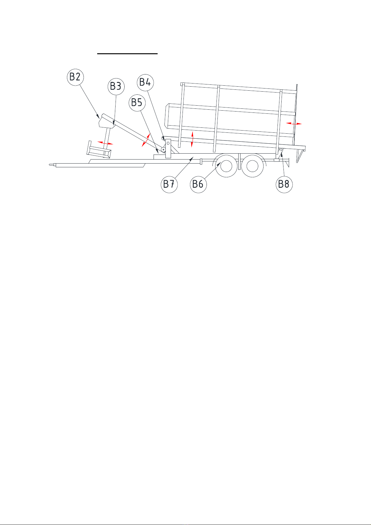
upwards until sensor B2 is activated.
In this position the bale clamp releases the bale
when the set pressure is reached. The fork yoke then
moves downwards until sensor B3 is activated, and
the trailer is ready to receive the next bale.
1

9
When the loading platform is full, it tilts
upwards until sensor B4 is activated. It is then
lowered until it reaches sensor B5. When the
loading platform stops in the top position, the
trailer is full. It is therefore important to enter in
the PLC how many layers and stacks you want
to load onto the trailer. See the section on the
electric box.
The push-off mechanism cannot be used, if the trailer is not tipped upwards and sensor B8 is
activated.
The push-off mechanism must be pulled in and sensor B6 must be activated before the trailer
can be tilted up or down.

10
8. The hydraulic system
8.1. The trailer valve block
Use the hex screw ( 1 ) to adjust the oil flow when using a load sensing control system (LS).
The pressure control valve ( 2 ) is set to 180 bars.
8.2. Valves in the control box/toolbox
When using an LS control system, the hex screw ( 3 ) must tightened and when not using an
LS control system (hydraulic circulation) it must be loosened.
1
2
3

11
8.3. Hydraulics diagram
Left side
Right side
Drawbar
Retention fork
Bale push-off
mechanism
Bale clamp
(master/slave system)

12
Tilt trailer
Tilt loading platform
Support wheel
Bend fork yoke
Blocking of suspension

13
9. Electric box
In the PLC on the electric box you set how many
layers and stacks you want to load onto the trailer.
Here you also set the closing and opening time for
the bale clamp.
If you need to change any of the values, press and
hold the ESC button until a row lights up.

14
Then, using the up and down arrows, move to the
row you want to change and press OK.
Then there is only one number marked where you
can move the selection with the left/right arrows,
and change the value with the up/down arrows.
Press OK, and exit by pressing the ESC-button.

15
9.1. Wiring diagram
Sensor Tilt fork yoke UP
Sensor Tilt fork yoke DOWN
Sensor Tilt loading platform UP
Sensor Tilt loading platform DOWN
Sensor Bale push-off
Sensor Tilt trailer
Start/Pause
Change program
Sensor Pressure

16
Bale clamp CLOSE
Bale clamp OPEN
Bend fork UP
Bend fork DOWN
Tilt loading platform UP
Tilt loading platform DOWN
Tilt trailer UP
Tilt trailer DOWN
Retention fork forward
Retention fork backwards

17
Drawbar IN
Drawbar OUT
Support wheel DOWN
Support wheel UP
Left side DOWN
Left side UP
Right side UP
Right side DOWN
Bale push-off mechanism IN
Bale push-off mechanism OUT

18
Bypass valve
Bale clamp CLOSE
Bale clamp OPEN
Retention fork
Retention fork reflux valve
Tilt trailer UP
Tilt trailer DOWN
Tilt trailer UP

19
Tilt loading platform DOWN
Bend for yoke / Tilt fork yoke UP
Bend for yoke / Tilt fork yoke DOWN
Bale push-off mechanism OUT
Bale push-off

20
Drawbar IN
Drawbar OUT
Support wheel DOWN
Support wheel UP
Left side DOWN
Left side UP
Right side UP
Right side DOWN
Bale push-off mechanism IN
Bale push-off mechanism OUT
Bale
push-off
Table of contents
Other POMI Farm Equipment manuals
Popular Farm Equipment manuals by other brands

Hardi
Hardi COMMANDER 4500 Operator's manual

enorossi
enorossi RAKE CADDY Series User and maintenance manual

Brouwer Kesmac
Brouwer Kesmac 4000 R Series Operator's manual

Rauch
Rauch AXIS EMC ISOBUS Original instructions

Amazone
Amazone Precea 9000-TCC Original operating manual

AGRIMASTER
AGRIMASTER GL 60 Use and maintenance manual