Porta KIS100 User manual

KIS100
Power Gate Operator
Installation Manual
Table of Contents
Introduction............................................. page 1
Technical Specifications......................... page 2
Installation Mechanical............................page 3
Installation Electrical............................... page 5
Electrical Schematic................................page 6
Troubleshooting..........................….........page 7
Emergency Power Connections..…....... page 8
PATENT PENDING
Porta Inc. Phone: (847) 593-4900
2420 Hamilton Rd. Fax: (847) 593-1394
Arlington Heights, IL 60005 website:emiporta.com

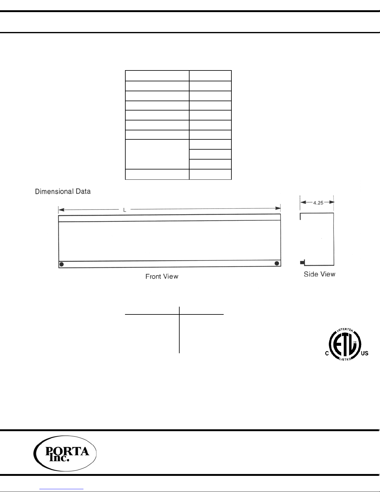
Page 1 KIS100 Power Gate Operator
Introduction
The KIS100 gate operator is a proven product that provides a user friendly, dependable and
cost effective means of automating accordion gates used in residential and LULA elevators.
It has passed an accelerated life test of 25 years of normal residential use (100,000 cycles).
This product conforms to UL508A, ASME A17.1A, ASME A17.5, CSA-B44-94, and CSA-
C22.22, No. 14-M91.
Features & Benefits
• Two Speed bi-directional gate operation
• Selectable Auto-Close feature
Will automatically close the gate when the open signal is removed
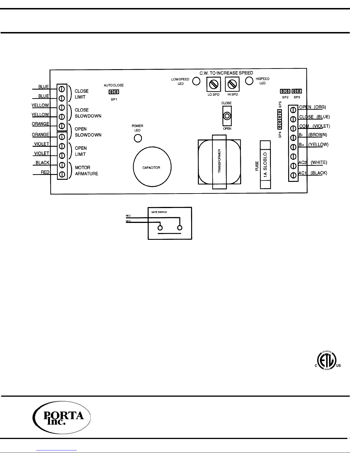
• Variety of Control Signalization
The KIS100 can accommodate a variety of control voltages or dry contact signals.
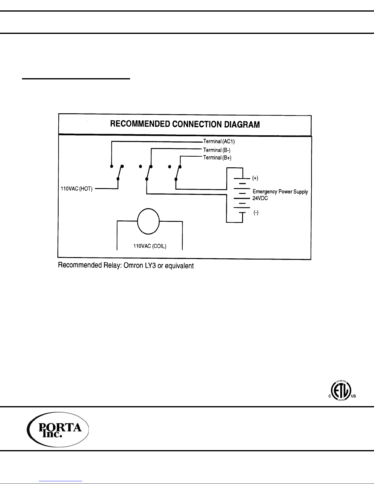
• Emergency Power Input
In the event that the 110VAC power is interrupted, 24VDC may then be applied to operate the unit.
• GAL type G gate switch (optional)
Mounts within the KIS100 chassis
• Micro-switch slow downs and limits
Provide a simple and accurate means of decelerating and stopping the gate
• Magnetic coupling of gate to operator
Provides a simple and positive means of preventing damage or injury in the case of an
obstruction. If the resistance to gate closure exceeds the magnetic coupler, the gate dis-engages
and becomes a manual gate. There is nothing to get out of adjustment or reset. This coupling
system also allows for moderate mis-alignment of operator and gate.
•14" gate arm
Reduces bottom hinge lag
• Quiet Operation
A precision ground lead screw drive system provides virtually silent operation.
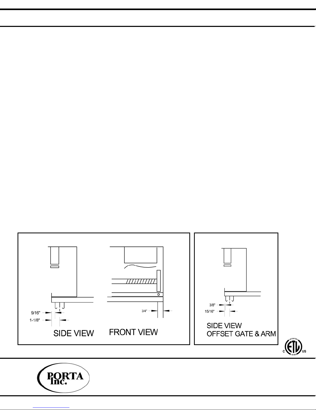
• Retrofit existing installations
The footprint of the KIS100 is the same as the standard Accordion gate
• PWM motor drive
Provides quiet operation, longer motor life and reduced power consumption.
ATTENTION!
WARNING: The installation of this device should only be performed by a professional elevator
technician that has a full understanding of this device’s operation and function.
Note: If there is any doubt regarding the installation procedures, please call the factory for
assistance. We are available M-F 8:00 am to 5:00 pm Central Time.
WARNING: Failure to comply with all instructions and “WARNING”(s) can result in
a safety system compromise. This, in turn, can result in serious injury or death.
Porta Inc. Phone: (847) 593-4900
2420 Hamilton Rd. Fax: (847) 593-1394
Arlington Heights, IL 60005 website:emiporta.com
PATENT PENDING

KIS1OO-Accordion Gate Operator Page 2
Technical Specifications
Input Power 120VAC
Motor 90VDC
Motor Drive 1A(P.W.M.)
High Speed (nom.) 107sec.
High Speed Adj. 0-120%
Low Speed Adj. 0-80%
Drive Belt 0-Ring (343)
Dry Contact
120VAC
Control Interface
Options
12/24 VDC
Gate Switch GAL type G
Gate Travel "L"
29 Inches 36 1/2"
32 Inches 39 1/2"
36 Inches 43 1/2"
42 Inches 49 1/2"
Porta Inc. Phone: (847) 593-4900
2420 Hamilton Rd. Fax: (847) 593-1394
Arlington Heights, IL 60005 website:emiporta.com
PATENT PENDING

KIS100 Power Gate Operator
INSTALLATION - MECHANICAL
1. Unpack the unit, remove the cover, and check for any physical damage before proceeding.
2. Check to see that you have the correct hand unit. The operator is designed so the motor is on the
stack side of the gate. The operator can be made to work on the opposite hand, but on most jobs it
will require a large amount of overhang. The chassis is symmetrical; if necessary you can covert hand
in the field, however this will VOID THE WARRANTY.
3. Operate the gate manually. The door must operate smoothly without any binding. Correct any
problems with the gate before proceeding.
4. Mark a line on the car top corresponding to the centerline or the front edge of the gate track.
5. If the distance from the gate track centerline to the edge of the car top is more than 1 -1/8", there
are two options: Shim out connecting arm (maximum recommended distance is 1/2"), or cut back
the edge of the car top. If you need to cut back the car top, do so now - cut so there is 1-1/8" from
the gate track centerline to the edge.
6. OFFSET GATE APPLICATION
For an offset gate, refer to Figure 1b. If the distance from the gate track centerline to the edge of the
car top is more than 15/16”, cut back the edge of the car top. As illustrated in Figure 1b, the gate track
centerline to the car top edge should not exceed 15/16”.
7. Place the operator on the cartop. Set the operator so the front edge is 1-1/8" (max) from the
centerline or 9/16" (max) from the front edge of the gate track toward the inside of the car, and so the
lead end is 3/4" past the gate strike. See Fig 1.
Page 3
Porta Inc. Phone: (847) 593-4900
2420 Hamilton Rd. Fax: (847) 593-1394
Arlington Heights, IL 60005 website: emiporta.com
FIG. 1 FIG. 1b

KIS100 Power Gate Operator
INSTALLATION - MECHANICAL (CON'T)
7. Pull the gate to its fully closed position. Check that the drive nut is
about 1/2" away from the closed side pillow block; manually rotate the
lead screw if necessary (it will be easier to rotate with the drive o-ring
removed). Place the gate arm magnet on the magnet flag; the middle of
the magnet should be in the middle of the flag. Check that the gate
switch is closed, but still has about 1/4" of follow-up. See Fig 2.
8. The gate arm should line up with the gate lead post. If not, minor
adjustments can be made by simply moving the gate arm magnet
around on the flag. Large adjustments will require repositioning of the
operator.
9. With the operator and gate arm in position, mark through the
mounting holes for drilling the car top and the gate lead post.
10. Move the operator so you can drill 1/8" pilot holes in the cartop and
1/4" through holes in the gate
lead post. BE CAREFUL NOT TO DRILL THROUGH THE CAR TOP IF
THE HOLES WOULD BE VISIBLE.
11. Attach the operator to cartop. #12 x 3/4 screws are provided for wood
cartops. Attach the gate arm with 1/4" -20 x 1 1/4" carriage bolts and
acorn nuts. See Fig. 3
12. Manually rotate the lead screw to open the gate about 1/2" from its fully
closed position. Adjust the closed limit so that it "clicks" when the gate is
about 1/4" from being fully closed; check by manually rotating lead screw.
13. Adjust the close slow down limit so that it is about 2" center-to-center
from the closed limit.
14. Manually rotate the lead screw to about 1/2" from its fully open
position. Adjust the open limit so that it "clicks" when the gate is about 1/4"
from being fully open; check by manually rotating lead screw.
NOTE: LEAD SCREW ASSEMBLY IS SELF-LUBRICATING.
LUBRICATION IS NOT RECOMMENDED.
NOTE: IF NEEDED, PETROLEUM JELLY CAN BE USED TO
LUBRICATE THE GUIDE RAIL.
Patent Pending
Page 4
Porta Inc. Phone: (847) 593-4900
2420 Hamilton Rd. Fax: (847) 593-1394
Arlington Heights, IL 60005 website: emiporta.com

KIS100 Power Gate Operator
INSTALLATION - ELECTRICAL
1.The KIS100 is field wired including the gate switch if so equipped. Run field wires from operator through
conduit or greenfield. 2-1/2" knockouts are provided in the chassis for an appropriate fitting.
2. Ground the chassis per code.
3. Verify 120VAC power before connecting the operator.
4. Verify the type and voltage of control signal being used, refer to the Field Connection Diagrams.
5. There are 5 jumpers on the board:
SP1: Auto close; with this jumper installed the operator will automatically close when there is no
signal to open. Remove if controller provides an independent close signal, or for testing and
adjusting.
SP2-SP5: Are used to select the control signalization. Refer to the Field Connections
Diagrams below for the various configurations.
6. To test unit, set speed pots in the middle of their range. Then use on board toggle switch to open and
close the operator. Adjust the speed control and limit switches as necessary.
7. Connect wiring from elevator controller to interface board. Reinstall SP1 if using only an open signal
from the controller.
8. Test the unit for automatic operation and replace cover.
Page 5
Porta Inc. Phone: (847) 593-4900
2420 Hamilton Rd. Fax: (847) 593-1394
Arlington Heights, IL website: emiporta.com
Page6
Patent Pending

Page 6
KIS100 Power Gate Operator
Electrical Schematic
•AUTO CLOSE: Installing jumper SP1 enables this feature.
• Terminals "B+" and "B-" are the 24VDC Emergency Power Inputs.
Do not operate at any higher voltage.
WARNING: 11OVAC Line voltage and 24VDC Emergency Power must not be present at the same
time. If they are, BOARD DAMAGE WILL OCCUR.
• Jumpers SP2 thru SP5 are used to select the control signalization.
• Factory jumper setup is for Dry Contact signalization and Auto Close enabled.
Porta Inc. Phone: (847) 593-4900
2420 Hamilton Rd. Fax: (847) 593-1394
Arlington Heights, IL 60005 website: emiporta.com
Patent Pending

KIS100 Power Gate Operator
TROUBLESHOOTING
Problem Possible Cause Corrective Action
No power Verify 120VAC between "AC1" & "AC2"
Fuse Check Fuse "F1"
Controller Signal Check operation with test switch
No Function
Faulty Limit Verify that limits are closed
wh
e
n n
ot
actuated
No High Speed
Faulty Slow down
Verify that slow downs are
open when not actuated
Slow down not
actuat
in
g
Verify that the cam engages
t
h
e
s
l
o
w
do
wn
No low speed
Faulty Slow down
Verify that slow downs have
continuity when actuated
Loose Pulleys
Verify that the drive and driven
pulley's are tight on their shafts
0-Ring Check for loose or missing o-ring
Motor turns but
no gate movement
Gate Check gate for excessive bind
Check operation with test switchReverse operation
Board wiring or
controller wiring
DOWN is open.
Swap M+ & M- if necessary
Excessive
breakaway force
Step 1
Step 2
Put small washers on the magnets
opposite the flag. If force is still
excessive, go to step 2
Remove a magnet. If force is still
excessive, put small washers on the
remaining magnet opposite the flag.
Board is powered but
motor does not engage Unit has stalled out Step 1: Shut off power supply to unit.
Step 2: Identify and remove the cause of the stall.
Step 3: Power unit back up.
ATTENTION!
If the resistance to gate closure exceeds the magnetic coupler, the gate dis-engages from the operator
and becomes a MANUAL GATE. Advise the user that they must do one of the following:
• Close the door manually to run the elevator
• Cycle the door to re-engage the magnetic coupler.
Porta Inc. Phone: (847) 593-4900
2420 Hamilton Rd.. Fax: (847) 593-1394
Arlington Height, IL 60010 website: emiporta.com
PATENT PENDING
Page 7

Porta Inc. Phone: (847) 593-4900
2420 Hamilton Rd. Fax: (847) 593-1394
Arlington Heights, IL 60005 website: emiporta.com
KIS100 Power Gate Operator
Emergency Power Connections
General information:
The KIS100 has the ability to operate at 24VDC in the event 110VAC power is
lost. The unit will operate at a reduced speed when powered by 24VDC.
Terminals B+ and B- are the battery inputs.
NOTE: It is vital that B+ and B- are not connected to the battery when 110VAC is present on the board.
PATENT PENDING
Page 8
Table of contents