POSIFLEX RT-2015 User manual

1
Package Contents
RT-2015 15” fanless touch terminal or
RT-2016 15.6” fanless touch terminal or
RT-2115 15” fanless touch terminal or
RT-2116 15.6” fanless touch terminal (x 1)
Power adapter (x 1)
Power cord (x 1)
User manual (x 1)
16950900020 Ver. B0
http://www.posiflex.com
RT-2015/2016/2115/2116
Fanless Touch POS Terminal
User Manual

2
SOME IMPORTANT NOTES
FCC NOTES
This system meets industry & government requirements and applicable
standards. This equipment generates, uses, and can radiate radio frequency
energy and, if not installed and used in accordance with the instructions
manual, may cause interference to radio communications. It has been tested
and found to comply with limits for a Class A digital device pursuant to
subpart B of Part 15 of FCC Rules, which are designed to provide reasonable
protection against interference when operated in a commercial environment.
Operation of this equipment in a residential area is likely to cause interference
in which case the user at his own expense will be required to take whatever
measures to correct the interference.
This device complies with part 15 of the FCC Rules. Operation is subject to
the following two conditions: (1) This device may not cause harmful
interference, and (2) this device must accept any interference received,
including interference that may cause undesired operation.
CE CLASS A WARNING
This equipment is compliant with Class A of CISPR 32. In a residential
environment this equipment may cause radio interference.
AVERTISSEMENT CE CLASSE A
Cet équipement est conforme à la classe A de CISPR 32. Dans un
environnement résidentiel, cet équipement peut provoquer des interférences
radio.
WARRANTY LIMITS
Warranty will terminate automatically when the machine is opened by any
person other than the authorized technicians. The user should consult his/her
dealer for the problem happening. Warranty voids if the user does not follow
the instructions in application of this merchandise. The manufacturer is by no
means responsible for any damage or hazard caused by improper application.
LIMITES DE GARANTIE
La garantie prend fin automatiquement lorsque la machine est ouverte par une
personne autre que les techniciens autorisés. L'utilisateur doit consulter son
revendeur pour le problème qui se produit. La garantie s'annule si l'utilisateur
ne suit pas les instructions d'application de cette marchandise. Le fabricant
n'est en aucun cas responsable de tout dommage ou danger causé par une
mauvaise application.

3
警告使用者
這是甲類的資訊產品,在居住的環境中使用時,可能會造成射頻干擾,
在這種情況下,使用者會被要求採取某些適當的對策。
BATTERY CAUTION NOTES
Dispose of used batteries according to the instructions.
Replacement of a battery with an incorrect type that can defeat a
safeguard (for example, in the case of some lithium battery types)
Disposal of a battery into fire or a hot oven, or mechanically crushing
or cutting of a battery that can result in an explosion.
Leaving a battery in an extremely high temperature surrounding
environment that can result in an explosion or the leakage of flammable
liquid or gas.
A battery subjected to extremely low air pressure that may result in an
explosion or the leakage of flammable liquid or gas.
BATTERIE ATTENTION NOTES
Jetez les piles usagées conformément aux instructions.
Remplacement d'une batterie avec un type incorrect qui peut annuler
une sauvegarde (par exemple, dans le cas de certains types de batterie
au lithium)
Mise au rebut d'une batterie dans le feu ou dans un four chaud, ou
écrasement ou coupure mécanique d'une batterie pouvant entraîner une
explosion.
Laisser une batterie dans un environnement environnant à des
températures extrêmement élevées pouvant entraîner une explosion ou
la fuite de liquide ou de gaz inflammable.
Une batterie soumise à une pression atmosphérique extrêmement basse
pouvant provoquer une explosion ou une fuite de liquide ou de gaz
inflammable.
警告
本電池如果更換不正確會有爆炸的危險,請依製造商說明書處理用過之
電池。

4
Views of RT-2015/2016/2115/2116
Front View
15” RT-2015/2115
15.6” RT-2016/2116
Rear View
Bottom View
RT-2015/2016/2115/2116
P-Cap Touch Panel
LED indicator
LED indicator
Base Stand
Camera (Optional)
System Back Cover
Stand Cover
Cable Exit
Attachment Bay
Release Lever for System Back Cover
Screw for Fire-Resistant
System Back Cover

5
Left-Side View
Views of RB-5000 UPS Base Stand (Option for RT Series Model)
Top View Bottom View
When the AC power is turned off, the RT terminal will begin to be
powered by the UPS battery and the RB-5000 will beep once every
three seconds. At this time, back up the data on the terminal
immediately and power off the RT terminal.
When the AC power is turned off, if the UPS battery is very low, the
RB-5000 will beep once every second. At this moment, power off the
RT terminal immediately.
To get more detailed information of RB-5000, please contact the service team
of Posiflex or download the RB-5000 user manual from Posiflex Global
Website: (http://www.posiflex.com/en-global/Download/download).
Power Button
Brightness Adjustment Button +
Brightness Adjustment Button -
BATT.
DC OUT
DC IN
Rubber Foot
Battery Cable
Screw Hole
Through Hole

6
View of I/O Interface of RT-2015/2016
View of I/O Interface of RT-2115/2116
Positioning your POS for a Perfect Viewing Angle
Steady the base with one hand, and then tilt the screen
in the direction shown by the arrow in the figure.
Please do NOT press on the LCD panel while
setting up the tilt angle.
Installing Power Adapter and Cables
The following provides instructions required to install your cables.
USB 3.0 Port
DB9 COM Port
CR Port
LAN Port
DC IN
Power
Connector
Mini DisplayPort
RJ50 COM Ports
USB 3.0 Ports
DB9 COM Port
CR Port
LAN Port
DC IN
Power
Connector
Mini DisplayPort
RJ50 COM Ports
USB 2.0 Ports
USB 2.0 Ports

7
1. Lay the terminal with its rear facing
towards you and tilt the screen all the way
down.
2. Remove the system back cover.
2.1 If the system back cover is fire-resistant, first locate the screw as
indicated in the figure, and then remove it.
2.2 Hold down the release lever at the bottom of
the system back cover and then pulling the
cover outwards.
3. To remove the stand cover from the base, grab the top side of the
cover, (1) lift the stand cover up gently, (2) pull it at a 45 degree
angle, and then (3) slide it in the horizontal direction shown by the
arrow.
1
2
3
Screw for Fire-Resistant
System Back Cover

8
4. Connect the connector of the power adapter
to the DC-IN power jack. If necessary,
properly insert other cables into the correct
port.
5. Neatly arrange the cables. Locate the cable holder inside the base as
shown in the figure. Push down the lever to release if from the hook,
pass the cable through cable holder, and then press down the lever
again to lock it onto the hook.
6. Make sure the cord can be held into place and
passed through the cable exit after sliding back
the stand cover.
7.
7.1 Place back the sytem back cover. Make sure
it is well locked into place with a click sound.
7.2 For the fire-resistant system back cover, please insert another
screw into the screw hole indicated in the figure, and secure it.
Cable holder
Screw for Fire-Resistant
System Back Cover

9
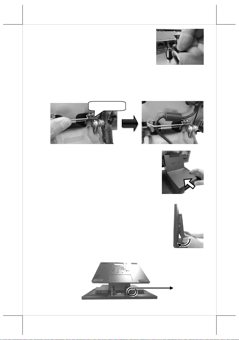
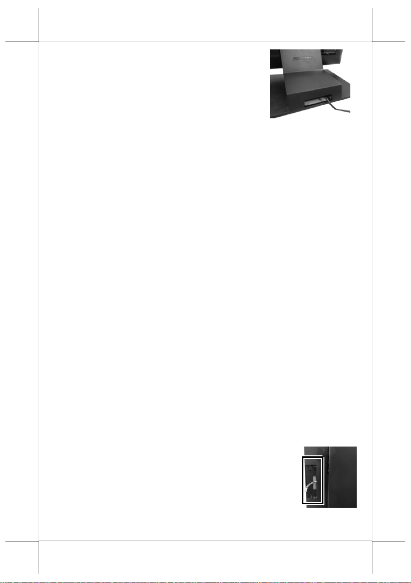
8. Make sure the cable could be pulled out of the
cable exit from the bottom of the base.
Cable connectors like the connector of LAN cable have to be gently inserted
until a click sound is given. It is recommended that the I/O ports, such as COM
(DB9) port, should be fastened with connector thumb screws after the I/O
cable connectors are completely connected. And please make sure that each
connector has to be connected to the right peripheral device in the right way.
CAUTION: On doing insertion or extraction of a cable connector, please
always hold the connector head itself instead of pulling the cable wire.
Doing this could damage the cables, which is considered as an artificial
damage and is not covered by the warranty. The means of power cord
should be connected to a socket-outlet with earthing connection.
ATTENTION: Lors de l'insertion ou de l'extraction d'un connecteur de
câble, veuillez toujours tenir la tête du connecteur elle-même au lieu de
tirer le fil du câble. Cela pourrait endommager les câbles, ce qui est
considéré comme un dommage artificiel et n'est pas couvert par la
garantie. Le cordon d'alimentation doit être connecté à une prise de
courant avec mise à la terre.
Installing Optional Upgrade Kits and Peripherals
RT-2015P/2016P/2115P/2116P is an expandable model which allows you to
upgrade its own capacity by additionally installing multiple peripheral devices,
such as magnetic stripe reader (MSR), fingerprint or iButton sensors, and 2nd
rear-mount POS monitor, according to your preference. The following will
give you brief instructions on how to expand on your current POS system with
these optional upgrade kits. Before proceeding with the installation of
peripherals, please make sure the POS system is completely shut down to
prevent damage.
Installing Side Mount Upgrade Kits
Located at left side on the back of your system unit, side
mount compartment is mainly used for installation of side-
mounted equipment, such as magnetic stripe reader. For
detailed installation instructions, please refer to the user
manual specific to the device which you intend to mount
onto the terminal.

10
Installing Rear-Mount POS Monitor
RT-series POS terminal also allows you to additionally
install rear-mount POS monitor to expand its functionality.
Regarding the step-by-step instructions which aim to help
you mount it onto your POS system, Please refer to the
user manual specific to the device you intend to install.
Installing PoweredUSB or USB Hub
Please go through the below steps to complete the installation of
PoweredUSB or USB hub.
1. After tilting the screen all the way down, remove the system back
cover.
1.1 If the system back cover is fire-resistant, first locate the screw as
indicated in the figure, and then remove it.
1.2 Hold down the release lever at the bottom
of the system back cover and then pulling
the cover outwards
2. To remove the stand cover from the base, grab the top side of the
cover, (1) lift the stand cover up gently, (2) pull it at a 45 degree
angle, and then (3) slide it in the horizontal direction shown by the
arrow.
3
2
1
Screw for Fire-Resistant
System Back Cover

11
3. Align the two screw bolts at the bottom of PoweredUSB or USB hub
with rail slots in the base.
4.
Push PoweredUSB or USB hub in the
direction shown by the arrow to lock it
into place.
To remove the PoweredUSB or USB hub from the rail slots, press
down the hubs first and then push it outwards.
5. Install power adaptor extension cable, USB cable, and power adaptor
for PoweredUSB hub.
5.1 Insert one end of the provided power
adaptor extension cable to DC Input port
of PoweredUSB hub and another end to
DC-in power jack of the terminal.
5.2 Insert mini-USB connector of the USB
cable to PoweredUSB hub and another
end to USB3.0 port of the terminal.
5.3 Connect the connector of the power
adapter to DC Output port of
PoweredUSB hub, and the other end to the
electrical outlet.

12
6. To Install USB cable for USB hub, Plug
Type-A connector of USB cable to USB
Port of USB hub and the other end of USB
cable to USB3.0 port of the POS terminal.
7. Neatly arrange your cable and then slide
back the stand cover.
8.
8.1 Place back the system back cover. Make
sure it is well locked into place with a
click sound.
8.2 For the fire-resistant system back cover, please insert another screw
into the screw hole indicated in the figure, and secure it.
Status LED Indicator
LED status indicator, which is located at the bottom edge of the LCD panel, is
mainly responsible for notifying users of the current system status by emitting
various LED signals. In the chart provided below, it describes all the possible
LED status as a quick reference.
15” RT-2015/2115
LED Status
Description
Off
System power OFF
Green
System standby
Blue
System power ON
Screw for Fire-Resistant
System Back Cover

13
15.6” RT-2016/2116
LED Status
Description
Off
System power OFF
Orange
System standby
Blue
System power ON
Powering ON/OFF RT-2015/2016/2115/2116
Power ON RT-2015/2016/2115/2116
Press down the power button to power on the POS.
Power OFF RT-2015/2016/2115/2116
In most cases, press the power button of the POS to
power the system off. If the terminal fails to turn off
the machine for unknown reasons, please be advised
to hold the power button more than 10 seconds to
force a shutdown of the system.
Installing an Operating System
You are highly advised not to install an operating system on RT-
2015/2016/2115/2116 without professional instructions. Improper installation
could lead to system malfunction or failure. Please contact with your dealers
about the issues of operating system installation.
Performing System Recovery
For RT-2015/2016/2115/2116 model with preloaded operating systems,
Recovery DVD which includes useful utilities will be provided in the package
to assist you in efficiently restoring or repairing your damaged system.
However, you are not encouraged to recover your system without the help of
system integrators. Please be advised to contact your service center for further
assistance with system recovery.
Operation Environment
To prevent RT-2015/2016/2115/2116 from overheating, it is suggested to
position your terminal in a well-ventilated working environment. In doing so,
please be advised to keep the POS terminal at least 25mm away from other
devices to ensure the machine is properly cooled down and functioning
normally.
Power
Button

14
Specifications
RT-2015/2016
RT-2015
RT-2016
CPU
Intel Bay Trail-D
Intel Celeron - J1900 (2.0 GHz, Quad-Core, 10W
TDP)
System Memory
DDR3L, SO-DIMM socket x 1, max. 8GB
Storage Device
SATA Storage x 2
OS Support
Windows 7 / POSReady 7 / Windows Embedded
8.1 Industry / Windows 10 IoT
Power Supply
12V / 60W, can be upgraded to 150W while
adopting PoweredUSB module
LCD Panel
15"TFT LCD with
LED backlight
15.6" TFT LCD with
LED backlight
LCD Resolution
1024 x 768
1920 x 1080
Touch Sensor
P-CAP touch
Serial Port
3 ports, DB9 x 1 + RJ-50 x 2
USB Port
4 ports, USB3.0 x 1 + USB2.0 x3
LAN Port
10/100/1000 Mb x 1
Display Port
eDP connector (internal header, support 15"
and 15.6" LCD)
VGA + USB + 12V (internal header,
supporting 2nd monitor 9.7"/10.1"/15")
1 x Mini DP port (on I/O plate)
CR Port
1 port, controlling 2 CR
Audio Port
Internal 2W speaker x 1
Extension Slot
M.2 slot x 1
Dimension
(W x V x D in mm)
Main Unit:
368 x 292 x 46.6
with base stand :
368 x 325 x 207
Main Unit:
402 x 251 x 41.2
with base stand :
402 x 297 x 207
Environmental
Requirements
Operating:0°C 〜40°C, 20%RH - 90%RH
Storage:-20°C 〜70°C, 10%RH - 90%RH
Regulation Rules
FCC/CE
Attachment
RA-101
Slim MSR attachment for RT series
RA-103
iButton (or RFID) with one USB port attachment
for RT series

15
RA-104
2D scanner attachment for RT series
RA-301
3-in-1 MSR + Fingerprint Sensor + 2D scanner
attachment for RT series
LM/TM-4010
9.7" 2nd display for RT series terminal
LM/TM-4011
10.1" 2nd display for RT series terminal
LM/TM-4015
15" 2nd display for RT series terminal
PU-460
PoweredUSB module to support 12Vand 24V
Powered USB ports
RT-560
USB port replicator ( USB2.0 x 4, installed in base
stand)
RB-5000
UPS battery stand
RT-2115/2116
RT-2115
RT-2116
CPU
Intel Apollo Lake SoC
Intel Celeron - N3350 (2.4 GHz, Dual-Core, 6W
TDP)
System Memory
DDR3L, SO-DIMM socket x 1, max. 8GB
Storage Device
SATA Storage x 2
OS Support
Windows 7 / POSReady 7 / Windows Embedded
8.1 Industry / Windows 10 IoT
Power Supply
12V / 60W, can be upgraded to 150W while
adopting PoweredUSB module
LCD Panel
15" TFT LCD with
LED backlight
15.6" TFT LCD with
LED backlight
LCD Resolution
1024 x 768
1920 x 1080
Touch Sensor
P-CAP touch
Serial Port
3 ports, DB9 x 1+ RJ-50 x 2
USB Port
4 ports, USB3.0 x 2 + USB2.0 x 2
LAN Port
10/100/1000 Mb x 1
Display Port
eDP connector (internal header, supporting
15" and 15.6" LCD panel)
VGA + USB + 12V (internal header, support
2nd monitor 9.7"/10.1"/15")
1 x Mini DP port (on I/O plate)
CR Port
1 port, controlling 2 CR
Audio Port
Internal 2W speaker x 1
Extension Slot
M.2 slot x 1

16
Dimension
(W x V x D in mm)
Main Unit:
368 x 292 x 46.6
with base stand :
368 x 325 x 207
Main Unit:
402 x 251 x 41.2
with base stand :
402 x 297 x 207
Environmental
Requirements
Operating:0°C 〜40°C, 20%RH - 90%RH
Storage:-20°C 〜70°C, 10%RH - 90%RH
Regulation Rules
FCC/CE
Attachment
RA-101
Slim MSR attachment for RT series
RA-103
iButton/RFID) with one USB port attachment for
RT series
RA-104
2D scanner attachment for RT series
RA-301
3-in-1 MSR + Fingerprint Sensor + 2D scanner
attachment for RT series
LM/TM-4010
9.7" 2nd display for RT series terminal
LM/TM-4011
10.1" 2nd display for RT series terminal
LM/TM-4015
15" 2nd display for RT series terminal
PU-460
PoweredUSB module to support 12Vand 24V
Powered USB ports
RT-560
USB port replicator ( USB2.0 x 4, installed in base
stand)
RB-5000
UPS battery stand
※
The product information and specifications are subject to change without
prior notice. To get the detailed information on the RT-2015/2016/2115/2116,
please check this model from Posiflex Global Website
This manual suits for next models
4
Table of contents
Popular Postal Equipment manuals by other brands

Postal Pro
Postal Pro Hampton PP300 installation instructions

FP
FP FPi 5600 Unpacking and Installation

Francotyp-Postalia
Francotyp-Postalia FPi 500 user guide

Briefkasten Manufaktur
Briefkasten Manufaktur Designer BIG Charger operating instructions

Neopost
Neopost IJ 70 user guide

quadient
quadient IN-360 Series Quick installation guide